Cerlic ITX 20 User manual

2002-11-19 MANE11/02 Ver 2.00
ITX 20
Suspended Solids
Sensor

-2 -
TABLE OF CONTENTS
1. Introduction............................................................................................................3
2. A few words about this manual........................................................................3
3. Design......................................................................................................................3
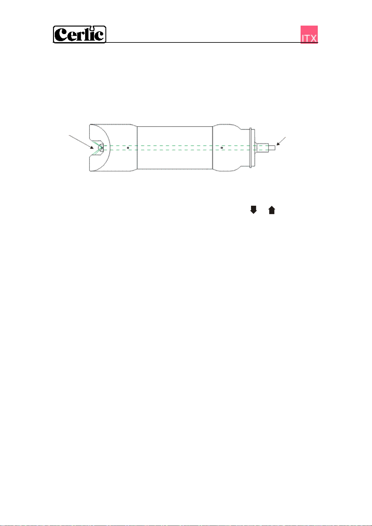
4. Measuring principle..............................................................................................3
5. Unpacking the ITX Suspended Solids Sensor..............................................4
Damages ............................................................................................................ 4
Packaging........................................................................................................... 4
Content............................................................................................................... 4
Optional parts for ITX Suspended Solids Sensor:............................................. 4
6. Mounting of ITX Suspended Solids Sensor...................................................5
Cable Connections ............................................................................................. 5
Installation Tips ................................................................................................. 5
7. Removing the sensor...........................................................................................6
8. Cleaning..................................................................................................................7
Cleaning the Flushing Nozzle............................................................................ 7
Mounting plate for cleaning solenoid valves..................................................... 8
9. Menu for ITX sensor.............................................................................................9
Settings .............................................................................................................. 9
Calibrate............................................................................................................. 9
System.............................................................................................................. 10
10. Calibration ............................................................................................................11
Getting good measurement .............................................................................. 11
Calibration screen............................................................................................ 11
Zero Calibration............................................................................................... 12
Entering sample calibration points –using a sample bucket........................... 13
Alternate calibration, placing sensor in a basin or channel............................. 13
11. Scaling...................................................................................................................14
12. Technical description of sensor ITX 20........................................................15
Optional parts for ITX Suspended Solids Sensor:........................................... 15
13. Dimensions...........................................................................................................16
Appendix 1, Assembly of handrail mounting kit...............................................17
Appendix 2, Assembly of adjustable slide rail...................................................18
Appendix 3, Support information..........................................................................19
Appendix 4, Setup information..............................................................................21

-3 -
1. Introduction
The ITX sensor is designed to measure suspended solids concentrations in liquids.
Combined with the BB2 control box, the sensor is used to measure suspended solids
content as a function of the ability of suspended materials to absorb and reflect NIR-
light (Near Infra-Red).
2. A few words about this manual
This manual details installation procedures and operational features of the Cerlic ITX
sensor. Menu navigation and technical data for the BB2 control box can be found in the
BB2 service manual.
3. Design
The ITX sensor is manufactured with 316SS (SS2343) stainless steel. The inside of the
sensor is designed to achieve the highest self-cleaning effect, providing an exact and
reliable measurement with the least possible maintenance under critical applications.
The measuring lenses within the housing are made of glass. The electronics and optics
are protected in the rugged casing, ensuring its reliability in very demanding
environments.
The sensor has a fixed, shielded 10 m (33’) cable used for signal transmission between
the sensor and the BB2 control box. The cable sheath is made of Hytrel and is highly
resistant to aggressive materials and fluids.
4. Measuring principle
The ITX measures transmitted light through the liquid. The measuring principle is based
on the suspended particles’ ability to absorb and reflect NIR (Near Infra-red) light. The
light source is a light emitting diode that pulses and emits monochromatic light with a
wavelength of 880 nm. The detected measuring signal is inversely logarithmical
proportional to the consistency or suspended solids. Signal treatment or linearization is
done within the BB2 control box.
Cross-section of measuring gap.

-4 -
5. Unpacking the ITX Suspended Solids Sensor
The unit has been tested and approved before delivery from the supplier. Please check
to confirm that no visible damages occurred during shipment.
Damages
If damages occurred during shipment, immediately contact UPS or other truck line as
well as your Cerlic representative. The shipment can be returned only after contact has
been made with Cerlic.
Packaging
The original packaging is designed to protect the equipment and should be used for
storage or if the goods must be returned.
Content
Please check that the content corresponds to your order and packing list.
Every shipment should include:
•ITX Sensor w/ 10 m (33ft) cable and flushing hose, P/N 11305455
Optional parts for ITX Suspended Solids Sensor:
•Mounting bracket X, incl. rod holder P/N 11205539
•Telescopic rod, 4 m, incl. transmitter holder P/N 20205501
•Adjustable slide rail sensor holder P/N 11205600
•Solenoid valve for flushing P/N 11705516
•Aluminum handrail mounting plate predrilled for BB2
and solenoid valves w/ u-bolts, outside US version P/N 10605533
•Aluminum handrail mounting plate predrilled for BB2
or solenoid valves w/ u-bolts, US version P/N 31204049
•33 ft. (10m) extension cable with plug-in connectors. P/N 20805510
•Y-Splitter for two sensors to one BB2 control box P/N 21505534

-5 -
6. Mounting of ITX Suspended Solids Sensor
The ITX is mounted on a telescopic fiberglass rod and placed in a mounting bracket that
fastens to a handrail. Please refer to Appendix 1. As an alternative way of mounting the
sensor, an adjustable slide rail holder is available, please refer to the Appendix 2 for
further details.
When the sensor is measuring in a fume, it is important to find a place where the
suspended solids concentration is representative.
Make sure the flushing nozzle is downstream from the lenses pointing against the
stream. This will avoid having the measurement disturbed by turbulence from the
nozzle. At the same time it will produce a shield around the nozzle, due to a constant
over pressure, preventing particles from getting in.
Cable Connections
Connect the sensor to the BB2 control box using the attached connector on the end of
the sensor cable. In the event that two sensors are to be connected to the same BB2
control box, use the Y-splitter.
NOTE! Never try to turn the connector housing to fasten or remove the connector, only
the fluted ring at the top of the connector shall be turned.
Installation Tips
•Adjust the rod so that the sensor is at least 12” below the liquid surface or the lowest
water level in decant applications to prevent the sensor from coming out of the
liquid.
•In an aeration tank, ensure that the sensor is not directly above a diffuser head. It
should be on the backside of the rolling diffuser effect.
•Flushing may not be required if the tank is well agitated. To verify the need for
flushing, remove the sensor from the liquid after it has been in the liquid for several
days. Place the sensor in a bucket of clean water and note the concentration value.
If the value does not get close to zero, then the flush system should be utilized.
•When installing in a clarifier, compressed air flushing is required due to no agitation
of liquid and to remove oil and grease film on lens. This is especially applicable in
primary clarifiers.
•When using the ITX for influent applications, always install the unit after the bar
screen. If the bar screen spacing is larger than ¼’ (6 mm), then a baffle or diffuser
plate should be installed in front of sensor to prevent rags from catching on the
sensor head. On influent applications, compressed air flushing is recommended due
to the oil or grease in the liquid.
•In effluent applications a CTX type of sensor is recommended, it has better
resolution at low concentrations.

-6 -
7. Removing the sensor
The sensor is removed in the following steps:
•Disconnect the sensor cable from the BB2 and the flushing hose from solenoid.
•Open the clamp, and pull the rod out of the mounting bracket
•Make sure all water inside the rod is drained.
•Clean the sensor and rod with a brush or clean cloth. Do not use a wire brush!
•Open the black sensor adapter.
•Flush the inside of the rod with clean water.
•Mount the protective cap (or a small plastic bag) on the sensor cable connector.
•Pull the cable and flushing hose out of the rod.
•Blow compressed air through the flushing hose to get rid of the water in the hose
and the sensor.

-7 -
8. Cleaning
The sensor is equipped with built-in flushing nozzles. The nozzles are used to direct the
cleaning liquid or air through a ¼” hose that is connected to the top of the sensor
housing. A solenoid valve that is wired to an alarm relay in the BB2 control box
controls the air or liquid. Water is recommended for flushing in aeration basins.
Compressed air is recommended for most other applications.
Flushing tubeWater
Flushing must be activated in the “Settings” menu in the BB2 control box:
•Select the ITX transmitter in the Main Menu by using the or buttons.
•Press ENTER for approximately five seconds to enter the Transmitter Menu.
•Use the arrows to select “Settings” and press ENTER.
•Use the arrows to select “Cleaning” and press ENTER.
•In the “Cleaning” submenu, adjust the “Cleaner” setting to “flush” and specify
the cleaning interval in minutes and the flush time in seconds.
•Specify the relay to be used according to the wiring inside the control box. For
example, if the solenoid is wired to relay #1, select “#1” for flushing.
•“Next time” displays the next time flush will be activated, pushing ENTER will
set it to current time and those start cleaning..
NOTE! Pay attention to the requirements for protection against backflow, according to
the EN 1717 standard for drinking water devices. If possible, use plant reuse water or
effluent water for cleaning.
Cleaning the Flushing Nozzle
The flushing nozzle and sensor cannot be disassembled in the field. An attempt to
disassemble will void the warranty. If the flushing nozzle becomes plugged, it can
usually be cleaned by backflushing it with clean water. Before attempting to backflush,
close the valve for the flush water source and disconnect the sensors flushing hose from
the solenoid valve. Then, place a ½” hose over the flush nozzle and carefully open the
water valve. The pressure should clear the line of solids. If backflushing does not work
initially, try cleaning the three flushing nozzles with a needle. Try backflushing the
nozzles again as described above until clean water comes out at the solenoid valve end
of the hose.

-8 -
Mounting plate for cleaning solenoid valves
To provide an easy mounting of solenoid valves for the built-in flushing nozzles Cerlic
offers a predrilled Aluminum handrail mounting plate. The Mounting plate is fixed to
the rail using two u-bolts.
Please see technical specifications for details and ordering information on Solenoid
Valves and Mounting Plate.
Mounting plate for one or two solenoids,
outside US version.

-9 -
9. Menu for ITX sensor
Use or to select the sensor in the main display. The menu for the selected sensor
is accessed by pressing ENTER for five seconds. If the selected sensor is not active (the
text No transmitteris shown) a warning is displayed that asks you to make another
choice in order to show the sensor menu.
Settings
I-Time Integration time or dampening -can be set up to 999 seconds
Unit ”%”, ”ppm”, ”g/l”, or ”mg/l”
Alarm Relay ”-” ”#1”, ”#2”, or ”#1 and #2”. Check that the relay is not being
used for cleaning
Analog ”None”, ”Channel 1”, ”Channel 2”, or ”Both”. Pick which analog
output contacts are to be used with sensor
Cleaning Press ENTER to go to Cleaning program
Cleaner ”None”, ”Flush”, or ”Brush”. Do not select “Brush” since this
does not exist for ITX sensor
Interval min 0-999 minutes, time between cleaning cycles
Length sec 0-999 seconds, duration of flushing cycle
Freeze sec 0-999 seconds, extra freeze time of output signal after a
flushing cycle
Relay ”-”, ”#1”, or ”#2”. Select relay to operate solenoid for flush cycle.
These are the same relays used for “Alarm relay” above
Next time The next scheduled cleaning time. Pushing “Enter” on this line
will set the time to current time and start a cleaning cycle. This
could be used to test the “Flush” cycle.
Calibrate
Take sample No, Zero, #1, n#2, #3, #4, #5. Sensor stores current MS (light)
value in memory and you enter a lab solids value below to
complete calibration.
Con Current concentration, (same as shown in the main menu)
Sample #1 Lab test –consistency/suspended solids value for Sample 1
Sample #2 Lab test –consistency/suspended solids value for Sample 2
Sample #3 Lab test –consistency/suspended solids value for Sample 3
Sample #4 Lab test –consistency/suspended solids value for Sample 4
Sample #5 Lab test –consistency/suspended solids value for Sample 5

-10 -
Scale
Max 0-99.9 % or 0-99999.9 ppm, mg/l, or g/l (units selected in the
“Settings” menu), equal to 20 mA output signal.
Min 0-99.9 % or 0-99999.9 ppm, mg/l, or g/l (units selected in the
“Settings” menu), equal to 4 mA output signal.
Hi Alarm 0-99.9 % or 0-99999.9 ppm, mg/l, or g/l (units selected in the
“Settings” menu) , the value zero inactivates the alarm
Low Alarm 0-99.9 % or 0-99999.9 ppm, mg/l, or g/l (units selected in the
“Settings” menu) , the value zero inactivates the alarm
System
Type Type of sensor, read only
Serial Serial number of the sensor, read only
SoftW Software version of the sensor, read only
Temp Sensor temperature, read only
Samples Press “ENTER” to go to view SA values and consistency or
suspended solids values. This is a READ ONLYSection.
SA 0 SA value for zero sample
SA 1 SA value for sample # 1
Cons 1 Lab test -consistency or suspended solids value for Sample # 1
…. SA and Cons repeated for samples 2 to 5
Info Press “ENTER” to go to “info” read only menu. This menu is for
Cerlic internal use, it may change without notice
MS linearized light signal, which are SA values in calibration chart
Con Unit value in %, ppm, mg/l, or g/l after MS value has been
converted to units due to sample values. This is displayed on
main screen
SA 0 SA value for zero sample
SA 1 SA value for sample # 1
Cons 1 Lab test -consistency or suspended solids value for Sample # 1
Ch1a Raw value for channel 1
Ch1 Raw value for channel 1, compensated for changed intensity
Zero Int Intensity for clear water, set during zero calibration
Intensity Currently used intensity
I-offset Intensity offset, set during zero calibration
Temp Calib Compensation factor for temperature drift on low solids
applications
Samp/s Number of samples per second
Service Not accessible for users.

-11 -
10. Calibration
The BB2 has a self-optimizing calibration algorithm/curve able to handle several
calibration points in order to give maximum measuring precision in difficult
applications. Usually however, a single point calibration is preferred. After a calibration
has been carried out, make it a habit to look at the calibration curve in the sensor
information screen to make sure it represents a smooth line without ant sharp bends.
Getting good measurement
Statistic adjustment of the lab sample value is a much better way to good measurement
than frequent calibration. This is done comparing the lab results with the instrument
reading over time. If a systematic discrepancy is detected, the value of the lab sample
used in BB2 is changed accordingly. If for example several lab results for a period of
time in average shows 5% more than the instrument, the sample value in BB2 shall be
increased 5% of its value, e.g. if the sample value is 10000 mg/l it shall be changed to
10500. Using statistic method will increase the accuracy and reliability of the
measurement as time passes while new calibrations will start from scratch.
Calibration screen
The ITX sensor information menu is the calibration curve screen. To change between
the main menu and the calibration screen, press and ENTER simultaneously.
BB2 uses at least a zero sample and one sample (two point’s calibration). Up to five
samples may be used to create a calibration curve (multi point calibration). The samples
are sorted internally in order of signal intensity. The sample numbers however, doesn’t
change, only the order they are used. The calibration menu displays sample values
placed in a graph.
•X-scale displays consistency/suspended solids, where min–value (4 mA output) is
shown to the left and max -value (20 mA output) is shown to the right.
•Y-scale displays the light loss due to solids from the sensor light source. BB2 uses
the light loss values to calculate which measuring signal corresponds to min-
consistency/suspended solids and max-consistency/suspended solids.
•Actual measuring value is indicated with an arrow that moves up and down to the left
of the Y-scale axis.
•Samples that are not within the chosen scale of the active sensor are not displayed on
the calibration screen. However, these samples are still used in the calculations. If
Two points calibration Several points calibration
C

-12 -
you want to see a point outside the sensor scale, then you may temporarily change
the scale under SETTINGS in the sensor menu.
If the sample values are switched or the lab result is incorrectly performed, then the
calibration curve will be incorrect. Such a mistake is easy to discover on the calibration
screen since a part of the calibration curve will go in the wrong direction. Different
measuring values should never correspond to the same consistency / suspended solids.
Incorrect calibration!
Zero Calibration
The sensor is zero calibrated at the factory, and does not often need to be zero calibrated.
Before doing a zero calibration, always check that it is really needed. Make sure the
lenses are clean, and use clean de-aerated water to check the meter reading. Tap water is
best de-aerated by leaving the water in an open bucket for at least two hours
Running a zero calibration:
It is important that the instrument has been turned on for about 30 minutes prior to
calibration so that the sensor and electronics can stabilize. Please check that the correct
unit (consistency/suspended solids) is selected for the application. Select unit in the
sensor menu “SETTINGS” –“UNIT”.
•Remove the sensor from the process, clean the sensor head, and dip it in a bucket
of clean water. Even though the sensors have daylight-filters they are sensitive to
the infrared parts of the sunlight. Always cover the sensor and the bucket before
calibration.
•Select the sensor to be calibrated in the menu by using or arrows
•Press ENTER for approximately five seconds to enter the sensor menu.
•Use and arrows to select “Calibrate” and select “Take sample”. Press
ENTER.
•Select “Zero” and press ENTER.
•To acknowledge that you really want to change the zero calibration, select “Yes”
and then press ENTER.
•BB2 will ask you to put the sensor in clean water. Submerge the sensor into the
clean water and cover it from direct sunlight, then press ENTER.
•Wait for the zero calibration to finish. It will take approximately ten to twenty
seconds before the unit returns to the menu.
Detailed procedures for navigating the BB2 software can be found in the BB2 service
manual.
The curve goes backwards
because two samples have been
exchanged when entering the lab
results. Higher Y-value must
mean higher X-value. The curve
must have a direction upwards
and to the right.

-13 -
Entering sample calibration points –using a sample bucket
Fill a bucket with a sample of the liquid you intend to measure. Submerge the sensor
into the liquid. Even though the sensors have daylight-filters they are sensitive to the
infrared parts of the sunlight. Always cover the sensor and the bucket before calibration.
Select the sensor to be calibrated in the menu by using or arrows
•Press ENTER for approximately five seconds to enter the sensor menu.
•Use and arrows to select “Calibrate” and select “Take sample”. Press
ENTER.
•Select “#1”and press ENTER.
•Use the sensor to stir the sample in the bucket until the calibration is finished so
the solids do not settle during calibration. It will take between ten and twenty
seconds.
•Replace the rod/sensor in the SS mounting bracket so the sensor is at least 12”
(36 cm) below the lowest liquid level in the basin. Take the bucket to the lab for
analysis. Note the concentration of the sample determined at the lab.
•Enter sample #1 concentration by going to Sample #1 in the calibration menu
and pressing ENTER. Use the arrows to change the values and ENTER to go to
the next digit.
•When all digits have been entered, you have completed a calibration point.
•Continue the above process to enter additional sample points when desired or
required. Do not enter samples that are identical in concentration or less than
10% from initial values.
Alternate calibration, placing sensor in a basin or channel
•Calibration can be done without the use of a bucket. Make sure that the sensor
is at least 30 cm (12’) below the lowest liquid level. While the ITX is calibrating,
grab a sample of the liquid with a dip bucket to take to the lab for analysis.
Make sure to grab a sufficiently large sample volume for low solids applications.

-14 -
11. Scaling
The “SCALE” menu (see the BB2 manual) allows the user to set the high and low
boundaries for a 4-20mA output signal. In addition, this menu allows the user to set
high and low alarms values that can be used to notify when solids have reached critical
points.
MAX sets the 20 mA point output
MIN sets the 4 mA point output (may be a negative value for special
applications)
H-ALARM sets the High Alarm set point, the value zero inactivates the alarm
L-ALARM sets the Low Alarm set point, the value zero inactivates the alarm

-15 -
12. Technical description of sensor ITX 20
ITX 20 P/N 11305455
Material 316SS (SIS2343)
Dimensions See section 13.
Weight 3.5 lbs. (1,6 kg)
Process connection Submerged
Max Depth 33 ft. (10 m)
Max temperature 140°F (60°C)
Measuring principle Straight transmission, 20 mm measuring line
Light source GaAs diode, 880 nm monochromatic
Cable, connection 5-pin M12-plug
Cable, length 33 ft. (10 m)
Cable, material Hytrel
Flushing, Pressure 60-90 psi (4-6 bar)
Flushing hose, length 33 ft. (10 m)
Flushing hose, material PVC
Enclosure IP68 NEMA 4X
Certificate of conformity
The Sensor has been developed and manufactured in accordance with the following
standards:
SS-EN50 082-2 (immunity), SS-EN50 081-2 (emission), SS-EN61 010-1 (safety)
89/336/EEC, 92/31/EEC, 93/36/EEC, 73/23/EEC
Optional parts for ITX Suspended Solids Sensor:
•Mounting bracket X, including rod holder P/N 11205539
•Telescopic rod, 4 m, including transmitter holder P/N 20205501
•Adjustable slide rail sensor holder P/N 11205600
•Solenoid valve for flushing P/N 11705516
•Aluminum handrail mounting plate predrilled for BB2
or solenoid valves w/ u-bolts, outside US version P/N 10605533
•Aluminum handrail mounting plate predrilled for BB2
or solenoid valves w/ u-bolts, US version P/N 31204049
•33 ft. (10m) extension cable with plug-in connectors. P/N 20805510
•Y-Splitter for two sensors to one BB2 control box P/N 21505534

-16 -
13. Dimensions
2.60” /
8.94” /
10.04” /
2.60”
/ 66

-17 -
Appendix 1, Assembly of handrail mounting kit
•Disassemble the bracket guide and place
around the telescopic rod.
•Use the SS screws on bracket to tighten the
bracket to the rod.
•Mount the Flexible Mounting Bracket on existing handrail or on
separate holder. The bent lip on the mounting plate shall be on top
and faced toward the liquid or tank. A
djust the Mounting Bracket to
the correct angle and tighten the nuts. The bracket shall be fixed to
the rail, and must not be able to rotate around it.
•Insert the PVC bracket guide with the telescopic rod
into the mounting bracket. Make sure that the bracket
guide tracks are properly seated in the bracket.
•Fasten the safety-locking clamp.
•Check that the bracket is safely fixed to the rail for the
spring to work the way it is intended.
Example of a holder
to be used for the
mounting bracket
when no handrail is
•Pull the cable and hose through the sensor holder and rod.
•Connect the telescoping fiberglass rod to the sensor with the two piece black PVC adapter.
•The adapter halves should be tightened until snug, which will leave about 1/16" gap.
NOTE!The gap is required so the water can drain from the rod.
•Adjust the length of the telescopic sensor rod as necessary by twisting the nuts while holding the
rod.
NOTE! Do not extend the rod sections beyond the black lines. This could lead to rod damage.

-18 -
Appendix 2, Assembly of adjustable slide rail

-19 -
Appendix 3, Support information
Before calling Cerlic Support, please collect the information in this form and have it at
hand.
Company _____________________________________________________
Name _____________________________________________________
Phone _____________________________________________________
E-mail _____________________________________________________
Sensor Type _____________________________________________________
Position / Tag _____________________________________________________
First go to the BB2 menu, it is accessed by pressing and ENTER at the same time for
five seconds. Select “System” and press ENTER, then select “Status” and press ENTER
again.
Version _____________________________________________________
Serial _____________________________________________________
Box temp _____________________________________________________
Leave the BB2 menu by pressing and ENTER at the same time. Use or to
select the sensor in the main display. Go to the sensor menu, it is accessed by pressing
ENTER for five seconds. Select “System” and press ENTER.
Type _____________________________________________________
Serial _____________________________________________________
SoftW _____________________________________________________
Temp _____________________________________________________
Select “Samples”, then press “ENTER” to go to the “Samples” sub menu.
SA 0 _____________________________________________________
SA 1 _____________________________________________________
Cons 1 _____________________________________________________
SA 2 _____________________________________________________
Cons 2 _____________________________________________________
SA 3 _____________________________________________________
Cons 3 _____________________________________________________
SA 4 _____________________________________________________
Cons 4 _____________________________________________________
SA 5 _____________________________________________________
Cons 5_____________________________________________________

-20 -
Return to the “System” menu. Select “Info”, then press “ENTER” to go to the “info”
menu.
MS _____________________________________________________
Con _____________________________________________________
SA0 _____________________________________________________
SA1 _____________________________________________________
Cons 1 _____________________________________________________
Ch1a _____________________________________________________
Ch1 _____________________________________________________
Zero Int _____________________________________________________
Intensity _____________________________________________________
I-offset _____________________________________________________
Leave the BB2 menuby pressing and ENTER at the same time.
Table of contents
Other Cerlic Accessories manuals