Cermetek CH2124 User manual

HIGH SPEED INTERNET MODEM FAMILY
CH2124 - Send/Retrieve Email. 2 I/O Ports 2400bps.
CH2160 - Send/Retrieve Email. 2 I/O Ports, V.90.
2005 Cermetek Microelectronics, Inc. Page 1 Document No. 607-0017 Revision I1 (05/05)
FEATURES
•Replaces conventional modems using the world
wide web for communication.
•Transparent internet operations of Point-to-Point
Protocol (PPP), Password Authentication Protocol
(PAP) and Challenge Authentication Protocol
(CHAP) to connect to the Internet.
•Built-in TCP/IP and SMTP to send emails, TCP/IP
and POP3 to retrieve and/or delete emails.
•On Demand and I/O pin event driven email
transmission and retrieval.
•Send/Retrieve email.
•Retrieve select individual message.
•Programmable using serial interface.
•Remote programming using PSTN.
•Resident modem supports: V.90, V.34bis, V.34,
V.22bis, V.22A/B V.23, V.21, Bell 212A and 103,
(depending on model) and can be used in
conventional modem mode.
•Error correcting: V.42 LAPM, MNP 2-4 and MNP10
(CH2160).
•Automatic baud rate adaptability utilizing speed
sensing, flow control and data buffers.
•Serial interface, V.24 (EIA 232-E), 5 volts.
•NVRAM for stored modem (S-Registers) profiles.
•Cermetek @T®AT-like Commands.
•Built-in DAA with 1500 VAC RMS isolation 2122V
peak surge protection.
•UL 1950 and CSA C22.2 950 (Third Edition) Listed,
reference UL File E104957.
•FCC Part 68 Approved/Industry Canada CS-03 Part
I approvable.
•Pin-for-Pin compatible family.
•+5 Volt operation.
•Small size: 1.35” x 1.97” x 0.55” (nominal).
•Low Cost 2400bps version (CH2124).
•Use with any Non-proprietary commercial or private
ISP.
•Cermetek’s iModem Network ISP has 1000s of
local access numbers world wide.
•Failsafe back up 1-800 access number, auxiliary
and alternative telephone numbers available.
•1 year free trial subscription to iModem Network
ISP provided with each iModem.
•iNetWizard®Windows based programming aid
available free-of-change.
INTRODUCTION
Direct machine-to-machine interaction represents the
next logical extension of the internet. Cermetek internet
modem (iModem) products are designed to exploit the
internet to facilitate the utilization of machine-to-
machine interactions. Using email, information can
easily be transferred between systems and can be
transmitted/retrieved at will. Internet email provides low
cost, near real time multi-path communication.
Replacing conventional modems and long distance
telephone lines with local access internet connections
reduces fixed asset and maintenance costs, limits
communication expenses and saves money.
USER FRIENDLY INTERFACE LAYER
All Cermetek iModem products contain a user friendly
interface layer that provides the user transparent
access to the internet. This interface layer, consisting
of various @T®macro commands, has the look and feel
of conventional modem AT commands. With the @T®
macro commands the user can direct the iModem to
compose, edit/modify, send, retrieve and delete email
messages. Internet and email activity status is reported
via the iModem’s V.24 (EIA 232-E) serial interface.
The CH2124/60 products are the first generation
internet enabled devices. These products excel at
sending and retrieving modest amounts of data. Email
messages of approximately 125 ASCII characters in
length can be stored in internal Flash ROM for later
transmission. Emails of larger length can be retrieved.
The CH2124/60 products are ideal for very low cost
controller applications and in applications where limited
data transfer is required.
OVERVIEW OF THE CH21XX iMODEM
A conceptual representation of the iModem in an
embedded environment is presented in Figure 1. As
can be seen in this figure, the iModem requires the
input of various internet parameters to function properly:
user name, user ID, user password, ISP telephone
number, ISP mail server address/name, local email
address/name, destination email address and user
specified email message/input port status.

Cermetek Microelectronics, Inc. High Speed Internet Modem Family
2005 Cermetek Microelectronics, Inc. Page 2 Document No. 607-0017 Revision I1 (05/05)
Figure 1. Conceptualized Block Diagram illustrating the Cermetek CH21XX iModem product family
performing the embedded internet application function.
Cermetek’s iModem products provide the user with the
ability to assign a unique unit name to each iModem
thereby creating a customized identity for each system
containing an iModem product.
Each iModem device stores the user-supplied
parameters in internal memory. These parameters are
retained when power is removed. The user supplied
parameters are loaded into the iModem via the
iModem’s serial interface port utilizing either
Cermetek’s iNetWizard®telecommunications software
package or, alternatively, one of a variety of
commercially available terminal emulation software
packages. iNetWizard®is available free of charge and
runs on any standard PC operating Microsoft Windows.
Internet Connectivity. The CH21XX iModem uses the
user supplied parameters to establish an internet
connection and then send, retrieve and/or delete email.
After completion of the required internet activities, the
iModem terminates the internet connection.
Send, Retrieve and Delete Email. The CH2124/60
products send and retrieve email of modest length. The
pre-stored message length is approximately 125 ASCII
characters. Messages are stored in Flash ROM.
Streaming email is not supported in the CH2124/60
iModem products.
Refer to Cermetek Application Note # 155, @T®
Command Set Description and Usage For CH2124/60
iModems, for more details.
iModem Hardware Configuration. Each CH2160
(CH2124) iModem contains a fully functional 56kbps
(2400bps) modem and the hardware and firmware
needed to provide the internet capability. Because of
the unique architecture of Cermetek iModems, these
iModems have the ability to operate as either an
internet email transceiver or as a high reliability analog
modem. Additionally, the CH2124/60 products support
user remote access which can be used to reprogram or
reconfigure an iModem deployed in the field.
The iModem Family of products are pin compatible with
the CH179X and CH2056 modem products. Referring
to Figure 2, the CH21XX iModem Family consists of an
industrial grade high speed modem module and a µP
controller with associated internal logic. The µP
controller and the logic provide all the functions
required for internet communication via standard PSTN
telephones lines. All CH21XX iModem products utilize
TCP/IP, PPP, PAP, CHAP, SMTP and POP3 internet
protocols.
Remote Access.
Required External Connections. The iModem
requires an external RJ-11C jack for the PSTN line
connection. An ITU-T V.24 serial interface is required
when host processor control of the iModem is required
in the specific application. All retrieved emails are
presented to the host system for further processing
and/or retention via the serial interface.
Approvals. The CH21XX iModem Family is FCC Part
68 approved, UL 1950 and CSA C22.2 950 (Third
Edition) listed and Industry Canada CS-03 Part I
registered.
Physical Dimensions. The modules are designed for
PCB through-hole mounting and are 1.35” x 1.97” x
0.55” in size.
•User Name
•Password
•ISP Telephone Number
•Mail Server Address/Name
•Local Email Address
•Destination Email Address
•User Specified Email
Message/Input Port Status
•User ID
User Supplied Parameters
•
Send email
•Retrieve email
•Delete email
Functions Performed
CH21XX
iModem
Product
Family
Internet
(PPP, SMTP, TCP/IP,
POP3)

Cermetek Microelectronics, Inc. High Speed Internet Modem Family
2005 Cermetek Microelectronics, Inc. Page 3 Document No. 607-0017 Revision I1 (05/05)
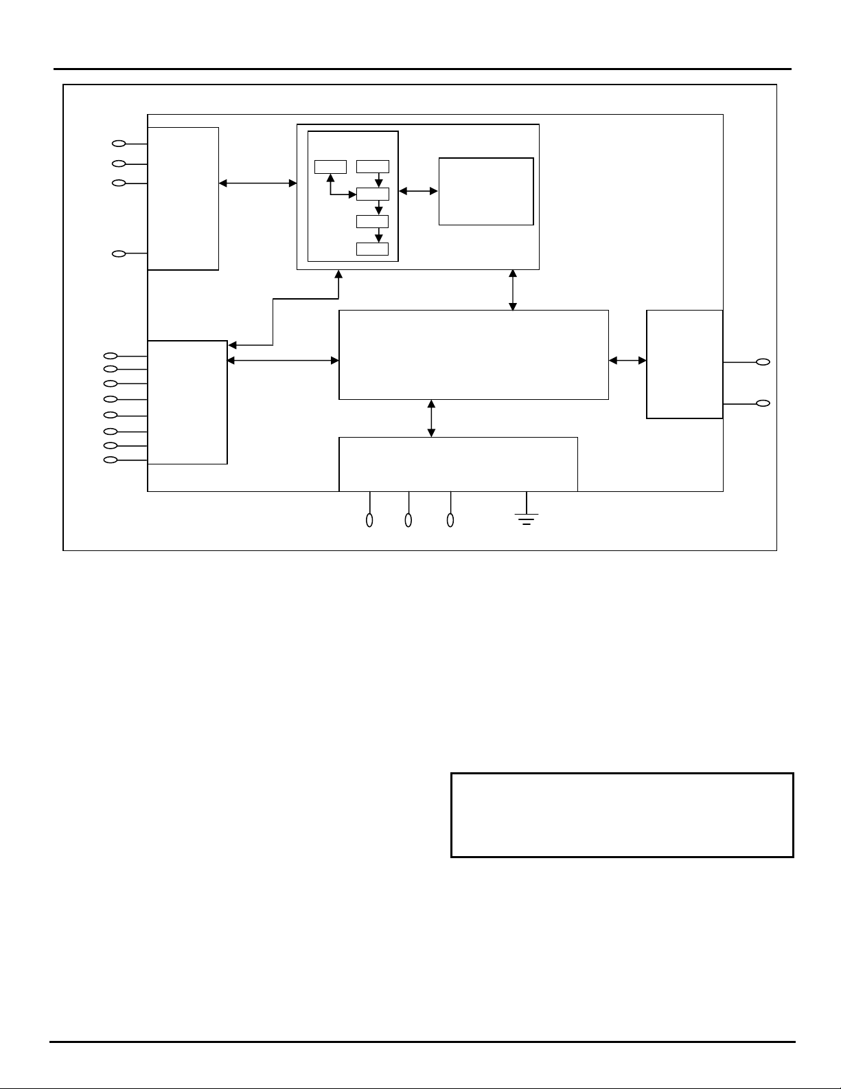
iMODEM EVALUATION BOARD
Cermetek manufactures a companion evaluation board
that is designed to simplify the hardware connections
required to program the iModem as well as providing a
reliable platform to assist with system level debugging.
Contact Cermetek and ask for the CH21XX iModem
Evaluation Board.
iMODEM CONTROL METHODOLOGIES
The iModem receives @T®commands from the host
processor or receives an event status flag on the Send
Email Control Pin (Pin #6) and proceeds to dial up the
local POP, log on to the internet, authenticate and verify
the user ID and password, and either sends or retrieves
email depending on the command/status flag received.
For CH2124/60 products, see Table 1 for a summary of
available @T®commands.
The iModem Family offers a variety of internet
communication features ranging from simple on
demand event triggered email transmission to full send
and retrieve email capability. User Control of the
internet communication activity of the iModem device
typically falls into one of the following basic control
strategies:
1. Fully Autonomous or event driven pin control
requiring no host processor intervention. A pre-
stored message is sent on a pin transition
(CH2124/60).
2. Semiautonomous control, requiring one command to
be issued from the host processor. A pre-stored
message is sent on command.
3. Complete host intervention and supervision requiring
each command to be issued from the host.
Message is constructed and sent in real time.
Fully Autonomous On Demand Event Driven
Control. This is the simplest method of operational
control. Application of a 50ms TTL Low going pulse or
level to the Send Email Control pin (Pin # 6) will cause
the CH2124/60 iModem to send an email using its
internal internet configuration profile. This profile is pre-
programmed at the factory and can be modified by the
user as necessary. No host processor intervention is
required. The DTE serial interface is not required for
fully autonomous on demand or event driven control.
The CH2124/60 iModem will abort email related
activities and return to the idle state if a low going TTL
pulse is presented to the SEND Email Control Pin (Pin
# 6) at any time during or after initiation of email send.
Semi-Autonomous Control. This method requires a
minimal amount of host processor intervention and
requires that the DTE serial port be operational. Semi-
autonomous control is a special case of full Host
Supervised Control and relies on the preprogrammed
default internet configuration profile contained within the
iModem. Initiation of an email activity occurs with the
issuance by the host processor to the iModem the
appropriate @T®command to send/retrieve/delete
email. PSTN dial-up, logon, authentication and email
transmission, retrieval, and/or deletion are performed
automatically by the iModem in the same fashion as for
the Fully Autonomous On-Demand control method
described above.
Host Supervised Control. This method is the most
flexible, but requires issuance by the host processor of
the necessary @T®commands in the required order
from the host processor. When choosing an
implementation scheme utilizing a host processor, the
host controls the iModem by using Cermetek @T®
commands. These commands are similar to the
standard Hayes AT command set.
Although the DTE serial port is required to be
operational for this method of control, an additional
feature of this method is the ability of the host to over-
ride the preprogrammed parameters (including the
email message content) by simply entering the
applicable information using the appropriate @T®
Command.
Delete Email. The user may selectively delete any
email message (by specifying the message number) or
delete all messages cached on the POP3 server.
Email and Internet Activity Status. The CH2124/60
provides activity status messages on the iModem’s
serial port. These status messages consist of a series
of ASCII characters. Some examples are: BAD
MESSAGE NUMBER, CONNECT, HANGING UP,
MESSAGE ACCEPTED, MESSAGE DELETED. For a
more detailed discussion of CH2124/60 status
messages, refer to Cermetek Application Note # 155,
@T®Command Set Description and Usage For
CH2124/60 iModems.
Back-up and Alternative POP access Phone
Numbers. Cermetek iModem products allow usage of
an alternative local access POP phone number or, if
available, a 1-800 number, should the iModem fail to
connect to the primary POP. The user can establish
the number of attempts made to the primary POP
before the back up POP is attempted.

Cermetek Microelectronics, Inc. High Speed Internet Modem Family
2005 Cermetek Microelectronics, Inc. Page 4 Document No. 607-0017 Revision I1 (05/05)
Figure 2. Functional Block Diagram of Cermetek CH2124/60 iModem Products.
DESCRIPTION OF FUNCTIONAL BLOCKS AND
DISCUSSION OF BASIC OPERATIONS
Each CH21XX iModem product consists of the following
functional blocks:
1. µP controller with Network Protocols and Flash
ROM.
2. Serial interface buffer.
3. Input/Output interface circuitry.
4. Internal modem (V.90 or V.22bis).
5. Modem interface circuitry.
6. DAA (Data Access Arrangement) PSTN interface.
Figure 2 contains a schematic drawing illustrating the
interconnectivity of the various functional blocks
comprising the CH21XX iModem products.
Each iModem performs the following internet
connectivity functions automatically:
1. Dials local POP and Connects to ISP.
2. Authenticates user ID and logs onto the internet.
3. Sends (or Retrieves) email to (from) the server
address/name specified using the ISP’s SMTP
(POP3) Mail Server.
4. Terminates ISP session after all data is sent (or
retrieved).
5. The CH2124/60 sends an ASCII MESSAGE
ACCEPTED activity response message and sends
a TTL LOW Pulse to Pin 8 indicating that the ISP
Mail Server has accepted the email message.
Control of the internet capabilities of the iModem can be
either event driven or initiated and controlled by a
system level host processor. Refer to Table 3 for a
complete set of pin descriptions.
When not utilized in the internet connectivity role, the
iModem will function as a standard analog modem.
KEY FEATURE
The user has complete control of the level of
autonomy the iModem exercises in the user’s
application. This is a unique feature of Cermetek’s
iModem products.
µP Controller. The µP controller performs the required
internet operations by interpreting each specific @T®
command and executing the appropriate internet
commands. The necessary internet protocol firmware
is resident in flash ROM. The @T®commands function
as an extension to the industry standard Hayes AT
command set.
PSTN
Input 1
Input 2
SEND EMAIL
CONTROL
PIN INPUT
SENSE
AND
OUTPUT
PINS
Interface
Circuitry
SERIAL
INTERFACE
V-24
EIA-232-E or
UART
MODEM
V.90 (CH2160/65)
V.22bis (CH2124)
MODEM INTERFACE
DAA
CH21XX
RXD
RTS
DCD
DSR
RI
CTS
TXD
DTR
TIP
Ring
EMAIL
ACCEPTED
INDICATOR
PIN
Flash ROM
32Kx8
Network
Protocol
SMTP
TCP
IP
PPP
POP 3
µ
P
RST SPK +5V GND

Cermetek Microelectronics, Inc. High Speed Internet Modem Family
2005 Cermetek Microelectronics, Inc. Page 5 Document No. 607-0017 Revision I1 (05/05)
Internal Modem. The internal modem is used to
establish a data connection with the ISP. The CH2160
contains a V.90 internal modem while the CH2124
contains a V.22bis internal modem. The internal
modem can be controlled with Hayes AT commands
and is compatible with industry standard
communication software. Refer to Cermetek
publication, AT Commands and S-Registers, for a more
detailed discussion of the Hayes AT commands
supported by the iModem product family.
When operating in standard analog modem mode, the
maximum Data Terminal Equipment (DTE)/Host system
communication speed is established by the maximum
speed available from the DTE/Host and is not limited by
the iModem product.
IMPORTANT NOTICE
AS DELIVERED FROM THE FACTORY, all @T®
command communication between the CH2160
(CH2124) iModem and the host processor is
conducted over the serial interface at 57.6/19.2kbps
(2400bps).
CH21XX DTE Speed. AS DELIVERED FROM THE
FACTORY, the CH2160 iModem will only communicate
with the DTE at 57.6kbps and the CH2124 at 2400bps.
However, the user may modify the DTE speed with the
appropriate @T®commands. Refer to Application Note
# 155, @T®Command Set Description and Usage For
CH2124/60. When the user changes the DTE
communication speed to any speed other than the
default value set of the factory, the user must ensure
that the DTE supports the speed selected. Failure to
do so could adversely affect communication with the
iModem device or, worst-case, disable communication
with the internal µP controller. Refer to Application
Note # 158, Cermetek iModem Caveats and Definitions,
for a more detailed discussion of this issue.
IMPORTANT NOTE
Cermetek recommends a minimum of 50ms inter-
character delay when sending commands to the
CH2124/60 iModem. Failure to do so could result in
unpredictable performance.
Refer to Cermetek’s High Speed Modem and FAX
Family product data sheet for a complete Description of
the internal modem’s capabilities and functions.
Serial Host Interface Buffer. The iModem utilizes a
serial V.24 EIA 232-E 5V interface to communicate with
the internal modem and to communicate with the
internal µP.
Telephone Line Interface or DAA. The iModem
family includes a unique low distortion DAA designed
for optimal performance over all PSTN line conditions
thereby achieving the most reliable and best
performance PSTN connections.
The CH21XX iModem family is designed to meet North
American telephone standards as set by FCC Part 68
(USA) and Industry Canada CS-03 Part I (Canada).
Each iModem product is shipped from the factory with
an FCC label indicating the FCC registration number
and ringer equivalent. The PSTN line interface is
UL1950 and CSA listed. Consequently, the iModem
family of products satisfies U.S. and Canadian
requirements, and will meet other international approval
agency requirements that specify these levels of
isolation.
IMPORTANT NOTICE
If the user wants to change the DTE/Host
communication speed to any speed other than the
factory set speed of 57.6kbps for the CH2160 or
2400bps for the CH2124, the user must first change
the DTE speed of the iModem using the appropriate
all @T®commands before changing the DTE/Host
speed. Refer to Application Note # 158, Cermetek
iModem Caveats and Definitions, for a more detailed
discussion of this issue.

Cermetek Microelectronics, Inc. High Speed Internet Modem Family
2005 Cermetek Microelectronics, Inc. Page 6 Document No. 607-0017 Revision I1 (05/05)
Table 1. Summary of CH2124/60 Allowed @T®Commands.
Command Notes Description
@T[A1][=n]1,2,3,4 Enter destination email address, n. Maximum length is 34 ASCII characters.
@T[D][] 1,2,7,12 Dialup ISP and send pre-configured Input Port Status email. Message type sent is specified
by @TJn command or by K8 parameter for firmware versions 1.262 or greater.
@T[DG][n]1,2,12 Dial preprogrammed ISP and Retrieve mail message from preprogrammed email address.
Message number must be specified, n=1 to 99.
@T[DK][n]1,2,12 Dial preprogrammed ISP and Delete mail message n.
n=aa Where aa is the message number.
n=aa-bb will delete message number aa through bb (inclusive).
n=* will delete all messages.
@T[DM1][] 1,2,3,4,
7,12
Dialup ISP and send user defined email message regardless of message type specified by
@TJn command.
@T[E1][=n]1,2,3,4 Enter local or “FROM:” email address, n.
@T[H][] 1,2 Directs remotely accessed iModem connected via Remote Dial-up Access to terminate
access session and hang-up.
@T[J][0]1,2,7,12 Establish email message type to be sent when iModem SEND pin is activated or the @TD
command issued. J0 will select the Input Port Status message or by K8 parameter for
firmware versions 1.262 or greater.
@T[J][1]1,2,7,12 Establish email message type to be sent when iModem SEND pin is activated or the @TD
command issued. J1 will select the User Defined message or by K8 parameter for firmware
versions 1.262 or greater.
@T[K0][=n]1,2,6 Select PAP Authentication Protocol:
n=01 allows PAP only. (DEFAULT)
n=7D allows CHAP or PAP. (CHAP NOT SUPPORTED)
@T[K1][=n]1,2,6 Set the number of dial-up attempts. Auto re-dial enabled for K1>01. Specified in HEX. n=01
allows initial dial-up attempt only (default).
n=0E allows 15 dial-up attempts (maximum per FCC).
@T[K2][=n]1,2,6 Set the number of minutes, n, between auto-redials. Specified in HEX.
n=01 1 minute between re-dial attempts (default).
n=FF 255 minutes between re-dial attempts (maximum).
@T[K3][=n]1,2,6,10 Set the number of MESSAGE ACCEPTEDs required to exit auto-redial mode. Specified in
HEX.
n=01 1 MESSAGE ACCEPTEDs to exit auto re-dial (default).
n=FF 255 “accepted message” to exit auto re-dial (maximum).
@T[K4][=n]1,2,6,8 Select login method for User Defined message. K4 affects the currently ACTIVE ISP
CONFIGURATION profile only:
n=01 PPP login only. PPP protocol used for email data packets.
n=02 Enables ASCII Text Login. PPP protocol used for email data packets. Message sent
using TCP/IP.
n=03 Unix Shell login. No PPP protocol.
@T[K8][=n]1,2,6 Select Email Message type to be sent when SEND PIN is set TTL low. Replaces @TJ0 and
@TJ1 for firmware revisions 1.262 and greater:
n=30 Send Input Port Status message.
n=31 Send User Defined message. (Default)

Cermetek Microelectronics, Inc. High Speed Internet Modem Family
2005 Cermetek Microelectronics, Inc. Page 7 Document No. 607-0017 Revision I1 (05/05)
Table 1. Summary of CH2124/60 Allowed @T®Commands (Continued).
Command Notes Description
@T[K10][=n]1,2,6,9 Select DTE Baud rate:
n=01 Select DTE baud rate 115200.
n=02 Select DTE baud rate 57600. (Default CH2160)
n=11 Select DTE baud rate 38400.
n=12 Disabled.
n=13 Select DTE baud rate 9600.
n=14 Select DTE baud rate 4800.
n=15 Select DTE baud rate 2400. (Default CH2124)
n=16 Disabled.
@T[K11][=n]1,2,6,9,
14
Enable/Disable Remote Dial-up Access. For ngreater than 00, Remote Dial-up Access is
enabled and nspecifies the number of rings required before iModem will answer the
incoming call. Specified in HEX.
n=00 Disable Remote Dial-up Access.
n=02 Enable Remote Dial-up Access to answer after 2 ring (minimum allowed) (Default)
n=FF Enable Remote Dial-up Access to answer after 255 rings (maximum allowed).
@T[LM][=n]1,2 Enter POP3 Login name, n.
@T[L1][=n]1,2 Enter ISP Login name, n.
@T[M1][=n]1,2 Enter user defined email message, n. End with <CR><LF>.<CR><LF>. The mail message
must be entered after all other ISP parameters have been set. Additionally, any carriage
return <CR> (HEX ØD) included in the message is interpreted as a carriage return <CR> line
feed <LF> (HEX ØD ØA). This is for compatibility with commercial terminal emulation
programs. The message length is currently limited to 125 ASCII characters. Blanks or
spaces are allowed and count as 1 character per each occurrence. The entered message is
stored in message memory location M1.
@T[N1][=n]1,2 Enter local access phone number for ISP, n.
@T[OP1][=n]1,2 Enter POP3 server IP HEXIDECIMAL address, n.
@T[OS1][=n]1,2 Enter SMTP server IP HEXIDECIMAL address, n.
@T[PW][=n]1,2 Enter Dialup Password. Maximum length is 15 alphanumeric ASCII characters.
@T[PM][=n]1,2 Enter POP3 Password. Maximum length is 16 alphanumeric ASCII characters.
@T[P1][=n]1,2 Enter password for ISP, n. Blanks or spaces are not allowed.
@T[Q][=n]1,2,3,4 Terminate iModem mode of remotely accessed iModem during Remote Dial-up Access
session. Switch to standard analog modem mode while maintaining current Remote Dial-up
Access session.
@T[S1][=n]1,2,3,4 Enter email subject line, n. The subject line length is currently limited to 16 ASCII characters.
Blanks or spaces are allowed and count as 1 character per each occurrence. The same
subject line is used for both the Input Port Status message and the User Defined message.
@T[U1][=n]1,2 Enter iModem Device Name. No special characters allowed (i.e., %, *). Maximum length is 16
alpha-numeric ASCII characters.
@T[Z][] 1,2,11 Restores factory set profile (i.e., phone number, username, password, SMTP mail server
address, iModem local email address subject and message body).
@T[Z][n]1,2,11 Set current ACTIVE ISP profile (i.e., phone number, username, password, SMTP mail server
address, iModem local email address subject and message body) from factory set profiles.
n=0 Restore factory set ISP profile. Same as @TZ.

Cermetek Microelectronics, Inc. High Speed Internet Modem Family
2005 Cermetek Microelectronics, Inc. Page 8 Document No. 607-0017 Revision I1 (05/05)
Table 1. Summary of CH2124/60 Allowed @T®Commands (Continued).
Notes For Table 1.
1. Use the exact syntax as indicated in Table 1 above.
2. Each command line has the following format:
@T[command][=data field]<CR><LF>
Any information listed in bold is a required portion of the command string. Brackets [] not in bold are intended to
serve as delimiters only and are not part of the required command string. All embedded spaces are ignored
except in the data field.
3. For the case of the User Defined email message (i.e., message sent using the @TDM1 command), the @TM1
must be the last ISP parameter modification command executed prior to executing the @TDM1 the command.
This means the @TM1 command must be executed after the @TA1, @TE1, @TS1 and @TU1 commands.
This programming sequence is necessary because the @TM1 command forces the iModem to compose the
entire message and store the complete message (including headers) into flash memory prior to initiating ISP
dialup. Failure to do this will cause unpredictable results.
4. For the case of the Input Port Status email message (i.e., message sent using the @TD command). When the
message type selection is @TJ0 (or @TK8=30, as appropriate), the @TM1 command execution requirements
of Note 3 above DO NOT apply.
5. Parameter must be specified as one ASCII alphanumeric character.
6. Parameter must be specified as two alphanumeric characters. Use a leading 0, if necessary.
7. Effective with iModem Firmware Revisions 1.262 or greater, the @TJ0 and @TJ1 commands have been
replaced with K8 parameter modifiable with the @TK8 command.
8. Dial-up Unix Shell account access is NOT currently supported on the iModem Network ISP.
9. Although the @TK10 command allows the DTE communication speed of the CH2160 iModem devices to be
changed, the user must ensure that the DTE communication speed selected is actually supported by the DTE.
Failure to due so could inadvertently disable communication with the iModem device.
10. If the maximum number of MESSAGE ACCEPTEDs is set to a value greater than the number of auto re-dial
attempts, the iModem will auto re-dial the number of re-dial attempts specified by the auto re-dial parameter
(K1). Under no circumstances will auto re-dial exceed the number of re-dial attempts specified by parameter
K1.
11. The @TM1 command must be executed after the @TZ, @TZ0 and @TZ1 commands. This is required to
“rebuild” the email message including headers. Failure execute the @TM1 command will cause errors in the
header creating leading to unpredictable email transmission results.
12. NOT supported during Remote Dial-up Access session.
13. If TK5=02 and TK1=01, the email message will be sent using the Back Channel feature on the first dial attempt.
14. Must set K11=00 to allow the CH2124/60 product to answer as a remote modem. This disables the Remote
Dial-up Access feature.

Cermetek Microelectronics, Inc. High Speed Internet Modem Family
2005 Cermetek Microelectronics, Inc. Page 9 Document No. 607-0017 Revision I1 (05/05)
Table 2. Summary of CH2124/60 iModem @TResult Messages.
Result Message Explanation of Result Message
BAD MESSAGE NUMBER 1. Occurs during retrieval (@TGn command) or during deletion (@TDKn
command) when message number specified does not exist on POP3
server.
CHAP ERROR 1. Occurs when CHAP protocol error occurs during login. (Not
Supported).
CONNECT 1. Successful dialup and ISP connection.
ERROR 1. Occurs when errors in data field are encountered.
HANGING UP 1. Occurs after PSTN line release.
MAILBOX BUSY 1. Occurs when POP3 server connection is in use by another device
logged in using the same User ID.
2. Occurs when POP3 server connection was not properly terminated and
user attempts to reconnect within 12 minutes of previous connection.
3. Occurs when POP3 server detects error in specified POP3 Login and/or
Password.
MESSAGE ACCEPTED 1. Occurs after successful email transmission and after receipt of
MESSAGE ACCEPT status from ISP SMTP mail server.
MESSAGE DELETED 1. Occurs after successful deletion of specified message number(s).
NO CONNECT 1. Occurs when PSTN line is released after unsuccessful dialup and/or
unsuccessful ISP negotiation and/or unsuccessful SMTP server
negotiation.
NO DIALTONE 1. Occurs after unsuccessful dialup and iModem determines that cause of
unsuccessful dialup is lack of dial tone.
NOT IN IMODEM MODE 1. Occurs when verbose result message responses are disabled. When in
this state, @T commands will not be executed.
OK 1. Successful execution of @T commands except @TD and @TDM1.
PASSWORD ERROR 1. Occurs when error in specified password is detected.
PASSWORD OK 1. Occurs after successful logon to specified ISP account.
POP3 REQUESTS TERMINATION 1. Occurs when the POP3 server determines that the user is already
connected to the POP3 server. POP3 requests that the user terminate
attempted POP3 connection.
RETRIEVAL COMPLETE 1. Occurs after successful retrieval of specified POP3 message number.
SERVER CLOSED 1. Occurs when POP3 server connection is terminated.
BUSY 1. Occurs when called POP is busy.

Cermetek Microelectronics, Inc. High Speed Internet Modem Family
2005 Cermetek Microelectronics, Inc. Page 10 Document No. 607-0017 Revision I1 (05/05)
Table 3. Summary of Query Commands
Command Description/Function
Commands To Query iModem Parameters
@TA1? Display destination address.
@TE1? Display “FROM” address.
@TK? Display all K parameters.
@TL1? Display user name.
@TM1? Display User Defined email message.
@TN1? Display local access POP phone number.
@TOP1? Display POP3 server IP address.
@TOS1? Display SMTP server IP address.
@TPW? Display Dial-up password.
@TPM? Display POP3 password.
@TP1? Display ISP password.
@TS1? Display email subject.
@TU1? Display email recipient “TO” name.
Commands To Interrogate iModem
Command Function
@TI Display iModem product type and firmware revision.
@TV Displays ISP configuration profile and User Defined email message.
@TV0 Displays ISP configuration profile and User Defined email message.
@TV1 Displays Input Port Status message.

Cermetek Microelectronics, Inc. High Speed Internet Modem Family
2005 Cermetek Microelectronics, Inc. Page 11 Document No. 607-0017 Revision I1 (05/05)
Pins 1 and 2 function as both input and output
connections to the PSTN. To maximize field reliability
in hostile environments, to ensure UL compliance, and
also optionally for FCC part 15 compliance, these two
pins may be routed through an external network such
as that briefly described in figure 3 or as described in
more detail in Cermetek Application Note # 126,
Supplemental PSTN Line Protection.
PHONE LINE CONNECTION GUIDELINES
1. The iModem must be mounted in the final
assembly such that it is isolated from exposure to
any hazardous voltages within the assembly.
Adequate separation and restraint of cables and
cords must be provided.
The circuitry from the iModem to the telephone
interface must be provided in wiring that carries
no other circuitry other than that specifically
allowedin the FCC rules (such as A and A1
leads).
2. Connection to the PSTN line should be made
through an RJ-11C jack.
3. PCB traces from the iModem’s RING and TIP
pins to the RJ-11C jack must be 0.1 inch spacing
or greater to one another and 0.2 inch spacing or
greater to all other traces. The traces should
have a nominal width of 0.020 inches or greater.
4. The RING and TIP PCB traces should be as
short as possible and oriented to prevent
coupling with other high speed or high frequency
signals present on the host circuit PCB.
5. No additional circuitry other than that shown in
Figure 3 may be connected between the iModem
module and the RJ-11C jack. Doing so will
invalidate the conveyed FCC approval.
6. The iModem, the RJ-11C jack, the interfacing
circuitry and all PCB traces must be contained on
a PCB with a 94 V-0 flammability rating.
7. The supplied FCC registration label must be
applied visibly on the outside of the product.
8. The product’s User Manual must provide the user
with instructions for connection and use as
recommended in the FCC Registration Section
below.
CANADIAN APPROVALS
The iModem family is approvable for use by DOT to
Industry Canada CS-03 Part I. However, per
Canadian procedures, approval can only be granted
after the iModem has been installed into the end
product. Typically, Canadian approval is obtained by
submitting the final end product to an independent test
house or consultant for evaluation. The test
house/consultant then forwards the test results and
applicable documents to the regulatory agency.
Cermetek offers a list of consultants to assist with this
process.
iMODEM HANDLING AND ASSEMBLY
RECOMMENDATIONS
The iModem contains static-sensitive components and
should only be handled by personnel and in areas that
are properly protected against static discharge.
There are two mounting techniques that are
recommended for physically connecting the iModem to
a PCB:
1. Direct soldering.
2. Sockets.
Direct Soldering. The iModem may be wave
soldered onto a circuit card. All iModem products are
sealed and will not be harmed by industry standard
wave soldering processes.
Socketing. The socket approach to mounting
eliminates cleaning and desoldering concerns. When
the socket is used, it must make a solid connection to
all pins. Failure to do so will cause unreliable or
intermittent operation. Also, steps should be taken to
assure that the module remains tightly seated in the
socket after the end product is shipped. Cermetek
recommends the 50 pin strip socket CES-150-01-T-S
by Samtec. Refer to Application Note# 130, Summary
of Recommend Supplies, for a list of supplies and
associated contact information.
FCC REGISTRATION
All CH21XX iModem products are registered with the
FCC under Part 68. To maintain the validity of the
registration, notice of the restrictions the FCC places
on the iModem and its use must be served to the end
user of the product containing the iModem.
In addition to restriction notification, the FCC requires
that Cermetek make all repairs to all products in the
iModem family. If repairs are necessary after
installation of the iModem and the end product has
been delivered to the end user, the end product must
be returned to the end product supplier where the
iModem can be removed and then forwarded to
Cermetek for repair. The following notice is
recommended and should be included in the end
product’s user manual.

Cermetek Microelectronics, Inc. High Speed Internet Modem Family
2005 Cermetek Microelectronics, Inc. Page 12 Document No. 607-0017 Revision I1 (05/05)
FOR YOUR USER’S MANUAL
The Part 68 rules require the following (or equivalent)
be provided to the end user of the equipment
containing an iModem device.
Type of Service: The (insert end product name) is
designed to be used on standard device telephone
lines. It connects to the telephone line by means of a
standard jack called the USOC RJ-11C (or USOC
RJ45S). Connection to telephone-company-provided
coin service (central office implemented systems) is
prohibited. Connection to party lines service is subject
to state tariffs.
Changes in Attestation Procedure for Plugs and
Jacks: (Name of applicant) attests that the network
interface plugs or jacks used on this equipment comply
with and will continue to comply with the mechanical
requirements specified in Part 68, Sub-part F,
specifically the dimensions, tolerances and metallic
plating requirements. The compliance of these
connectors will be assured by purchase specifications
and incoming inspection. Documentation of such
specifications and/or inspections will be provided by
the FCC within 30 days of their request for the same.
Telephone Company Procedure: The goal of the
telephone company is to provide the best service it
can. In order to do this, it may occasionally be
necessary for the telephone company to make
changes to their equipment, operations or procedures.
If these changes might affect service provided to the
users or the operation of the user’s equipment, the
telephone company will give the user notice, in writing,
to allow the users to make any changes necessary to
maintain uninterrupted service.
In certain circumstances, it may be necessary for the
telephone company to request information from the
users concerning the equipment which the user has
connected to the telephone line. Upon request of the
telephone company, provide the FCC registration
number and the ringer equivalence number (REN);
both of these items are listed on the equipment label.
The sum of all of the REN’s on the user’s telephone
lines should be less than five in order to assure proper
service from the telephone company. In some cases,
a sum of five may not be useable on a given line.
Consult your telephone provider.
If Problems Arise: If any of the user’s telephone
equipment is not operating properly, the user should
immediately remove it from the user telephone line, as
it may cause harm to the telephone network. If the
telephone company notes a problem, they may
temporarily discontinue service. When practical, they
will notify the user in advance of this disconnection. If
advance notice is not feasible, the user will be notified
as soon as possible.
When the user is notified, the user will be given the
opportunity to correct the problem and informed of
their right to file a complaint with the FCC. Contact the
local telephone service provider if any questions arise
concerning the telephone service.
In the event repairs are ever needed on the (insert
your product name), they should be performed by
(insert your company name), or an authorized
representative or (insert your company name). For
information contact: (insert your company address).

Cermetek Microelectronics, Inc. High Speed Internet Modem Family
2005 Cermetek Microelectronics, Inc. Page 13 Document No. 607-0017 Revision I1 (05/05)
Table 3. iModem Family Pin Description.
PIN NAME I/O FUNCTION
1
RING
I/O
Directly connects to the telephone line’s Ring lead through a user supplied RJ-11C jack.
2
TIP
I/O
Directly connects to the telephone line’s TIP lead through a user supplied RJ-11C jack.
3
NC
---
NO CONECTION
4
NC
---
NO CONECTION
5
SPK
O
SPEAKER. Audio output for speaker. See speaker control diagram.
6
SEND
I
SEND EMAIL. Active Low. A low pulse will send an email. The modem will go off hook,
dialup an ISP, send the email and hang up. The SEND pin must be tied high when not in
use. Pulse should be 50msec minimum.
7
IN 1
I
Input. TTL High or Low input pin. The logic level of this input pin is reported in the email
message.
8
SENT
O
EMAIL SENT. Active Low. A low pulse is output on this pin to indicate that an email sent
by the iModem has been accepted by its ISP. The pulse is low for 50ms minimum. See
figure 8.
9
IN 2
I
Input. TTL High or Low input pin. The logic level of this input pin is reported in the email
message.
10
TXD
I
TRANSMIT DATA. Serial transmit data input. Marking, or a binary 1 condition is indicated
by a HIGH.
11
RXD
O
RECEIVE DATA. Serial Receive data output. Received marking or a binary 1 condition is
indicated by a HIGH.
12
NC
---
NO CONECTION
13
DTR
I
DATA TERMINAL READY INPUT. Active LOW. Switching off DTR can either return
modem to command state, disconnect phone call, or reset modem. DTR should be set
LOW when not in use.
14
DSR
O
DATA SET READY. LOW indicates handshaking with a remote modem in progress,
and/or the data carrier of a remote modem has been detected.
15
RI
O
RING INDICATION. This signal follows the frequency of the ringing signal and is normally
about 20 to 40 Hz for 2 seconds on with 4 second off.
16
CTS
O
CLEAR-TO-SEND. Output always LOW. Reserved for flow controls with FAX option. Not
active, let float.
17
DCD
O
DATA CARRIER DETECT. LOW indicates a data carrier from a remote modem has been
detected. Must enable with AT&C1 Hayes command.
18
NC
---
NO CONECTION
19
VCC
---
DC SUPPLY. 5V ± 5% required.
20
GND
---
GROUND. Note: Noise should be less than 25mV peak to peak.
21
RST
I
RESET. Active HIGH. This input must be asserted HIGH for at least 10ms to reset the
modem. RESET is then returned to LOW for normal operation. If no system reset is
available, let this pin float to enable internal reset.
22
RTS
I
REQUEST TO SEND. Active Low. Used for flow control. Should be tied Low when using
SEND pin and when using @T commands for CH2160 only. DO NOT CONNECT for
CH2124.

Cermetek Microelectronics, Inc. High Speed Internet Modem Family
2005 Cermetek Microelectronics, Inc. Page 14 Document No. 607-0017 Revision I1 (05/05)
Figure 3. PSTN Line Interface for all iNet Appliance Products.
1. Currently Limiting PSTN Protection Line
Device.
Currently limiting devices are mandatory to meet
UL safety standards. To maintain conveyed FCC
Part 68 approval, the current limiting components
identified as F1 and F2 in dashed Box #1 must
also survive FCC Part 68 surge testing. Refer to
Cermetek Application Note #126, Supplemental
PSTN Line Protection, for more details. Refer to
Application Note # 130, Summary of Recommend
Suppliers, for a list of suppliers and associated
part numbers.
A. A PTC (rated at 0.15 amps) is preferred
because it resets automatically upon removal
of the current flow. Fuse devices are also
acceptable. Refer to Application Note #130
for a complete list of recommended vendors
and associated part numbers.
B. Resistors (10Ωcarbon film or 1/8 watt
minimum) may be used in Canada, as
Canada has no requirements that PSTN
equipment be operational after a Type B
surge test.
C. Although CSA CS-03 Part 1 (Canada) follows
the requirements of FCC Part 68 (USA),
Cermetek recommends contacting DOT
(Canada) and/or a certified independent lab to
verify compliance. For Canada, use either
10Ωresistors (carbon film or SMD parts 1/8
watt minimum) as described in paragraph B
above.
2. Over Voltage and Lightning Protection.
A. Surge Protection is provided by internal
circuitry (see Figure 3). No additional external
components are required to maintain
conveyed FCC Part 68 approval.
B. In most environments, 2 terminal surge
suppressors are adequate. For severe
environments, use an external 3 terminal
device with an earth ground.
3. EMI/RFI Suppression.
No external EMI/RFI noise suppression circuitry is
required to maintain conveyed FCC Part 68
approval. However, additional suppression, if
required for other reasons, may be added as
described below in Sections 3A-3B without
adversely affecting FCC Part 68 approval.
A. To provide adequate EMI/RFI suppression,
the capacitor/inductor network contained in
dashed Box #3 should be located as close to
the RJ-11C jack as possible. Further, this
network should be provided with an excellent
ground path to the chassis.
B. Capacitors C1 and C2 should not exceed
0.005µf. They must have a rating of 1.5KV
and typically are 0.001µf ± 20%. Inductors L1
and L2 may be either individual inductors or a
dual inductor. Refer to Application Note #130
for a complete list of recommended vendors
and associated part numbers. For UL
applications, choose capacitors and inductors
that are UL 1950 listed. The actual values of
the components used may vary depending on
the end product design.

Cermetek Microelectronics, Inc. High Speed Internet Modem Family
2005 Cermetek Microelectronics, Inc. Page 15 Document No. 607-0017 Revision I1 (05/05)
Table 4. Analog Characteristics.
NAME TYPE CHARACTERISTICS VALUE
SPK O(DF) Minimum Load 300ohm
Maximum Capacitive Load 0.01µf
Output Impedance 10ohm
Output Voltage 2.5 ± 1.6V
D.C. Offset <20mV
Table 5. Summary of CH2124/60 iModem Family of Products.
Model Summary of Features Operating Temperature
CH2124 2 Input Sense Pins, Send and Retrieve Emails. Email Send Control Pin,
Full Function, V.22bis, 2400bps, FCC Part 68 Approved, UL1950 listed.
0°C to 70°C
CH2160 2 Input Sense Pins, Send and Retrieve Email. Email Send Control Pin
Full Function, V.90, 56Kbps, FCC Part 68 Approved, UL 1950 listed.
0°C to 70°C
Figure 4. Example Circuit for illumination of Email Accepted LED for CH2124/60. This circuit is not needed
for the CH2165 product.
CLEAR LED
74LS74
SET
CLR
D
SET
CLR
D
C
Q
Q
300
Ω
Vcc
4.7K
Ω
Vcc
4.7KΩ
CH21XX
SENT
74HCT74
Vcc
+
10µf
8
-

Cermetek Microelectronics, Inc. High Speed Internet Modem Family
2005 Cermetek Microelectronics, Inc. Page 16 Document No. 607-0017 Revision I1 (05/05)
Table 6A. CH2124 iModem Electrical Specifications.
Symbol Characteristic Min. Typ. Max. Units
VCC Positive Supply Voltage 4.5 5.0 5.5 V
ICC Off Hook Nominal Operating Current @
VCC= 5.5V when modem is Off Hook
30.0 50.0 mA
VIH High Level Input Voltage @ 5.0V 2.0 3.5 V
VIL Low Level Input Voltage @ 5.0V 1.0 2.2 V
VT+ Positive Hysteresis Threshold for RESET Pin 2.6 V
VT- Negative Hysteresis Threshold for RESET Pin 2.4 V
VOH High Level Output (IOH= 0.5mA)* 2.4 V
VOL Low Level Output (IOl= 1.6mA)* 0.6 V
IIN Input Leakage Current (TXD, DTR, RTS, IN1,
IN2, SEND
100 uA
IIL Input Current (RST) 580 uA
CPCapacitive Load (TXD, DTR, RTS)
Capacitive Load (RTS)
10
8
pF
pF
Table 6B. CH2160 iModem Electrical Specifications.
Symbol Characteristic Min. Typ. Max. Units
VCC Positive Supply Voltage 4.5 5.0 5.5 V
ICC Off Hook Nominal Operating Current @
VCC= 5.5V when modem is Off Hook
120.0 mA
VIH High Level Input Voltage @ 5.0V 2.0 3.5 V
VIL Low Level Input Voltage @ 5.0V 1.0 2.2 V
VT+ Positive Hysteresis Threshold for RESET Pin 2.5 V
VT- Negative Hysteresis Threshold for RESET Pin 1.2 V
VOH High Level Output (IOH= 0.5mA)* 2.4 V
VOL Low Level Output (IOl= 1.6mA)* 0.6 V
IIN Input Leakage Current (TXD, DTR, RTS, IN1,
IN2, SEND
100 uA
IOH Input Current (RST) 580 uA
CPCapacitive Load (TXD, DTR, RTS)
Capacitive Load (RTS)
10
8
pF
pF
IMPORTANT NOTE
Cermetek recommends a minimum of 50ms inter-character delay when sending commands to the CH2124/60
iModem. Failure to do so could result in unpredictable performance.

Cermetek Microelectronics, Inc. High Speed Internet Modem Family
2005 Cermetek Microelectronics, Inc. Page 17 Document No. 607-0017 Revision I1 (05/05)
Table 7A. CH2124 iModem Electrical Specifications.
Parameter Minimum Typical Maximum Units Comments
Off Hook Impedance 20 Mohm
Trans Hybrid Loss 25 dB 600 Ohm, RXA, TXA
Ring Voltage Loop 15 VPP On 48VDC line voltage
for sustained periods
Line Loop Current - (Off
Hook)
20 60 mA
Return Loss @ 1000 Hz 15 dB 600 Ohm
Ring Frequencies 18 20 30 Hz
Receiver Insertion Gain -0.5 0.0 +0.5 dB
Transmit Power -9.5 dBm 600 Ohm- Data Mode
First Character After Reset
See Note 1
10.0 sec Delay
Inter Character Delay 20 50 msec Between all command
characters
Command Delay 100 200 msec Between all AT
commands
Minimum Reset Pulse 10 msec If user supplied
Note: 1. All CH2124 iModem devices perform an internal self-check upon reset and will not respond to
commands issued during this self-check sequence.
Table 7B. CH2160 iModem Electrical Specifications.
Parameter Minimum Typical Maximum Units Comments
Off Hook Impedance 20 Mohm
Trans Hybrid Loss 25 dB 600 Ohm, RXA, TXA
Ring Voltage Loop 35 VPP On 48VDC line voltage
for sustained periods
Line Loop Current - (Off
Hook)
20 100 mA
Return Loss @ 1000 Hz 15 dB 600 Ohm
Ring Frequencies 20 Hz
Receiver Insertion Gain -0.5 0.0 +0.5 dB
Transmit Power -9.5 dBm 600 Ohm- Data Mode
First Character After Reset
See Note 1
10.0 sec Delay
Inter Character Delay 20 50 msec Between all command
characters
Command Delay 100 200 msec Between all AT
commands
Minimum Reset Pulse 10 msec If user supplied
Note: 1. All CH2160 iModem devices perform an internal self-check upon reset and will not respond to
commands issued during this self-check sequence.

Cermetek Microelectronics, Inc. High Speed Internet Modem Family
2005 Cermetek Microelectronics, Inc. Page 18 Document No. 607-0017 Revision I1 (05/05)
Figure 8. Physical Dimensions and Pin Functions for CH2124/60 Products.
Cermetek reserves the right to make changes in specifications at any time and without notice. The information furnished by
Cermetek in this publication is believed to be accurate and reliable. However, Cermetek assumes no responsibility for its use, or for
any infringements of patents or other rights of third parties resulting from its use. No license is granted under any patents or patent
rights of Cermetek.
Cermetek provides the user with a FCC (USA) and IC (Canada) Approved or Approvable device. However, Cermetek does not
have influence over nor knowledge of the specific user application environment. Therefore, for FCC and IC Approved or Approvable
devices, the user assumes all risk for maintaining compliance to registration.
Printed in U.S.A
1390 BORREGAS AVENUE |SUNNYVALE CA 94089 |LOCAL: 408-752-5000 |TOLL FREE: 1-800-882-6271 |FAX: 408-752-5004
This manual suits for next models
1
Table of contents
Other Cermetek Modem manuals