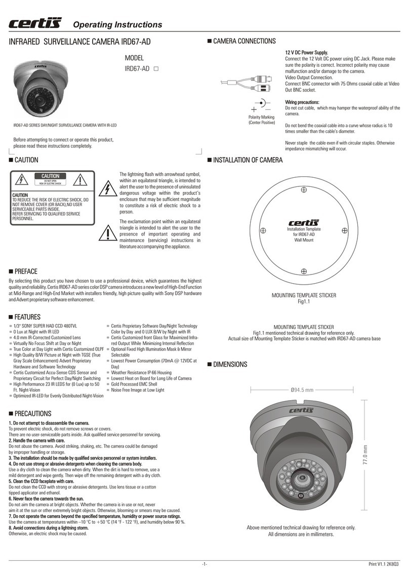
Certis VFD4803-AD User manual

Print V1.1 2K8Q3
DIP SWITCHES MAJOR OPERATING CONTROLS AND THEIR FUNCTIONSDIP SWITCHES MAJOR OPERATING CONTROLS AND THEIR FUNCTIONS
IRIS AND FIELD OF DEPTH
When adjusting focus, an important aspect is depth of field,
actually the depth of focus. The term depth is used because
we can describe it as being deep or shallow. If the in-focus
area goes well into (long distance) the subject field is referred
to as being deep. If the background area is not in focus but the
subject field is in sharp focus, the field is referred to as being
shallow.
The depth of field will change depends on the focal length of
the lens, the iris of the lens and the shooting distance. And in
surveillance cameras, the lens iris has an effect on focusing.
As the diagram makes clear, the wider the lens iris opening
size, the shallower will be the depth of field.
TECH TIPS FOR FOCUS AND DEPTH OF FIELDTECH TIPS FOR FOCUS AND DEPTH OF FIELD
Depth of fie ld is deep
Depth of field is shallo w
TECH TIPS ON FOCUS
Why will correct focus set during the day going off at night?
That’s because focus has not been precisely set. Shooting with an auto-iris lens, the amount of light during
the day makes the lens iris opening stay small. This results in a deep depth of field. But as day turns to night,
the lens iris opens to get more light, the depth of field is reduced and the focus goes off. When using auto-
iris lens, the ND filter must be used to approximate nighttime light conditions so that the lens iris stays open
and depth of field is reduced before adjusting the focus.
Neutral Density (ND) Filter: A filter which reduces light coming through the camera lens without any effect
on the light’s color temperature.
Certis VFD 03-AD with Two Potentiometer control of auto-iris lens do not require an ND filter for adjusting
focus. To achieve perfect focus simply and easily, just turn LEVEL potentiometer counter clock wise, the
lens iris open and shallow depth of field is maintained. Now adjust focus and then set LEVEL potentiometer
as required to light conditions.
TECH TIPS ON FOCUS
INSTALLATION OF CAMERAINSTALLATION OF CAMERA
Note
Do not touch any component like the PCB and the lens, as this will damage the camera.
Adjust the camera angle.
Camera angle can be adjusted for up to 180º(± 65º) for horizontal rotation, for up to 90º (± 70º) for
vertical rotation.
Switch on the power supply of 12 V DC after completing camera Connections. The power is supplied to
the camera, Connect the monitor to the Video Output terminal to permit a picture to be viewed on the
monitor.
Set the Shutter
Shutter Fixed switch-4 to ON if light flicker is annoying. Light flicker may interfere with the view under
fluorescent lamps in the area where power frequency is 50 Hz. In such cases, set the Shutter Fixed
switch to "ON" position, and the image free from flickering can be obtained.
Note
If the Shutter Fixed switch-4 is set to the ON position, sensitivity is reduced compared to operation in
the OFF position. When using the camera in a dark location, or where light flicker is not an annoyance,
set the switch to the OFF position.
Adjust the angle of view with the Zoom ring and adjust the focus with the Focus ring for the best
possible picture reproduction. After lens adjustment completion, tighten both the Zoom ring fixing
screw and the Focus ring fixing screw.
Note
Do not touch any component like the PCB and the lens, as this will damage the camera.
Note
Since the Iris control (for sensitivity adjustment) is factory-preset to an optimum position for general
use, avoid tampering with it in normal conditions. Turning the control unnecessarily could cause
reduced picture quality or equipment failure. When the Iris control needs to be readjusted to match a
specific subject, adjust LENS IRIS LEVEL potentiometer to an optimum level. After adjustment, place a
lens cap over the lens for several seconds and then release to check the lens for correct iris operation.
If the focus is adjusted for a subject under good lighting conditions, the subject may go out of focus
when conditions become dark. To avoid this, adjust the lens focus after setting total open of lens iris.
(For total open lens iris move iris LEVEL Control Potentiometer counter clock wise position till
end.).Please refer to TECH TIPS FOR FOCUS AND DEPTH OF FIELD.
Note
LENS IRIS LEVEL LENS IRIS LEVEL
-1-
VFD4803-AD
MODELMODEL
VARI-FOCAL DOME SURVEILLANCE CAMERA
VFD4803-AD
VARI-FOCAL DOME SURVEILLANCE CAMERA
VFD4803-AD
Before attempting to connect or operate this product,
please read these instructions completely.
VFD4803-AD PROFESSIONAL SERIES VARI-FOCAL DOME CAMERA
!
DO NOT OPEN
RISK OF ELECTRIC SHOCK
CAUTION
TO REDUCE THE RISK OF ELECTRIC SHOCK, DO
NOT REMOVE COVER (OR BACK),NO USER
SERVICEABLE PARTS INSIDE.
REFER SERVICING TO QUALIFIED SERVICE
PERSONNEL.
CAUTION
CAUTIONCAUTION !
CAUTIONCAUTION
The lightning flash with arrowhead Symbol,
within an equilateral triangle, is Intended to
alert the user to the presence of uninsulated
dangerous voltage within the product’s
enclosure that may be sufficient magnitude
to constitute a risk of electric shock to a
person.
The exclamation point within an equilateral
triangle is intended to alert the user to the
presence of important operating and
maintenance (servicing) instructions in
literature accompanying the appliance.
PREFACEPREFACE
By selecting this product you have chosen to use a professional device, which guarantees the highest
quality and reliability. Certis VFD03-AD series color DSP camera introduces a new level of High-End
Function at Mid-Range and High-End Market with installers friendly, high picture quality and high resolution
through hardware and software enhancement.
FEATURESFEATURES
Sony 1/3” Format Super HAD CCD Sensor
480 TVL Resolution
2.9 to 10.0 mm Vari-Focal Auto-Iris Japanese Lens
8 DIP Switches for Professional Installation Setup
Wide In-put Voltage Range (DC7.5V to DC18V)
Power Consumption(DC12V / 90 mA)
Super Sensitive Low Lux Image Capture
Ultra Clear Image Performance
6 Types White Balance Setup with (DIP1,2,3*)
Shut.-Fixed (Fl-Free)1/100 or 1/120 with (DIP4*)
AGC High/Low Setup with (DIP5*)
Back Light Compensation On/Off with (DIP6*)
Electronic Auto Iris/Manual Iris with (DIP7*)
Auto Exposure/8 Types Fixed with (DIP8*)
Noise Free Image at Low Light
Optically Corrected Top Dome Cover
Compact and Light Weight
PRECAUTIONSPRECAUTIONS
1. Do not attempt to disassemble the camera.
To prevent electric shock, do not remove screws or covers.
There are no user-serviceable parts inside. Ask qualified service personnel for servicing.
2. Handle the camera with care.
Do not abuse the camera. Avoid striking, shaking, etc. The camera could be damaged
by improper handling or storage.
3. The installation should be made by qualified service personnel or system installers.
4. Do not use strong or abrasive detergents when cleaning the camera body.
Use a dry cloth to clean the camera when dirty. When the dirt is hard to remove, use a
mild detergent and wipe gently. Then wipe off the remaining detergent with a dry cloth.
5. Clean the CCD faceplate with care.
Do not clean the CCD with strong or abrasive detergents. Use lens tissue or a cotton
tipped applicator and ethanol.
6. Never face the camera towards the sun.
Do not aim the camera at bright objects. Whether the camera is in use or not, never
aim it at the sun or other extremely bright objects. Otherwise, blooming or smears may be caused.
7. Do not operate the camera beyond the specified temperature, humidity or power source ratings.
Use the camera at temperatures within –10 °C to +50 °C (14 °F - 122 °F), and humidity below 90 %.
8. Avoid connections during a lightning storm.
Otherwise, an electric shock may be caused.
1. Do not attempt to disassemble the camera.
2. Handle the camera with care.
3. The installation should be made by qualified service personnel or system installers.
4. Do not use strong or abrasive detergents when cleaning the camera body.
5. Clean the CCD faceplate with care.
6. Never face the camera towards the sun.
7. Do not operate the camera beyond the specified temperature, humidity or power source ratings.
8. Avoid connections during a lightning storm.
INSTALLATION OF CAMERAINSTALLATION OF CAMERA
CAMERA CONNECTIONSCAMERA CONNECTIONS
12 V DC Power Supply.
Connect the 12 Volt DC power using DC Jack. Please make
sure the polarity is correct. Incorrect polarity may cause
malfunction and/or damage to the camera.
Video Output Connection.
Connect BNC connector with 75 Ohms coaxial cable at Video
Out BNC socket.
Wiring precautions:
Do not bend the coaxial cable into a curve whose radius is 10 times smaller
than the cable’s diameter.
Never staple the cable even if with circular staples. Otherwise impedance
mismatching will occur.
12 V DC Power Supply.
Video Output Connection.
Wiring precautions:
Do not bend the coaxial cable into a curve whose radius is 10 times smaller
than the cable’s diameter.
Never staple the cable even if with circular staples. Otherwise impedance
mismatching will occur.
CAMERA CONNECTIONSCAMERA CONNECTIONS
This Certis operating control guide is only intended for use by installers who have an adequate working
knowledge of video system! This guide outlines the most important information about camera. It is,
however, vital that you should also refer to the full Application Guide of Certis.
Functionality Specifications: As of Certis Technologies update knowledge, Certis with 32X32 mm size have
layout with Lowest Power Consumption & all possible external control function from Sony SS-11X solution.
Professional types Certis have different software and hardware built on board, supplied with 8 DIP
switches mounted on the top board to set function as below;
Setting White Balance: With different on-off combinations of switches 1, 2 & 3, user can set ATW-
Auto Trace White Balance, Indoor WB (Approx.3200K.), Fluorescent Light WB (4200K.), Fixed WB
(Approx. 4700K.), Out Door WB (Approx.6300K.) and Push to Hold WB.
ATW Mode: Auto Trace White Balance Mode. ATW is a feedback system
that automatically aligns the white balance by detecting the R, G and B
before gamma correction processing on DSP. To set ATW Mode, turn off
switches 1, 2, 3.
ATW Mode:
ONON
11334455667788
22
Push Mode: Turn on switch 2 and turn off switches 1,3. During Push
Mode operation is performed at a faster operating speed than ATW
without an operation frame or other limitations. However, the
response time, operation frame and other factors cannot be selected.
Indoor Fixed Mode: Turn on switch 3 and turn off switches 1 and 2.
Color temperature will be set at approximately 3200K .
Fluorescent Light Fixed Mode: Turn on switches 1,3 and turn off
switch 2. Color temperature will be set at approximately 4200K .
Manufacturer Default Fixed Mode: Turn on switches 2,3 and turn off
switch 1.Color temperature will be set at approximately 4700K .
Outdoor Fixed Mode: Turn on switches 1,2 and 3. Color temperature
will be set at approximately 6300K .
Push Mode:
Indoor Fixed Mode:
Fluorescent Light Fixed Mode:
Manufacturer Default Fixed Mode:
Outdoor Fixed Mode:
ONON
11334455667788
22
ONON
11334455667788
22
ONON
11334455667788
22
ONON
11334455667788
22
ONON
11334455667788
22
Hold Mode: Useful for locking white balance by using white reference
at available light conditions.
Step-1 First turn on switch 2, face camera towards white paper for 3
to 5 seconds, Step-2 turn on switch 1. After this two steps, operation
stops ATW and mode shifts to White Balance lock mode, and RED and
BLUE gain at that point written to the EEPROM of camera. To perform
the same White Balance after next power restoration, keep switches
1 & 2 at ON .
Shutter Fixed Mode: Turn on switch 4, the shutter speed will be fixed
at 1/100(s)- NTSC and 1/120(s)- PAL to reduce the flicker of
fluorescent lights. In fixed shutter mode, AE operation is performed
only by AGC control.
AGC Max/Min: Turn on switch 5 to set Minimum AGC gain,turn off
switch 5 to set Maximum AGC gain.
BLC On/Off: Turn on switch 6 to set Back Light Compensation ON, turn
off switch 6 to stop Back Light Compensation.
Hold Mode:
Shutter Fixed Mode
AGC Max/Min:
BLC On/Off:
Step-1
Step-2
ONON
11334455667788
22
ONON
11334455667788
22
ONON
11334455667788
22
ONON
11334455667788
22
ONON
11334455667788
22
MOUNTING TEMPLATE STICKER
Above mentioned technical drawing for reference only.
Actual size of Mounting Template Sticker is matched with Dome Base
1. Stick Mounting Template Sticker supplied for drill mark the mounting hole locations on the mounting
surface. The unit is intended to be mounted with four #10 screws or four M5 screws (not supplied)
through the four outer holes at the base of Dome Camera.
2. Install the appropriate anchors or threaded fasteners.
Operating Instructions
Installation Template
For VFD 03-AD Vari-Focal
Dome Camera
www.certissecurity.com
Ceiling
180º
90º
Polarity Marking
(Center Positive)

TECHNICAL SPECIFICATIONS TECHNICAL SPECIFICATIONS
DIP SWITCHES MAJOR OPERATING CONTROLS AND THEIR FUNCTIONSDIP SWITCHES MAJOR OPERATING CONTROLS AND THEIR FUNCTIONS
Print V1.1 2K8Q3-2-
MIRIS On/Off: Turn on switch 7 to set Manual Iris mode. This switch turns
on for best performance of Mechanical Iris type lens. In this mode, the
shutter speed is fixed at 1/60 (s)-NTSC and 1/50 (s)-PAL. Auto Exposure
operation is performed by AGC control and by mechanical iris inside of the
external lens.
AE/ME On/Off: This switch selects the mode of exposure between Auto
Exposure & Manual Exposure. In ME (Manual Exposure) mode, the various
shutter speed can be set by SHTFIX (SW-4), BLC (SW-6) and MIRIS (SW-
7). Turn on switch 8 to perform Manual Exposure. Refer to the following
table 1.0 for various speed of exposure during ME mode.
MIRIS On/Off:
AE/ME On/Off:
ONON
11334455667788
22
ONON
11334455667788
22
ONON
11334455667788
22
ONON
11334455667788
22
ONON
11334455667788
22
ONON
11334455667788
22
ONON
11334455667788
22
ONON
11334455667788
22
ONON
11334455667788
22
ONON
11334455667788
22
ME (Manual Exposure) Mode Shutter Speed ME (Manual Exposure) Mode Shutter Speed
SWITCH-8SWITCH-8
ON
ON
ON
ON
ON
ON
ON
ON
ON
ON
ON
ON
OFF
OFF
OFF
OFF
SWITCH-4SWITCH-4
OFF
OFF
OFF
OFF
ON
ON
ON
ON
SWITCH-6SWITCH-6
OFF
OFF
OFF
OFF
ON
ON
ON
ON
SWITCH-7SWITCH-7
1/60
1/100
1/250
1/500
1/1,000
1/2,000
1/4,000
1/10,000
Shutter Speed
(NTSC) [s]
Shutter Speed
(NTSC) [s]
1/50
1/120
1/250
1/500
1/1,000
1/2,000
1/4,000
1/10,000
Shutter Speed
(PAL) [s]
Shutter Speed
(PAL) [s]
[Table 1.0]
VFD4803-AD
NTSC/PAL
Signal systemSignal system
Scanning systemScanning system
Scanning frequency(H)Scanning frequency(H)
Scanning frequency(V)Scanning frequency(V)
Sync. systemSync. system
Image sensorImage sensor
Total effective pixelsTotal effective pixels
S/N ratioS/N ratio
GammaGamma
Resolution Resolution
Focus modeFocus mode
Min. illuminationMin. illumination
Lens typeLens type
MODELMODEL
Video output levelVideo output level
White BalanceWhite Balance
Shutter FixedShutter Fixed
AGCAGC
Exposure (AE/ME)Exposure (AE/ME)
Current consumptionCurrent consumption
Supplied voltageSupplied voltage
Weight Weight
MirrorMirror
DimensionsDimensions
Iris Iris
I / O connectorI / O connector
BLCBLC
2:1 Interlace
15734 Hz / 15625 Hz
59.94Hz / 50.00Hz
Sony Super HAD 1/3 inch
Internal
525 lines / 625 lines
380K / 440K
Standard 2.9 mm to 10 mm F(1.2) Vari-Focal Auto-Iris Japanese Lens
More than 48 dB ( AGC OFF )
0.45
480 Lines
1.0 Vp-p ( 75 Ohms, composite )
Manual
0.3 LUX.(F1.2)
User Selectable with DIP Switches 1,2 & 3 Combinations.
(ATW, PUSH, WB-Lock, Indoor, Outdoor, Fl. Light, Mfr. Default)
User Selectable Shutter Fixed Mode to 1/120(PAL)
& 1/100(NTSC) with DIP Switch 4
User Selectable AGC Mode High & Low with DIP Switch 5 On/Off
User Selectable Back Light Compensation Mode On & Off with DIP Switch 6 On/Off
DC Auto Iris Lens with DIP Switch 7 On
User Selectable Exposure Mode Auto Exposure & Manual Exposure with DIP Switch 8 On/Off
& Manual 8 Types Fixed Shutter Speed with DIP Switches 4,6 & 7 Combination .
Optional on OEM request
DC 7.5 V -18 V ( Recommendation DC 12 0.5 V )±
90 mA @ 12 VDC
Video output : BNC Connector and 12 V DC Input : DC Socket
113.0 mm (Base Diameter) X 86.5 mm (H)
Approx. 190.0 grams
Operating Instructions
Above mentioned technical drawing for reference only. All dimensions are in millimeters and approximate.
PACKAGE CONTENTS PACKAGE CONTENTS
1. CCD CAMERA
2. OPERATING INSTRUCTIONS (MANUAL)
3. MOUNTING TEMPLATE STICKER
1PC.
1PC.
1PC.
TECHNICAL TIPSTECHNICAL TIPS
If you have a choice of crimping connectors, look for the ones that are likely to last longer
in respect to physical use and corrosion, like silver plated or gold plated BNCs. A good practice would
use “Rubber sleeves” (sometimes called “protective sleeves” ) for further protection of the interior of
the BNC from corrosion and to minimize bending stress by plugging and unplugging.
Rubber protector
Crimping
BNC ring
Crimping
center piece BNC shell
Suggestions for correct termination
( dimensions depend on stripping tool )
PROPER BNC TERMINATION
NOTESNOTES
BE AWARE THAT CONDITIONS CHANGE.
All the components of your CCTV system are designed to specific International standards, and are
interdependent on each other for proper operation. Things that affect one component may affect the
performance of an entire CCTV system over time. During wet weather, for instance, your system may be
much more prone to ground loops, which can play havoc with the quality of the video. Simple things like
cables and connectors can deteriorate as they get older. Cables and connectors are often overlooked, and
yet as their age, are capable of causing problems for the entire system. If in doubt, call the installing
company for an inspection.
BE AWARE THAT CONDITIONS CHANGE.
The coaxial cable is the most common medium for transmission of video signals and
sometimes video and PTZ data together. It is also known as unbalanced transmission, which comes from
the concept of the coaxial cable ( sometimes called “coax” for short ).A cross section of a coax is shown
above. It is a symmetrical and coaxial construction.
The video signal travels through the center core, while the shield is used to common the
ground potential of the end devices - the camera and the monitor, for example It not only commons the
ground potential, but also serves to protect the center core from external and unwanted electromagnetic
interference ( EMI ). The idea behind the coaxial concept is to have all the unwanted EMI induced in the
shield only. When this is properly grounded, it will discharge the induced noise through the grounds at the
camera and monitor ends. Electrically, the coaxial cable closes the circuit between the source and the
receiver, where the coax core is the signal wire, while the shield is the grounding one. That is why it is called
an unbalanced transmission.
COAXIAL CABLE
Protective plastic
Copper shield
Di electric
Center conductor
Cross section of a coaxial cable
CARE AND FEED YOUR CCTV INSTALLATION CARE AND FEED YOUR CCTV INSTALLATION
Congratulations on the installation of your new Closed Circuit Television (CCTV) Security
System. It has been installed, tested, and is up and running. What now? What steps do you take to get
the best performance and results from your investment? Does it require any maintenance? How will
you know there is a problem before it's too late and important information has been lost forever? Here
are some tips and guidelines to keep your system operating at peak performance:
CCTV IS NOT LIKE YOUR HOME TV SET.
Besides no commercials, this means many things. For one, it is designed for continuous long-term use. The
components are built to completely different standards.
As an example, commercial broadcast video (TV) uses cameras that cost thousands of dollars, and are not
practical for security use. There are a great variety of cameras for the security market, with many different
uses and features. Most are of high quality and will provide good performance. But they are often installed
in locations that can make them susceptible to outside forces; even simple things like cleaning the lenses
occasionally may be necessary, particularly if they are installed outdoors. The monitor operates differently
from your TV too. It does not receive radio broadcasts, but rather gets its signal directly through a cable
(coax or S-Video, not ESPN or HBO). A normal television can be used as a security monitor, but will usually
have to be replaced 2 or 3 times in the life of one security monitor.
CCTV IS NOT LIKE YOUR HOME TV SET.
(Certis may, at any time and without notice, make changes or improvements to the products and
services offered and/or cease producing or commercializing them.)
The Certis trademark are properties of Security Pte. Ltd. - Singapore.
DIMENSIONSDIMENSIONS
Ø113.0 mm
86.5 mm
Other Certis Security Camera manuals
