cetoni neMESYS User manual

NEMESYS
Hardware Manual and Reference
ORIGINAL INSTRUCTIONS 2.08–AUGUST 2018

2neMESYS Hardware Manual
CETONI GmbH
Wiesenring 6
07554 Korbussen
Germany
T+49 (0) 36602 338-0
F+49 (0) 36602 338-11
www.cetoni.de

neMESYS Hardware Manual 3
The information and data contained in this document are subject to change without notice. CETONI
GmbH is constantly striving to develop all its products. This means that there may be changes in form,
equipment and technology. Claims cannot therefore be made on the basis of information, illustration or
descriptions in these instructions. The description for the product specification in this manual does not
constitute an integral part of the contract.
If you control the products with a software from CETONI GmbH, you agree to the applicable license
agreement, which can be read in the corresponding software manual. This and all other current product
manuals can be found at https://www.cetoni.de/en/downloads/manuals.
The reproduction, distribution and utilization of this document as well as the communication of its
contents to others without explicit authorization are prohibited. Offenders will be held liable for the
payment of damages.
We are always open to comments, corrections and requests. Please send them to info@cetoni.de.
The general terms and conditions of CETONI GmbH shall apply. Alternative agreements must be in
written form.
Copyright © CETONI GmbH –Automation and Microsystems. All rights reserved.

4neMESYS Hardware Manual
1Overviews and Directories
1.1 Table of Contents
1Overviews and Directories 4
1.1 Table of Contents 4
1.2 Revision History 7
2Introduction 8
2.1 Foreword 8
2.2 Symbols and Key Words Used 8
2.3 Norms and Guide Lines 9
2.4 Application Purpose 9
2.4.1 General Description of the Advice 9
2.4.2 Intended Use 9
2.4.3 Reasonably Foreseeable Faulty Application 9
2.4.4 Safety Advice 10
2.4.5 Measures for Safe Operation 11
2.4.6 Safety Devices on the System 11
2.4.7 Condition of the Devices 11
2.5 Warranty and Liability 12
2.6 Scope of Supply 13
3Initial Start-Up 14
3.1 Software Installation 14
3.2 System Configuration 14
3.2.1 Connecting the Base Module 15
3.2.2 Connecting Additional Modules 16
3.3 Module Configuration 18
4Base Module BASE 120 19

neMESYS Hardware Manual 5
4.1 Technical Data 19
4.1.1 Environment 19
4.1.2 Mechanical Data 19
4.1.3 Electrical Data 20
4.1.4 Interfaces 20
4.2 Transport and Storage 20
4.3 Maintenance and Care 20
4.4 Hardware Operation 21
5Low Pressure Syringe Pump 22
5.1 Technical Data 22
5.1.1 Environment 22
5.1.2 Mechanical Data 22
5.1.3 Electrical Data 23
5.1.4 Interfaces 23
5.1.5 Dosing Performance 23
5.1.6 Valve 24
5.2 Transport and Storage 24
5.3 Maintenance and Care 25
5.4 Hardware Operation 25
5.4.1 Mounting a Syringe 26
5.4.2 Fluidic/Valve 29
6Mid Pressure Syringe Pump 32
6.1 Technical Data 32
6.1.1 Environment 32
6.1.2 Mechanical Data 32
6.1.3 Electrical Data 33
6.1.4 Interfaces 33
6.1.5 Dosing Performance 34
6.2 Transport and Storage 35
6.3 Maintenance and Care 35

6neMESYS Hardware Manual
6.4 Hardware Operation 35
6.4.1 Mounting a Syringe 36
6.4.2 Fluidic/Valve 39
6.4.3 Mounting the Blank Holder 41
7High Pressure Syringe Pump 42
7.1 Technical Data 42
7.1.1 Environment 42
7.1.2 Wetted Parts 42
7.1.3 Mechanical Data 43
7.1.4 Electrical Data 43
7.1.5 Interfaces 43
7.1.6 Dosing Performance 44
7.2 Transport and Storage 45
7.3 Maintenance and Care 45
7.4 Hardware Operation 45
7.4.1 Mounting the Safety Hood 46
7.4.2 Fluidic Connections 47
7.4.3 Mounting a Syringe 49
7.4.4 Pressure Sensor 51
8Accessory Port 53
9RS232 Connection 55
9.1 Pin Assignment of Module Interfaces 55
9.2 OEM RS232 Cable Set 55
9.2.1 RS232 Wiring 55
9.2.2 Communication Settings 56
9.2.3 Pin Assignment of the RS232 Cable 56
10 Disposal 57

neMESYS Hardware Manual 7
1.2 Revision History
REV
DATE
CHANGE
2.00
21.06.2013
Manuals merged
2.01
06.02.2014
Adaption of the pin assignment table
2.02
29.01.2015
Correction of pin assignment table
2.03
07.09.2015
Removed cable colors for I/O interface
Added safety advices about the Pressure Equipment Directive
2.04
19.10.2015
Correction of the pin assignment of the I/O-Interface for the High Pressure Syringe Pump
2.05
10.03.2016
New Corporate Design
2.06
21.11.2016
Correction of pin assignment table
2.07
29.05.2017
Pictures BASE module and USB cable updated
2.08
06.08.2018
Pressure sensor type in High Pressure Syringe Pump changed

8neMESYS Hardware Manual
2Introduction
2.1 Foreword
Thank you for deciding to purchase a CETONI product. We would like to support you with this
handbook as far as possible in your interaction with the neMESYS syringe pump system. We are directly
available for any questions or suggestions that you may have.
The neMESYS syringe pump system may only be taken in operation after carefully reading and
understanding this manual. We wish you much success in your work with the neMESYS syringe pump
system.
2.2 Symbols and Key Words Used
The following symbols are used in this manual and are designed to aid your navigation through this
document:
HINT. Describes practical tips and useful information to facilitate the handling of the
software.
IMPORTANT. Signifies important hints and other useful information that may not
result in potentially dangerous or harmful situations.
ATTENTION. Identifies a potentially harmful situation. Failure to avert this situation
may result in damage to the product or anything in its proximity.
CAUTION. Indicates a potentially dangerous situation. Failure to avert this situation
may result in light or minor injuries or property damage.

neMESYS Hardware Manual 9
2.3 Norms and Guide Lines
CETONI GmbH declares under its sole responsibility, that the individual neMESYS devices
and the entire neMESYS syringe pump system comply with the health and safety
requirements of the relevant European directives.
2.4 Application Purpose
2.4.1 General Description of the Advice
The neMESYS devices are syringe pumps. They allow emptying and filling syringes by the relative linear
movement of a syringe- and a piston holder.
2.4.2 Intended Use
The neMESYS syringe pump system serves for precise and pulsation-free dosing of fluids in the range of
nanolitres per second up to millilitres per second. Pressures of up to several hundred bar can be reached
depending on the device.
Application usually takes place in laboratory-like rooms.
2.4.3 Reasonably Foreseeable Faulty Application
A use for applications distinct from the intended purpose can lead to dangerous situations and is to be
omitted.
CAUTION. The unit must not be used as a medical device or for medical purposes.

10 neMESYS Hardware Manual
2.4.4 Safety Advice
The safety of the user and a failure-free operation of the devices are assured only if original parts are
used. Only original accessories may be used. Warranty claims will not be accepted for damage due to
the use of alien accessories or expendables.
The devices have been developed and constructed in such a way as to largely rule out hazards due to its
intended use. Nevertheless, you must observe the following security measures in order to exclude any
remaining hazards:
CETONI GmbH points out the responsibilities of the operator for the operation of the devices.
The laws and regulations of the place of installation must be observed while operating the
devices! To ensure a safe work routine, operators and users must assume responsibility for
adhering to regulations.
The devices must not be used as a medical device or for medical purposes.
Before operating the unit, the user must at all times ensure the operational reliability and the
adequate and orderly condition of the unit.
The user must be familiar with the operation of the devices and the software.
The devices and pipes must be checked for damage before operation. Damaged pipes and plug
devices must be replaced immediately.
Cables must be laid in a way that avoids any risk of stumbling.
Any moving parts must not be touched whilst the devices are in operation. There is a risk of
crushing!
It is not allowed to use the devices in an explosive atmosphere or with potentially explosive
substances.
The device is designed and approved to work in fluidic systems, which fall within the scope of
Article 4 Paragraph 3 of the Pressure Equipment Directive 2014/68/EU. This means that the
system may not exceed a maximum volume of 1 liter. With the use of fluids from Group 1
according to Article 13 of the Pressure Equipment Directive 2014/68/EU, the maximum
allowable system pressure is 200 bar. For fluids from Group 2 it is 1000 bar. If different,
product-specific values for the maximum pressure are given in the section "Technical Data",
these values must be complied with. Regarding the maximum operating temperature, the
specification from the section "Technical Data" must be observed.
CETONI GmbH is not liable for consequences that may arise if the user expands the system by
peripheral devices, such that one of the values or both values are exceeded.

neMESYS Hardware Manual 11
It is the user's responsibility to become familiar with the mentioned Pressure Equipment
Directive and to comply with the prevailing requirements.
Wear protective glasses if you are working with corrosive, hot or otherwise dangerous
substances during assembly work on the device.
Transportation, storage or operation of the devices below 0°C with water in the fluid passages
may cause damage to the modules.
2.4.5 Measures for Safe Operation
2.4.5.1 ELECTROMAGNETIC EMISSIONS
The Qmix system is intended for use in any type of facility, connected directly to the public power
supply network that supplies buildings used for domestic purposes.
2.4.5.2 ELECTROSTATIC DISCHARGE
Floors should be made of wood, concrete, or ceramic tiles. If the flooring is made of a synthetic material;
the relative humidity must be at least 30%.
2.4.5.3 ELECTRIC DISTURBANCES
The quality of the supply voltage should be to the standard of a typical business or hospital
environment.
2.4.5.4 MAGNETIC DISTURBANCES
Do not place power connector cables, even of other appliances, in close proximity of the devices and
their cables. Mobile communication devices may not be used in closer proximity of the devices or their
cables than the recommended safety distance!
2.4.6 Safety Devices on the System
The system can be switched off at any time in an emergency using the mains switch on the Base
Module (rocker switch on the side of the housing); this will cause no damage to the unit.
2.4.7 Condition of the Devices
Irrespective of the faultless manufacture of the devices, damage can occur whilst the unit is in
operation. With this in mind, always carry out a visual check of the components mentioned before use.
Pay particular attention to crushed cables, damaged tubing, and deformed plugs. If you should notice
any damage, please do not use the devices and inform CETONI GmbH without delay. CETONI will put

12 neMESYS Hardware Manual
your devices back to an operational condition at the earliest. Do not attempt to repair the devices
yourself.
2.5 Warranty and Liability
The devices left our company in perfect condition. Only the manufacturer is permitted to open the
devices. All guarantee and liability entitlements, particularly damage entitlements due to personal
injuries, are void if the devices are opened by an unauthorized person.
The duration of the warranty is 1 year from the day of delivery. It is not extended or renewed due to
work carried out under warranty.
CETONI GmbH considers itself responsible for the devices with regard to safety, reliability and function
only if assembly, new settings, changes, extensions and repairs are carried out by CETONI GmbH or an
authorized centre, and if the devices have been used in accordance with the instruction manual.
The neMESYS syringe pump system conforms to the basic safety regulation standards. Industrial
property rights are reserved on the circuits, methods, names, software programs, and units.

neMESYS Hardware Manual 13
2.6 Scope of Supply
The delivery should correspond to the order. The following items should be included in the scope of
supply of the base module:
COUNTRY SPECIFIC POWER CABLE FOR NON-
HEATING APPARATUS
USB CABLE 10 m ACTIVE
BUS TERMINATING PLUG
HARDWARE-MANUAL AND CD WITH SOFTWARE-
MANUAL, SOFTWARE AND DRIVERS
14 neMESYS Hardware Manual
3Initial Start-Up
IMPORTANT. Please carefully read this manual and the associated software manual in
their entirety before starting up your neMESYS syringe pump system.
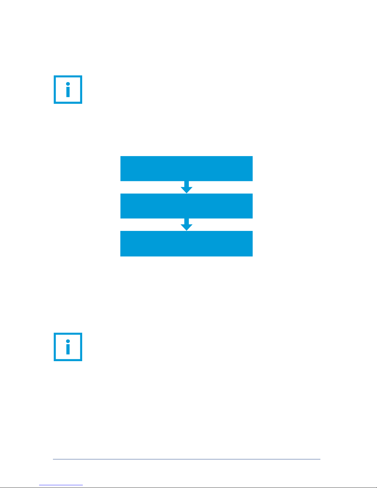
To ensure failure-free initial start-up of your syringe pump system, the following sequence must be
adhered to. The individual steps are described in more detail in the sections below.
3.1 Software Installation
Before connecting the system, the supplied software and drivers must be installed. The procedure is
described in the associated software manual, which you can find on the supplied CD or USB stick.
IMPORTANT. Install the software and device drivers as described in the software
manual, before connecting your device to a PC via USB.
3.2 System Configuration
Place your neMESYS modules on a firm and level surface in the desired sequence, without connecting
them. You can arrange the system horizontally or vertically.
Module Configuration
Setting syringe size, pressure limits…
System Configuration
Adding modules to the system one by one
Software Installation
Before initially connecting the devices to a PC
neMESYS Hardware Manual 15
ATTENTION. In vertical arrangement the assembly will be less stable. Please take
precautions to avoid tipping and place the devices at least 40 cm from the edge of the
table.
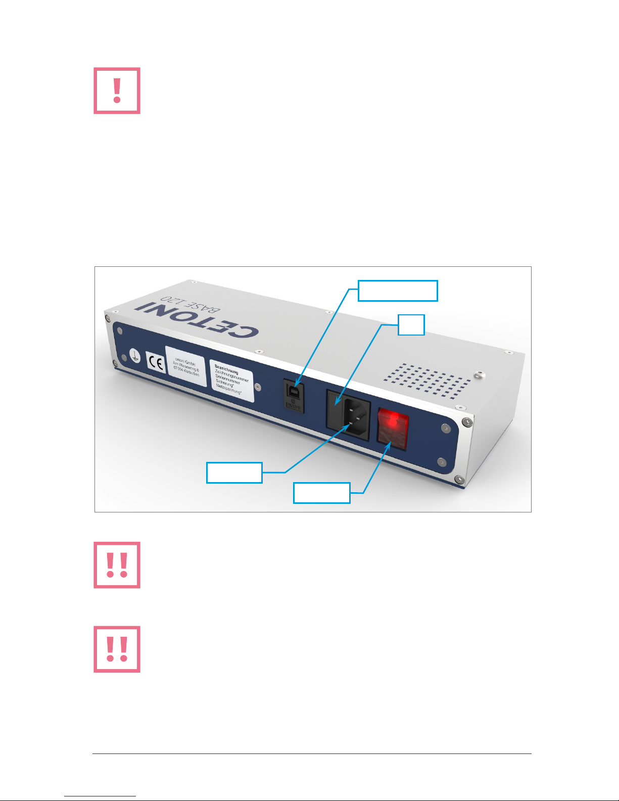
3.2.1 Connecting the Base Module
After installing the software and device driver, connect the USB connector of the base module (USB
type B) with a free USB connector on your PC (USB type A). Plug the base module into a power outlet
using the supplied power cable. The device can be connected to AC power sources ranging from 90 to
264 volts and 47 to 63 Hz.
CAUTION. Danger of injury due to damaged power lines and plugs! Check the device
and power lines for damage! Never operate the device with damaged power lines or
plugs! Only use supplied cables.
CAUTION. Danger of stumbling due to connecting cables! Place cables in such way as
to avoid any danger of stumbling!
USB-socket (type B)
Power socket
Fuse
Power switch
16 neMESYS Hardware Manual
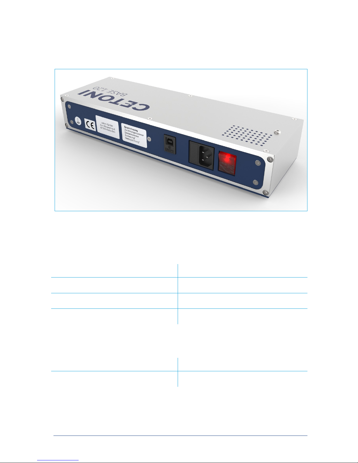
Flip the power switch to turn on the device. The on/off switch should light up while the device is turned
on. If this is not the case, make sure that the power cord is firmly connected to the device and the
power outlet.
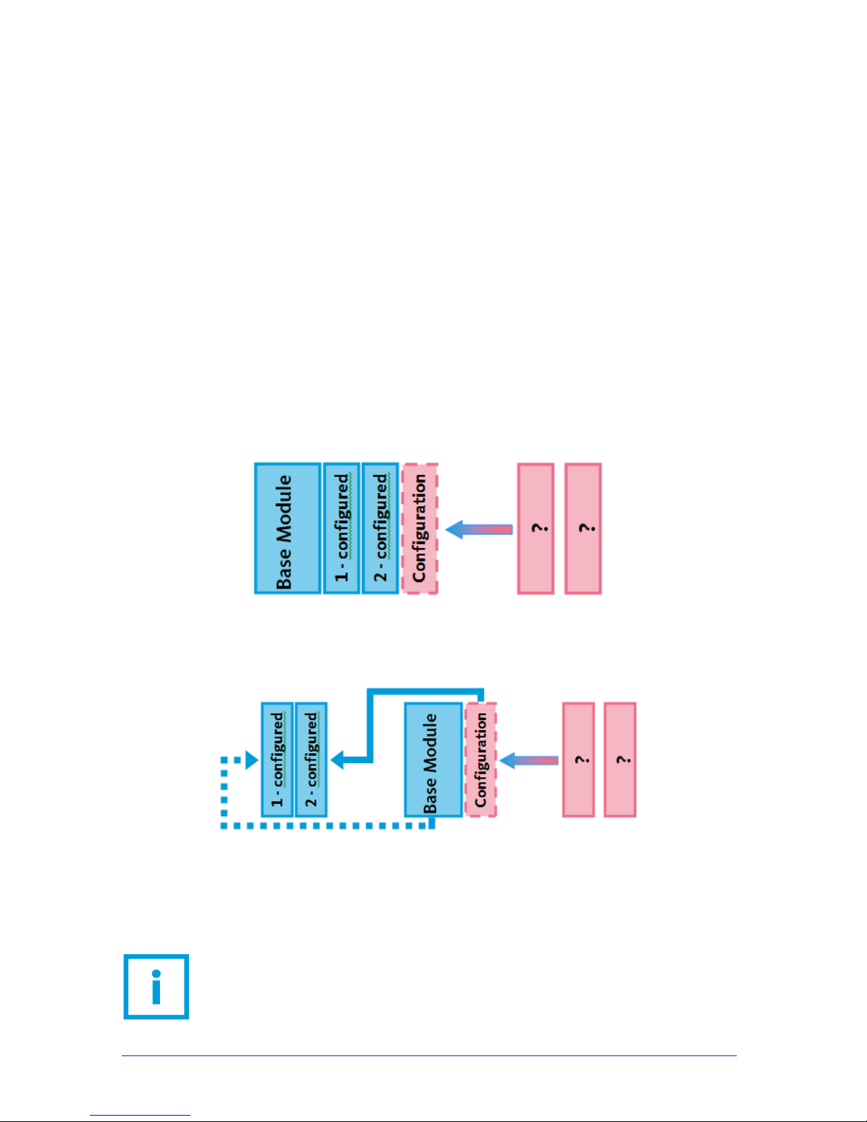
3.2.2 Connecting Additional Modules
The modules must be configured individually by the software before they can be used. The procedure is
slightly different depending on whether you use the neMESYS UserInterface or QmixElements.
The exact process is described in the respective software manuals and will be touched on briefly here:
In case of the neMESYS UserInterface the modules are added to the base module one by one,
before being configured. According to this sequence, each module is assigned a number internally.
That is the reason devices have to be reset through “Remove Dosing Unit” before they can be used
in a different system. This also resets the assigned number.
In QmixElements every module is plugged into the base module, configured and unplugged
individually. Once all modules are configured, the system can be assembled.
Following, we will describe the mechanical connection of additional modules. To ensure correct function
of the overall system, please read and observe the respective section in the associated software manual,
before connecting additional modules.
IMPORTANT. Please read and observe the respective section of the associated
software manual before connecting additional devices.

neMESYS Hardware Manual 17
Place the module you would like to connect next to your base module or your existing system in such
way that the centering pins of the final system module face the centering holes of the module to be
connected.
Plug the new module into the system. The centering pins are inserted into the respective centering
holes and the plug connectors are connected. To ensure clean contact between the modules, both
modules must make physical contact across their entire surface. Avoid canting the modules.
Connecting additional modules
Insert the bus termination plug into the last connected module of your system. Make sure that this plug
is always plugged in before the system is turned on. Otherwise, there may be disruptions in data
communication.
IMPORTANT. Always insert the bus termination plug into the socket of the final
connected system. Otherwise there may be disruptions in data communication.

18 neMESYS Hardware Manual
Connecting Terminator Plug
IMPORTANT. Deactivate the standby/sleep mode of your PC to avoid malfunctions.
3.3 Module Configuration
Among other things, module configuration includes inserting syringes, using valves and connecting
periphery devices. All necessary information with respect to technical data and hardware operation as
well as configuration of the various models can be found in the following module-specific sections of
this manual.
If software actions become necessary, the manual will point you to the software manual at the
appropriate time. There you will also find additional and helpful information.
neMESYS Hardware Manual 19
4Base Module BASE 120
4.1 Technical Data
4.1.1 Environment
OPERATING TEMPERATUR E
0°C to 50°C
STORAGE TEMPERATURE
-20°C to 75°C
OPERATING AIR HUMIDITY
20% to 90%, non-condensing
STORAGE AIR HUMIDITY
20% to 90%, non-condensing
4.1.2 Mechanical Data
DIMENSIONS (L X W X H)
310 x 100 x 56 mm
WEIGHT
≈1800 g

20 neMESYS Hardware Manual
4.1.3 Electrical Data
SUPPLY VOLTAGE
90 to 260 VAC
FREQUENCY
47 to 63 Hz
POWER OU TPUT
24 VDC, 5A, 120 W
4.1.4 Interfaces
USB
1.1 and 2.0
4.2 Transport and Storage
Please do not lift or transport the modules while they are plugged into each other. Transport in
assembled state is only permissible when using the original packaging. Please refer to section 4.1.1 for
information about storage.
ATTENTION. Danger of damaging the device! Do not transport modules while they are
plugged into each other.
4.3 Maintenance and Care
When used properly, the device is maintenance-free. In case of problems that you cannot fix yourself or
that require opening the device, please contact CETONI GmbH to coordinate any further actions. The
device may be opened only by CETONI GmbH or authorized service personnel. Failure to adhere to this
rule will void the warranty.
The software manual includes detailed information about malfunctions with respect to the operating
software.
Wipe the device with a moist (not wet) cloth in such way that no liquids get into the inside. In case of
heavy soiling you may use some detergent or alcohol.
Other manuals for neMESYS
2
Table of contents
Other cetoni Water Pump manuals


Popular Water Pump manuals by other brands

Putzmeister
Putzmeister P 718 TD Translation of the original operating instruction

Bomba Elias
Bomba Elias R Series manual

abyzz
abyzz AFC400 user manual

Trillium
Trillium 10-WSP Installation, operation & maintenance instructions

Beckett
Beckett MS601ULQ quick start guide

Smiths Medical
Smiths Medical CADD Solis VIP 2120 Clinicians Guide

FMC
FMC M28 manual

SKF
SKF LINCOLN CLP Assembly instructions

GORMAN-RUPP PUMPS
GORMAN-RUPP PUMPS CE Series Installation, operation, and maintenance manual with parts list

hecht
hecht 3301 Original instructions

Wilo
Wilo Rexa UNI Installation and operating instructions

Edwards
Edwards Barocel 7025M instruction manual


