Ceyear 6481 Series User manual

6481 Series
Optical Fiber Fusion Splicer
Maintenance Manual
China Electronics Technology Instruments Co., Ltd

Table of Contents
1 Product Introduction .................................................................................................................................. 1
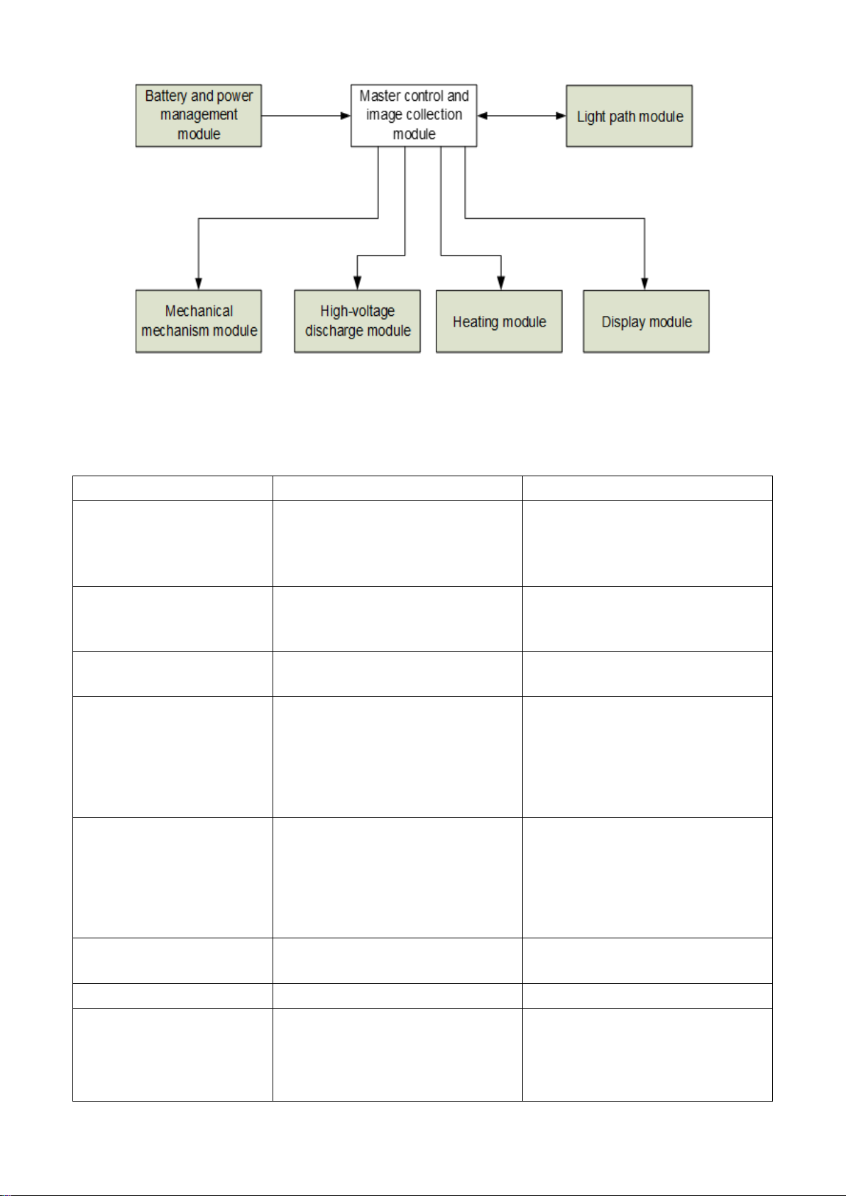
2 Functional Block Diagram ........................................................................................................................... 1
3 Common Fault ............................................................................................................................................ 2
3.1 Common Faults of Instrument............................................................................................................. 2
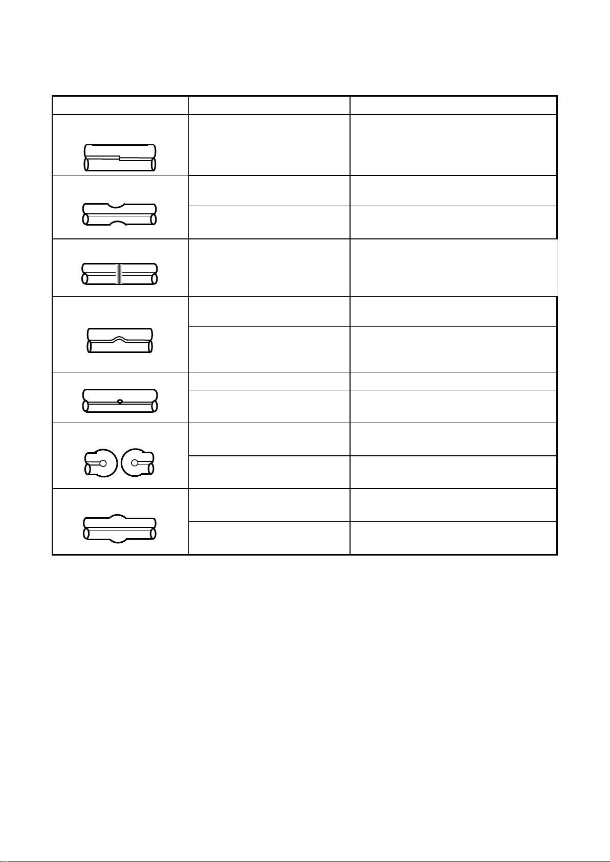
3.2 Causes of Fusion Loss Increase and Solutions ..................................................................................... 3
4 Repair of Parts ............................................................................................................................................ 4
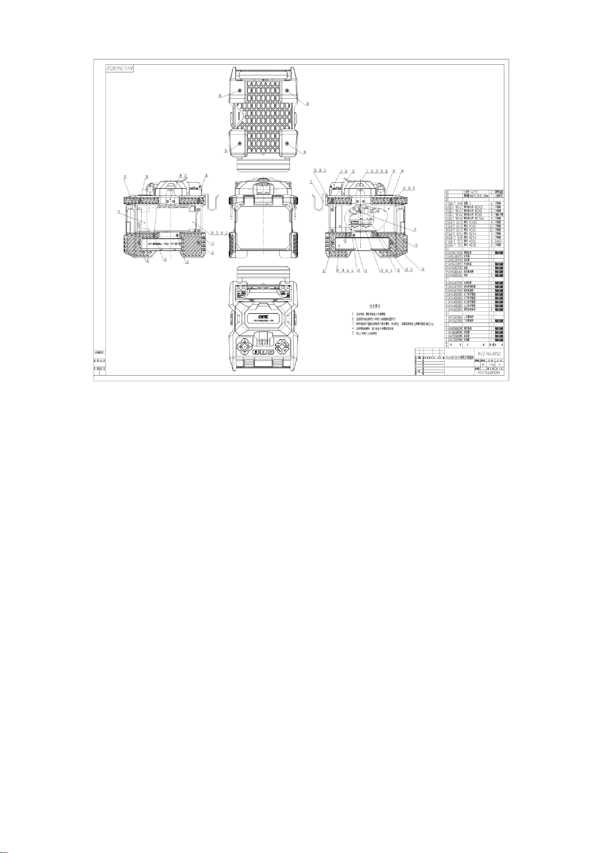
4.1 Disassembly ......................................................................................................................................... 4
4.2 Propel Motor ....................................................................................................................................... 5
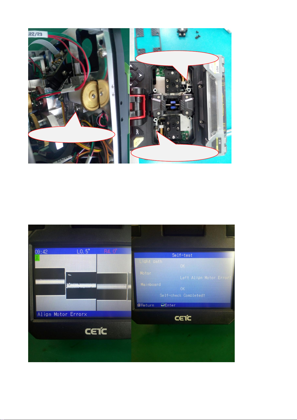
4.3 Align Motor.......................................................................................................................................... 8
4.4 Imaging Lamp .................................................................................................................................... 10
4.5 Heater ................................................................................................................................................ 15
4.6 Power Board ...................................................................................................................................... 16
4.7 High-voltage Board ............................................................................................................................ 17
4.8. Control Board ................................................................................................................................... 18
4.9 Light Path........................................................................................................................................... 20
5 Repair and calibration of Instrument ....................................................................................................... 21
5.1 Software Upgrade.............................................................................................................................. 21
5.2 Cleaning of V-groove ......................................................................................................................... 22
5.3 Cleaning and Replacement of Electrode ........................................................................................... 23
5.4 Adjustment of Electrode Holder........................................................................................................ 24
5.5 Cleaning of Objective Lens ................................................................................................................ 25
5.6 Propelling Distance Correction.......................................................................................................... 25
5.7 Propelling Distance Test .................................................................................................................... 26
5.8 Discharge Correction ......................................................................................................................... 26
5.9 Discharge Test.................................................................................................................................... 26

1
1 Product Introduction
This manual applies to the repair of fiber fusion splicer 6481. The fiber fusion splicer is mainly used for
the permanent connection of fiber and is widely used in the production test of fiber communication
engineering and optical passive devices. This product is applicable for connecting the single-mode,
multi-mode, non-zero dispersion, dispersion displacement and bending insensitivity and other quartz
fibers with a cladding diameter of 80μm ~ 150μm. The fusion splicer realizes the integration of optics,
mechanics and electronics, and it shall be kept clean and from strong vibration or shock during use. The
appearance of fiber fusion splicer 6481 is as shown in Fig.1.
Fig.1Appearance of fiber fusion splicer 6481
2 Functional Block Diagram
Basic working principle of the whole machine is as shown in Fig.2. The high-brightness light source is
used to illuminate the fiber, and the fiber is imaged on the CMOS sensor via a special microscope. The
image characterizes the physical and geometrical positions of the fiber in two directions which are
perpendicular to each other. The two-way fiber images are processed and spliced by FPGA and then
sent to LCD through theARM system.
CPU system analyzes and processes the image signals to generate various prompting and control
signals. The prompting information is displayed simultaneously with the real-time fiber image. Control
signals drive two propel motors to get two fibers to approach to each other, and then drive two displace
motors to align the fiber core or cladding face in a two-dimensional plane. The discharge signal is given
to the high-voltage board to generate a certain high voltage, and an arc is generated across the
electrodes. The fiber is permanently connected through the high temperature of arc. Finally, the current
fusion loss is calculated according to the physical properties of spliced fiber image, and is displayed on
the screen. In the actual construction process, the heat-shrink protection is conducted for the bare fiber
which is connected successfully through the heater.

2
Fig.2 Block diagram of whole machine
3 Common Fault
3.1 Common Faults of Instrument
Table 1 Common faults of Instrument
Phenomenon
Cause
Repair method
Failure to start
1. Damage of battery or adapter
2. Power board cable not plugged
3. Power board damage
4. Control board damage
1. Replace the battery or adapter
2. Plug in the power board cable
3. Replace the power board
4. Replace the control board
Flower or white screen at
start
1.Display cable not plugged
2. Damage of display cable or
cable socket
1. Plug in the display cable
2. Replace the display cable or
cable socket
No respond from button
1. Button cable not plugged
2. Damage of button board
1. Plug in the button cable
2. Replace the button board
Abnormality of touch screen
1. Turnoff of touch screen function
in the menu
2. Touch screen not calibrated
3. Touch screen cable not plugged
4. Damage of touch screen cable
or touch screen
1. Open the touch screen function
in the menu
2. Calibrate the touch screen
3. Plug in the touch screen cable
4. Replace touch screen cable or
touch screen
Black screen of X/Y camera
1. Imaging lamp cable not
plugged
2. Damage of imaging lamp
component
3. Hall switch cable not plugged
4. Damage of Hall switch
1. Plug in the imaging lamp cable
2. Replace the imaging lamp
component
3. Plug in the Hall switch cable
4. Replace the Hall switch
Charging failure
1. Damage of battery
2. Damage of power board
1. Replace the battery
2. Replace the power board
Flashing of charge indicator
Damage of power board
Replace the power board
White screen, discharging
at start, and restart of
instrument when the
windshield is opening or
closing
Damage of imaging lamp
component
Replace the imaging lamp
component

3
X/Y camera too bright or too
dark
Incorrect setting of CMOS gain
Reset the gain value
Abnormal display of X/Y
camera
1. Camera plate cable not
plugged
2. Damage of camera plate or
control board
1. Plug in the camera plate
cable
2. Replace the camera plate or
control board
Left/right motor error at start
1. Propel motor cable not plugged
2. Foreign material between
propel motor gears
3. Jam of propel motor
1. Plug in the propel motor cable
2. Clean up the foreign objects
3. Replace the propel motor
Abruption or abnormal
noise of propel motor
1. Foreign objects between the
propel motor gears
2. Propel motor fault
1. Clean up the foreign objects
2. Replace the propel motor
"Displace motor error X/Y"
at aligning
1. Align (displace) motor cable not
plugged
2. Jam of align (displace) motor
1. Plug in the align (displace)
motor cable
2. Replace the align (displace)
motor
No discharge
1. High-voltage discharge plate
cable not plugged
2. Damage of high-voltage
discharge plate
1. Plug in the high-voltage
discharge plate cable
2. Replace the high-voltage
discharge plate
Discharge to V-groove
Offset of electrode position
Adjust the electrode position
Weak or unstable discharge
1. Improper setting of discharge
parameters
2. Dirty electrode
1. Adjust the discharge parameters
or perform the discharge correction
2. Clean or replace the electrode
Heater failure
1. Heater cable not plugged
2. Heater damage
1. Plug in the heater cable
2. Replace the heater
Auto heating failure if the
heater cover is closed
1. Manual operation of heater
2. Damage of heater optical
switch
1. Set it to auto
2. Replace the heater
Fiber not held by heater
cover
Magnetic steel shedding
1. Re-bind the magnetic steel
2. Replace the heater
Fiber not held by fixture
pressure plate
1. Fixture magnetic steel
shedding
2. Upper and lower sliders not
came out
1. Re-bind the magnetic steel
2. Replace the fixture
Obvious tilt of X/Y fiber
image
Minor changes in camera plate
position
Re-adjust the camera plate
Dark spots or shadows on
X/Y video background
Dirt on the X/Y microscope lens or
CMOS surface
Clean the lens or CMOS
3.2 Causes of Fusion Loss Increase and Solutions

4
Table 2 Causes of Fusion Loss Increase and Solutions
Phenomenon
Cause
Solution
Axial misalignment of fiber
core
Dirty V-groove or fiber presser
Clean V-groove and fiber presser
Too fine
Improper discharge current
intensity
Discharge Correction
Too short propelling distance
Correct the propelling distance or
increase the size of overlap
Black line pattern
Incorrect fusion parameter
Check whether the fusion mode is
correct
Adjust the current intensity and
discharge time
Fiber core bending
Poor quality of fiber
cross-section
Check the cutting quality of fiber cutter
Small discharge current
intensity or longer propelling
distance
Correct the discharge or propelling
distance
Adjust the propelling distance
Bubble
Dirty fiber cross-section
Check the cutting quality of fiber cutter
Small discharge current or
decreasing discharge time
Discharge Correction
or increase the fusion time
Fiber separation
Too short propelling distance of
fiber
Correct the propelling distance
or increase the size of overlap
Too large discharge current or
too long discharge time
Discharge Correction
or reduce the discharge time
Too rough
Too long propelling distance of
fiber
Correct the propelling distance
or reduce the size of overlap
Too small discharge current
Discharge Correction
or increase the fusion current
4 Repair of Parts
4.1 Disassembly
First power off, and remove the protective soft rubber and the screws on the front and rear covers with
an Allen screwdriver to disassemble the entire instrument, and do not drop the screw into the inside of
instrument. As shown in Fig.3, three specifications of the screws on the protective soft rubber shall be
distinguished for installation (especially four screws on the bottom are M3X6).

5
Fig.3 Overall appearance of instrument
4.2 Propel Motor
If “Left/right motor error” is displayed at the lower left corner of screen during the startup (as shown in
Fig.4), the propel motor may be stuck. In most cases, the jam of motor is caused by the foreign objects
between two gears of propel motor which may lead to the starting or propulsion failure. Repair steps are
as follows:
①Open the windshield and remove the fixture and pressure plate.
②As shown in Fig.5, there are foreign objects between the gears of propel motor. Clean the
foreign objects.
③Start the instrument, and when the propel motor is stuck, manually assist the motor to smoothly
pass the jam and enable the instrument to normally start.
④Press the "Menu" button to enter the menu page, select "maintenance" ---> "motor" ---> "motor
adjustment", and select the left or right motor to be cleaned via the "Enter" button.
⑤Operate the "Left" and "Right" buttons to locate the different parts of micrometer head of propel
motor for the convenient cleaning.
⑥Gradually clean the foreign objects in various parts of micrometer head with the cotton stained
with alcohol held by tweezer.
Clean the foreign objects according to the above six steps, so as to solve the jam of propel motor,
reinstall the pressure plate and fixture, and complete the repair.
If the jam still exists, you can remove the screws of propel motor (see Fig.6) and replace the propel
motor.

6
Fig. 4 Jam of propel motor

7
Fig.5 Cleaning of foreign objects between motor gears
Dust accumulates between
gears, sometimes the foreign
objects such as the exterior
protection cover is stuck.
The dust on the fitting part
between the propel threaded
rod and screw sleeve results
in the stagnation

8
Fig. 6 Positions of propel motor screws
4.3 Align Motor
In case of the displace motor error during the normal use or the align motor error during the self-test (as
shown in Fig.7), the align motor has failed. Check the meshing between the align motor gear and the
align micrometer head gear, and if it is too tight or shafts are not parallel, adjust the relative positions by
loosening the screws of align motor (see Fig.8); or if the micrometer head does not rotate smoothly,
remove the align motor, and then manually toggle the micrometer head of align motor (see Fig.9) until
the rotation is smooth; if the problem still exists, replace the align motor.
Fig.7 Jam of align motor
Screw of propel motor

9
Fig.8Align motor
Screws of align motor

10
Fig.9Align micrometer head
4.4 Imaging Lamp
White screen, sometimes with the discharge, occurs at the startup, or the instrument restarts when the
windshield is opened or closed, or X/Y camera looks like black screen after the windshield is closed, it
may be that the imaging lamp cable is damaged at the spindle or the imaging lamp cable is broken at the
weld point of printed board, the imaging lamp and spindle shall be replaced.
①As shown in Fig.10, remove the limiting plate of sketch mounting plate to present the imaging
lamp, and remove 4 screws fixing the imaging lamp (Fig.11).
②As shown in Fig. 12, pull out X26 plug and jet out X26 pin from plug with tweezer and do not
discard the plug.
③Pull out the X26 cable from the spindle, and cut it directly if it is not easy to pull out.
④As shown in Fig. 13, remove the spindle with a flat-blade screwdriver and replace it with a new
one.
Align micrometer head

11
⑤Replace it with new imaging lamp, screw down 4 screws fixing the imaging lamp, insert the
imaging lamp cable into two heat-shrink tube, and fit the imaging lamp cable into the spindle.
⑥The heat-shrink tube on the heat-shrink imaging lamp cable is as shown in Fig.14.
⑦Insert the pin of imaging lamp cable into the plug that has just been removed (the cable is black,
white and blue in sequence from the inside to the outside), and then insert the plug into X26
base.
⑧Install the sketch mounting plate.
Fig.10 Sketch mounting plate
Limiting plate of sketch
mounting plate

12
Fig.11 Imaging lamp
Screws fixing the
imaging lamp
Cable at spindle
may be damaged
Weld point may
be broken

13
Fig.12 X26 cable
X26 cable is black, red,
white and blue in
sequence from the
inside to the outside
Jet out the pin of
X26 cable out of
plug and do not
discard the plug

14
Fig.13 Replacement of spindle

15
.
Fig.14 Installation of imaging lamp
4.5 Heater
If the heater does not work or can not automatically heat (automatic heating function is on in the menu),
first check whether cables X11 and X12 of control board are plugged in. If they are plugged in, it means
that the heater is damaged and shall be replaced. Unplug cables X11 and X12, and remove the fixing
screws of heater (Fig. 15) to replace the heater.
Fit the cable
through here

16
Fig.15 Heater
4.6 Power Board
In case of the failure to start, charge or the flashing of charge indicator, the power board may be
damaged. If the instrument fails to start, first check whether the cables of control board X1 and power
board X3 are plugged in. If they are plugged in, remove 4 screws on the bottom of instrument (as shown
in Fig.16) and gently pull out the base of instrument with care not to damage the cable X2, pull out
cables X2 and X3, measure whether there is 12.6V output at pins 1 and 4 of cable X3 (as shown in
Fig.17); if so, the power module is not damaged; if not, the power module is damaged, and proceed to
the determination whether the power board or battery is damaged. If the power board is damaged,
remove the screws on the power board to replace the power board.
The charge failure may be caused by the damage of battery or power board. To find out the cause, insert
the good-working battery which is fully charged into the instrument, start the system and observe the
battery icon at the upper right corner of screen, and if no lightning symbol is shown on the icon, it means
that the power board is damaged; or measure the voltage on both sides of R9 on the back of power
board, and if there is no charge voltage (less than 0.1V), the power board is damaged.
Fixing screws of
heater

17
Fig.16 Removal of base
Fig.17 Power board
4.7 High-voltage Board
In case of no discharge, check whether the connecting cables between the high-voltage board X1 and
the control board X7 and between the high-voltage board X2 and the control board X6 is off or loose.
Make sure that the connection is normal. If the discharge failure still exists, the high-voltage board is
damaged. Replace the high-voltage board by pulling out the cables X1 and X2 of high-voltage board,
removing two high-voltage wires (on the front and back) and fixing four screws on the high-voltage board
(as shown in Fig.17). Because there are many cables passing between the high-voltage board and align
motor, be careful not to hold down the other cables when installing the high-voltage board.
Power board X3
Back of power
board R9
X2 cable

18
Fig.17 High-voltage board
4.8. Control Board
In case of starting failure, check whether the control board FPGAload indicator V17 (as shown in Fig.18)
is on. If not, the control board is damaged. Pull out all the cables on the control board, and remove the
stopper fixing the control board (as shown in Fig.19) by extracting the control board if necessary.
In case the white screen at start, pull up the plug of X26 cable (imaging lamp) on the control board, and
then restart the instrument. If the white screen disappears, it means that the control board is normal, and
check whether X26 cable is damaged. If so, replace the imaging lamp.
In case of flower screen, check whether the LCD cable and socket X4 are loose. Try to re-insert LCD
cable to correct the flower screen, and if not, replace the LCD cable.
High-voltage wire
Other manuals for 6481 Series
1
Table of contents