45
OOPPEERRAATTIIOONN
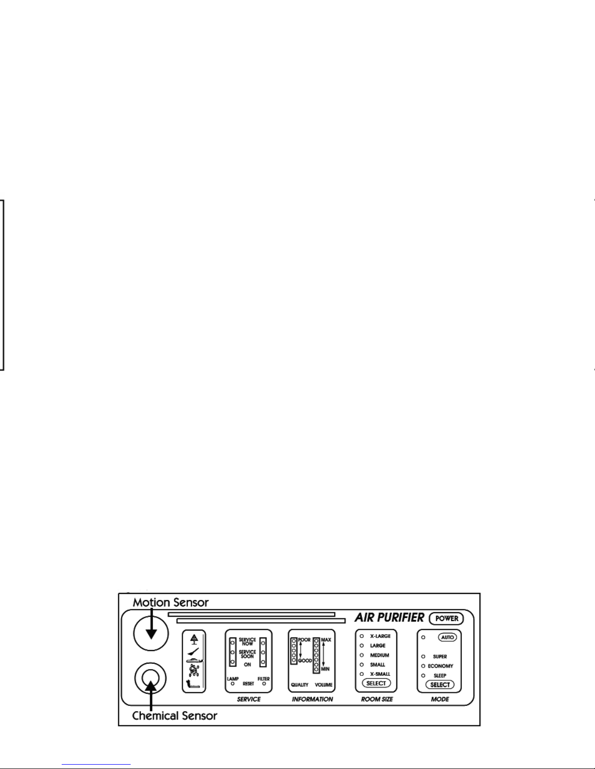
SSEELLEECCTTOOPPEERRAATTIINNGGMMOODDEE
Select the desired operating mode by pressing the
SSEELLEECCTTbutton on the MMOODDEEpanel (Fig. 3).
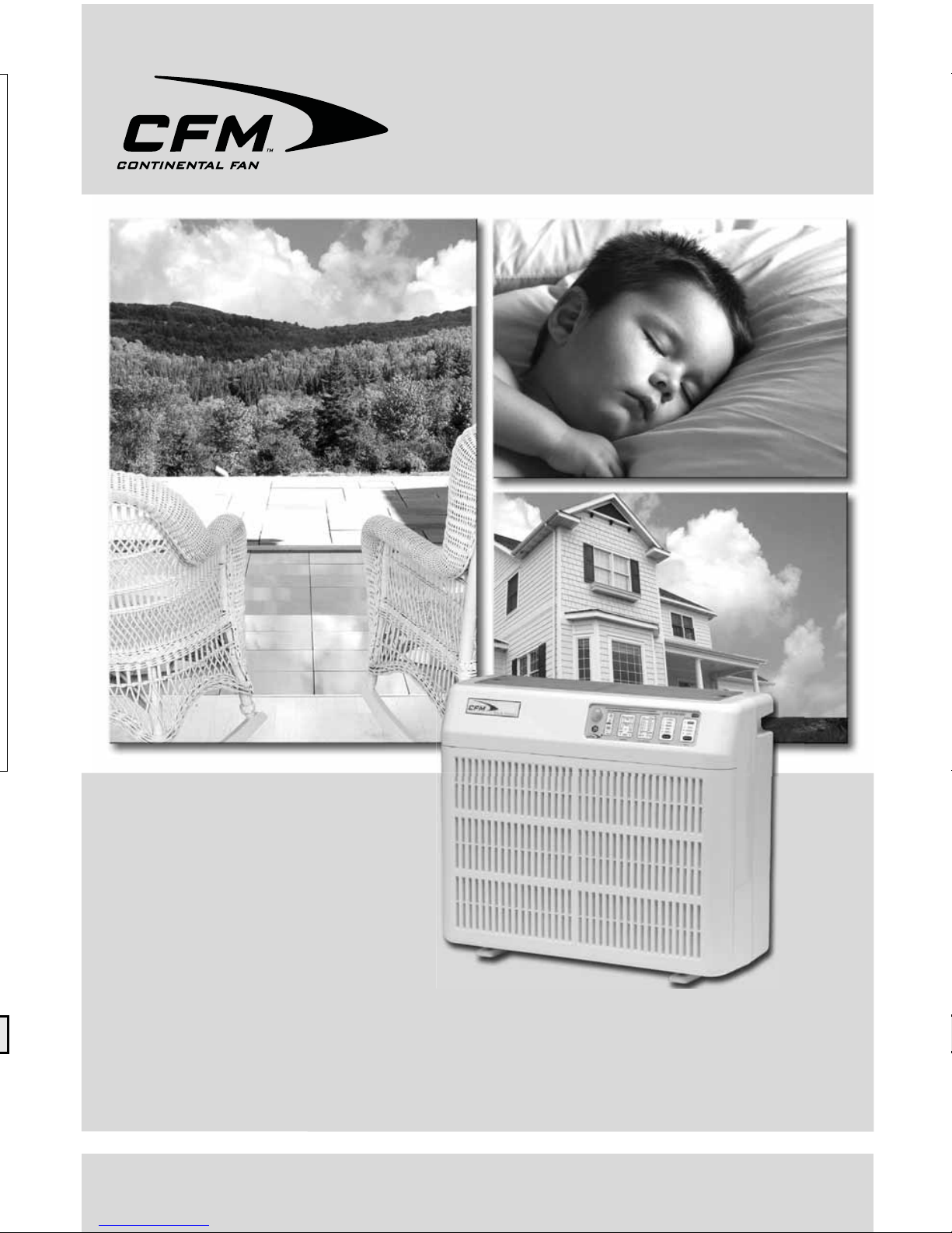
AAUUTTOO----In AAUUTTOOmode, the Chemical Sensor
controls the blower speed (see Fig. 1). If the sensor
detects an unhealthful amount of chemicals present
in the air (indicated by the red light on the QQUUAALLIITTYY
scale), the blower speed will automatically increase.
SSUUPPEERR----SSUUPPEERRmode may be selected during
periods of high air pollution, such as when winds
increase airborne dust and pollen, or during heavy
room loading (parties or smoking). Blower speed
will increase 25 percent above AAUUTTOOmode.
EECCOONNOOMMYY----E
ECCOONNOOMMYYmode saves energy when the room is unoccupied.
When the MMoottiioonnSSeennssoorr(see Fig. 1) detects no motion for 30 seconds, blower
speed is reduced to save electricity costs. The blower returns to normal speed
when motion is again detected.
SSLLEEEEPP----SSLLEEEEPPmode reduces the sound level by slowing blower speed by 30
percent, while still purifying room air at 70 percent of normal operation.
MMOONNIITTOORRIINNGGOOPPEERRAATTIIOONN
The Chemical Sensor continually monitors air
QQUUAALLIITTYY, and in AAUUTTOOmode, controls blower
speed and air volume.
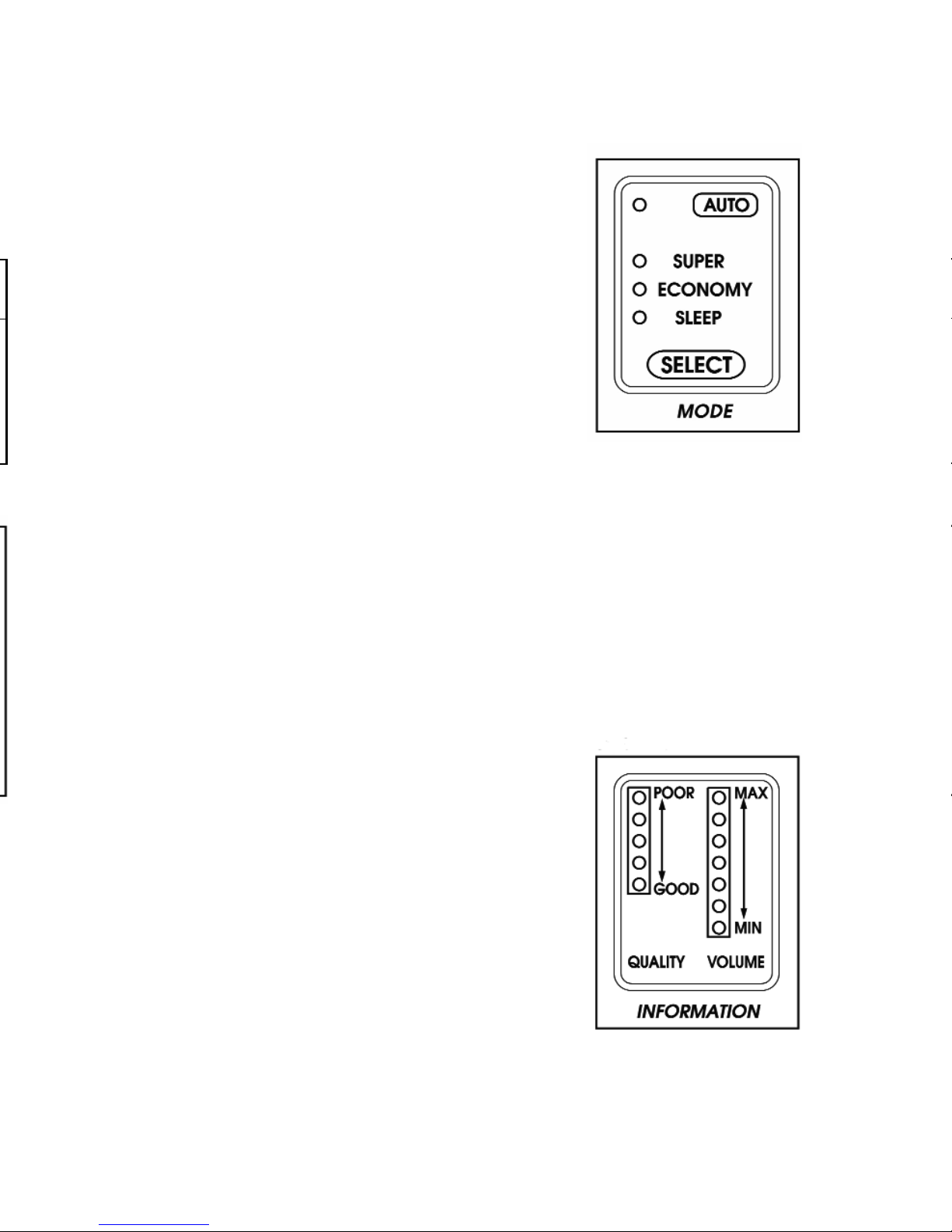
Both air QQUUAALLIITTYYand air VVOOLLUUMMEEare displayed on
the IINNFFOORRMMAATTIIOONNpanel (Fig. 4).
Air QQUUAALLIITTYYis indicated by one of five lights,
indicating a range from GGOOOODDto PPOOOORR.
Air VVOOLLUUMMEEis indicated by one of seven lights,
representing a range from MMAAXXto MMIINN.
Set the CCXX11000000to move a volume of air appropriate
for room conditions. Note that measurements are relative to the selected room
size. Make sure that the RROOOOMMSSIIZZEEsetting (see Fig. 2) is always set for the room
in which the unit is to operate.
Fig. 4
OOPPEERRAATTIIOONN
SSEELLEECCTTRROOOOMMSSIIZZEE
1. Determine the area of the room in which the CCXX11000000PPoorrttaabblleeAAiirrPPuurriiffiieerris
to operate.
2. From the charts below, identify the respiratory condition the unit is to serve.
3. The HHEEAAVVYYDDUUTTYYchart is used for people that
have severe respiratory problems, or suffer
allergic reactions when exposed to particulate
matter (pollen, dust, dust mites, animal dander,
etc.) or airborne chemicals (pesticides, herbicides,
cleaning solutions, etc.).
4. The LLIIGGHHTTDDUUTTYYchart is used for people that
occasionally suffer from mild allergies, or to
help purify the air in an average home.
5. Select the appropriate RROOOOMMSSIIZZEEby
repeatedly pressing the SSEELLEECCTTbutton (Fig. 2).
Fig. 3
Fig. 2
HHEEAAVVYYDDUUTTYY
AAUUTTOOMMOODDEESSQQ..FFTTSSQQ..MMEETTEERRSS
OOXX--LLAARRGGEE5555005555
OOLLAARRGGEE4455004455
OOMMEEDDIIUUMM4400004400
OOSSMMAALLLL3355003355
OOXX--SSMMAALLLL3300003300
LLIIGGHHTTDDUUTTYY
AAUUTTOOMMOODDEESSQQ..FFTTSSQQ..MMEETTEERRSS
OOXX--LLAARRGGEE11770000117700
OOLLAARRGGEE11445500114455
OOMMEEDDIIUUMM11220000112200
OOSSMMAALLLL11005500110000
OOXX--SSMMAALLLL9900009900