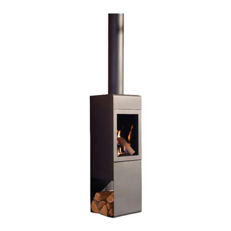
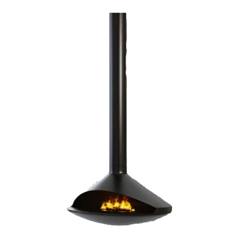
CF+D VITA LUCIJA Operating instructions

VITA | Fireplaces
North American Designed & Manufactured by CF +D | custom replace design
LUCIJA
Suspended Fireplace with Vapor-Fire Burner
INSTALLATION | OWNER'S MANUAL
Serial #
Read full manual before installation and keep all instruction for future use
1/22/19
CF + D | custom replace design
www.customreplacedesign.com

Table of Contents
APPENDIX A - VITA | Fireplaces Installation
Important Instructions................................................................................................................Page A
General Information....................................................................................................................Page B
Fireplace Specications...............................................................................................................Page C
Installation Requirements...........................................................................................................Page D
a) Installation Requirements
b) Required Tools
c) Description
Anchor Plate Installation.............................................................................................................Page E
Anchor Plate Options Diagram.................................................................................................Page F
Flue Pipe Installation....................................................................................................................Page G
Flue Pipe Extension Instructions..............................................................................................Page H
Trim Collar Installation...............................................................................................................Page H
Fireplace Body Installation.........................................................................................................Page H
Electrical Installation...................................................................................................................Page I
Plumbed-In Option Instructions...............................................................................................Page I
Media Plate Instructions.............................................................................................................Page I
Initial Fill Instructions..........................................................................................................Page J & K
Manual Fill Option Instructions................................................................................................Page K
Glass Panel Installation...............................................................................................................Page L
Warranty Statement....................................................................................................................Page M
APPENDIX B - Vapor-Fire Service Manual........................................................Pages 1 - 15
1/22/19

A Letter from Our President:
Our entire team joins me in thanking you for purchasing the LUCIJA Suspended
replace, part of our exclusive line of VITA | Fireplaces featuring Vapor-Fire burner
technology, North American designed and manufactured by CF + D | custom replace
design. We are proud of our quality workmanship, our creativity in designing functional
art pieces and our commitment to technical innovation. We welcome the challenges that
come across our designer’s desks, keeping our creative minds working on developing new
ideas with our clients to build their dream re feature.
Upon receiving this letter your VITA Fireplace has now been shipped and received.
The installation, technical and service manuals are included in the package and our
Technical Team is available with assistance throughout the installation and start-up of your
new VITA replace.
The Management, Designers and our Metal Craftsman, thank you again for the
opportunity of being a part of your project. We value our clients greatly and are available
for consultation before, during and after the installation of your exclusive VITA replace.
Vince Volpe
President and CEO
CF +D | custom replace design
5230 Harvester Rd. Unit #2 Burlington, Ontario Canada
L7L 4X4 t. 1-866-909-3070 t. 905-681-3070
www.customreplacedesign.com
Quality Creativity Innovation
VITA | Fireplaces Installation
1/22/19

APPENDIX A - Important Instructions
- Page A -
1. Not for use outdoors.
2. DO NOT insert or allow foreign objects to
enter any ventilation or exhaust opening as this may
cause electric shock.
3. DO NOT block air intakes or exhaust in any
manner.
4. DO NOT use in area where gasoline, paint or
ammable liquids are used or stored.
5. DO NOT burn wood or other materials in this
model.
6. Always USE A CERTIFIED ELECTRICIAN
should new circuits or outlets be required.
7. DISCONNECT THE POWER SUPPLY
BEFORE DOING ANY CLEANING,
MAINTENANCE OR RELOCATION OF
THE MODEL.
8. To disconnect the model, turn the controls off
and disconnect the power at the service panel.
A dedicated 15 Amp, 120V GFCI is
required for electrical.
Vapor-Fire Burner:
This equipment has been tested and found to
comply with the limits for Class B digital device,
pursuant to part 15 of the FCC Rules. These limits
are designed to provide reasonable protection
against harmful interference.
Construction and electrical outlet wiring must
comply with local building codes and other
applicable regulations to reduce the risk of re,
electric shock and injury to persons.
9. Tethered Bluetooth control boxes are connected
before shipping to ensure proper operation. Also
used to sync the remote control for remote
operated units. Make sure they are all rmly plugged
in for the unit to work properly. They may have
become loose during shipping.
DO NOT REMOVE OR
DISCONNECT THE TETHERED
BLUETOOTH DEVICE FROM
INSIDE THE UNIT. It has been factory set to
ensure proper operation.
IMPORTANT: Read all instructions before installation.
Electrical Dedicated Switch Operation
Recommended for all applications in Commercial Projects
Remote Controls are available upon request
1/22/19

- Page B -
1/22/19
General Information
KEEP THIS MANUAL HANDY FOR EASY REFERRAL.
All WARNING and CAUTION SHOULD BE STRICTLY OBSERVED.
Please read this entire manual before you
install and use your VITA | Fireplaces Vapor-Fire
Feature.
Failure to follow the instructions may result
in property damage, bodily injury or even death.
When this re feature is not properly
installed, a re may result. To reduce the risk of re,
follow the installation instructions.
This service bulletin is to serve as a guide
to the installation and operation of your replace
system. It is not intended to replace skilled trades
and/or expertise that may be required to perform
installations.
All electrical and electronic components
must be installed, inspected and tested by qualied
persons in accordance with local building codes.
Components described herein are intended
as an indication of the components required and/or
supplied and is not an exhaustive item listing.
All standard safety practices as indicated
by local codes, laws, or OSHA standards must be
followed to prevent accident or injury.
Some of the components supplied cannot
be installed by a single person nor should they be
installed from a ladder.
All site safety arrangements are the
responsibility of the Site Supervisor, General
Contractor and/or Fireplace Installers, and not
CF + D.
USING MAKE-SHIFT COMPROMISES
DURING INSTALLATION CAN CAUSE
DAMAGE. Such installation is not covered under
CF + D limited warranty.
DO NOT CONNECT TO ANY AIR
DISTRIBUTION DUCT OR SYSTEM!
CF + D specializes in creating one-of-a-
kind, hand-made artistic replaces. While these re
features are generally developed for their aesthetic
presence, they are also a functional appliance. As
such, natural variations in the material forming
processes and patina are part of the sculptural
spirit of the replace, adding to the beauty and
uniqueness of the design.

Fireplace Specications
- Page C -
LUCIJA
Sample Layout
1/22/19
(TOP OR SIDE)
TOP GLASS
FLUE PIPE
ANCHOR
BODY
DOOR
PLATE
(CONICAL)
SERVICE
REMOVABLE
ANCHOR
COLLAR
PIPE
(STRAIGHT)
FIREPLACE
BODY
TRIM
JUNCTION
BOX
FLUE
MEDIA
TRAY
ELECTRICAL &
WATER LINE
OPENING
SIDE FLAT
GLASS FINISHED FLOOR
WATER SUPPLY
JUNCTION BOX
ELECTRICAL LINE
POWER SUPPLY CONTINUOUS
(OPTIONAL)
SERVICE DOOR
TRIM COLLAR
OF 50 SQ. IN REQUIRED
MIN AIR VENTILATION
30.5" FIREPLACE
AIR OUT
OPENING
FINISHED CEILING
8-5/8" ANCHOR
BODY
24"SQ. ANCHOR
22"
PLATE
343
8"
FINISHED CEILING
FINISHED FLOOR
108"
7"
AIR INLET
FINISHED CEILING
11"
FINISHED FLOOR
13"
TO
5"14 8
8"
"
8
28"
83
5
313
8"
Shown with Standard 9ft. Flat Ceiling Application
Custom Lengths and Anchor Options Available

Installation Requirements
- Page D -
INSTALLATION | OWNER'S MANUAL
LUCIJA Suspended Fireplace with Vapor-Fire Burner
B) Required tools
• Drill
• M8 Allen key
• Level
• Screw drivers
• M12 Allen key
• Scaffolding if necessary
• 2 persons minimum are required for installation.
A) Installation Requirements
• Prepare ceiling for the installation of the anchor
plate (see Anchor Plate Options Page F).
• Electrical 15 AMP Service 120V GFCI at ceiling
ready for anchor plate placement and the
supplied wiring and junction box connections.
• If the client has chosen the option of
continuous water, a plumbed-in ½” water line
for continuous water ow from the ceiling is
required which will connect to the ¼” plumbing
line supplied with the replace. The water shut
off is located at the plumbing connection. (See
Instructions Pages I - J).
• For manual ll operation, two water containers
will be supplied with the unit for manual relling
(See Instructions Page K).
C) Description
Fireplace Body Weight 150 lbs.
Flue Diameter 8”
Flue Length Made to specication
Fireplace Body Diameter 28”
Flue Weight 11 lbs. per foot
Number of Glass Panels 4
Standard Anchor Plate Weight Approx. 77 lbs. - Heavy Gauge steel
1/22/19

Anchor Plate Installation
- Page E -
The rst step is to install the anchor plate.
The anchor plate will hold the weight of the
replace and suspend it from the ceiling or roof.
The anchor body has an access/service panel. The
anchor plate should be secured in place and the ue
pipe should hang level and plumb (straight).
A supported opening in the roof or ceiling
to accommodate the anchor plate will be required.
Adequate and approved structural methods must be
used when mounting the anchor for it to carry its
designated load.
Before starting, verify the location of the
ue pipe and replace body and the point at which
the anchor plate will be positioned. Lift the anchor
plate into position to be placed in the prepared
supported ceiling or roof. Depending on your
application refer to your specic layout drawing for
custom anchor plate installation (See Anchor Plate
Options Diagram Page F).
CAUTION! THE SUPPORT OF THE
ANCHOR PLATE (ROOF
STRUCTURE, SLAB, ETC.) MUST
BE SIZED IN ACCORDANCE WITHTHE
STATIC AND DYNAMIC LOADS OFTHE
FIREPLACE.THE SIZE CALCULATION
FOR THE SUPPORT IS NOTTHE
RESPONSIBILITY OF CF + D OR ITS
AFFILIATES. IT ISYOUR RESPONSIBILITY
TO CONSULT WITH AN ENGINEER OR
ARCHITECT FORYOUR PROJECT.
Place the anchor in the desired location and
mount it to the ceiling using ½” screws.
The anchor will support the weight of the
ue pipe and the unit. Screws must be mounted into
studs or solid substrate. (Figure 1)
Figure 1
Install the Anchor Plate
CAUTION! Use multiple people,
or portable crane to move replace
into position.
1/22/19

Anchor Plate Options Diagram
- Page F -
24" SQ.
ANCHOR PLATE
5"
?
CEILING
THICKNESS
13"
6"
?
SLOPE
?
FINISHED FLOOR TO
FINISHED CEILING
HEIGHT
FINISHED CEILING
TRIM COLLAR
SERVICE DOOR
JUNCTION BOX
FLOOR/ROOF
ABOVE
POWER SUPPLY
(ELECTR I CAL LINE IN)
CONTINUOUS WATER
SUPPLY (OPTIONAL)
JOIST
8-5/8" ANCHOR BODY
8" FLUE PIPE
FINISHED
FLOOR
OPTION A - SLOPED DROP FROM ABOVE
24" SQ.
ANCHOR PLATE
13"
6"
5"
?
CEILING
THICKNESS
?
FINISHED FLOOR TO
FINISHED CEILING
HEIGHT
CONCRETE STRUCTURE
FINISHED
CEILING
TRIM COLLAR
SERVICE DOOR
JUNCTION BOX
OPTION B - SUSPENDED FROM CONCRETE
POWER SUPPLY
(ELECTRICAL LINE IN)
CONTINUOUS WATER
SUPPLY (OPTIONAL)
THREADED ROD FOR
SUSPENDING ANCHOR PLATE
FROM CONCRETE STRUCTURE
8" FLUE PIPE
8-5/8" ANCHOR BODY
FINISHED
FLOOR
24" SQ.
ANCHOR PLATE
13"
6"
5"
?
CEILING
THICKNESS
?
FINISHED FLOOR TO
FINISHED CEILING
HEIGHT
CONCRETE STRUCTURE
FINISHED
CEILING
TRIM
COLLAR
SERVICE DOOR
JUNCTION
BOX
POWER SUPPLY
(ELECTRICAL LINE IN)
CONTINUOUS WATER
SUPPLY (OPTIONAL)
OPTION C - ATTACHED BELOW CONCRETE
THREADED ROD FOR
SECURING ANCHOR PLATE
TO CONCRETE STRUCTURE
FINISHED
FLOOR
8-5/8" ANCHOR BODY
8" FLUE PIPE
1
3
4
" TYP.
1
3
4
" TYP.
24"
24"
5
8
" TYP.
ANCHOR PLATE
24" SQ. x 0.25" THK.
ELECTRICAL &
WATER LINE
OPENING
(TOP)
CUSTOM ANCHOR OPTIONS AVAILABLE
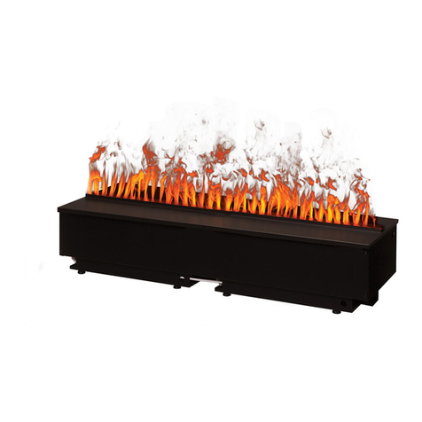
Vapor-Fire burner technology
•
Realistic flame without heat
•
No venting requirements
•
Safe to the touch
•
Fueled by regular tap water
•
120 Volt 15 Amp-GFCI
•
All fireplaces come in black matte finish
•
Custom colors and patina finishes available
•
Heat available, most models
•
WATER SOURCE OPTIONS
OPTION 1: Plumbed-In to main source water line, ½”
reduced to ¼” factory set connection.
OPTION 2: Removable 1L container for manual fill
approx. 8-10 hour burn time.
Recommended : Leak detection sensor for potential leak
management.
Note: Exact measurements may vary
½”.
VITA
Fireplaces
LUCIJA
Suspended Fireplace with Vapor-Fire Burner
Product Information
North American Designed & Manufactured
by
CF + D
| custom fireplace design
UNLESS OTHERWISE SPECIFIED:
CHECKED
SIZE
TITLE:
PROPRIETARY AND CONFIDENTIAL
INTERPRET GEOMETRIC
TOLERANCING PER:
Q.A.
MP
FINISH
DWG. NO.
DATE
A
DIMENSIONS ARE IN INCHES
TOLERANCES:
FRACTIONAL
ANGULAR: MACH
BEND
TWO PLACE DECIMAL
THREE PLACE DECIMAL
0
MATERIAL
NAME
REV
DO NOT SCALE DRAWING
SCALE : NTS
SVF-08
ENG APPR.
THE INFORMATION CONTAINED IN THIS DRAWING IS THE SOLE PROPERTY OF
CUSTOM FIREPLACE DESIGN INC
.
ANY REPRODUCTION IN PART OR AS A WHOLE WITHOUT THE WRITTEN PERMISSION OF
CUSTOM FIREPLACE DESIGN INC
.
IS PROHIBITED.
MV
DRAWN
3/5/2019
3/5/2019
MFG APPR.
SHEET 3 OF 3
LUCIJA
MODEL:
CUSTOM ANCHOR OPTIONS
CF + D
CUSTOM FIREPLACE DESIGN INC.
5230 HARVESTER RD. UNIT # 2
BURLINGTON, ONTARIO CANADA L7L 4X4
PHONE: 905-681-3070 FAX: 905-681-8697
1/22/19

Flue Pipe Installation
- Page G -
To Install the ue pipe, raise the pipe up
to meet the anchor plate that has now been
positioned. The ue pipe is designed to t directly
into the anchor plate (Figure 2). The ue pipe will
also have the junction box attached for connection
once inserted into the anchor to meet the access
panel door.
NOTE: There are alignment marks on the ue and
the body right at the seam on the rear; align these
marks when installing the replace body to the
ue at what would be considered the rear of the
application.
Figure 2
There are 8, pointed load bearing set screws
installed into the anchor body and 2 stainless roll
(split) pins included in the package. The 8 set screws
are staggered in position. Begin by loosening each
set screw in the anchor body to maximize space
for the ue pipe to enter the anchor. Raise the ue
into the anchor body until it reaches a full stop just
before it reaches the access door (approximately 6”).
Install the Flue Pipe
To ensure that the ue pipe is hanging plumb
(straight) and level, use a Allen key to tighten
one screw until resistance is felt, then tighten the
screw directly opposite on the other side of the
ue until resistance is felt and continue. When all
8 screws are half tightened, check the position of
the ue and continue adjusting until the ue pipe is
perfectly plumb and level and is the desired distance
from the oor.
Once the ue is in perfect position,
completely tighten each of the 8 set screws rmly
securing the ue pipe into the anchor. Locate the
two ” pilot holes directly opposite each other in
the anchor body.
With a drill, pass a ” drill bit through each
pilot hole and through the ue. Hammer a roll (split)
pin (provided) through each hole until ush which
will permanently lock the ue pipe to the anchor
(Figure 3).
Figure 3
1/22/19

Flue Pipe Extension | Fireplace Body Installation
- Page H -
Install the Flue Pipe Extension
to Meet Ceiling Requirement
A ½" round rod is welded into the bottom
of the ue extension (See Figure 4 Below). The
top of the long ue pipe has laser cut outs to
accommodate the rod in the ue extension. You
can now raise the long ue pipe with the male
collar that has the laser cut outs in it, into the ue
extension pipe. Once raised, twist to pull the lower
section up and secure it into place.
Then insert a " roll (split) pin into the
holes on each side of the ue pipe to lock it in
place. The ue pipe extension is now connected.
Figure 4
Install the Trim Collar
Fit the trim collar (See Page C) around
the ue pipe and slide it upwards to meet the
nished ceiling. Afx the trim collar to the nished
ceiling either by using 4 screws (not provided), or
other means of attachment depending on your
requirements.
Install the Fireplace Body
Position the replace body with the Vapor-
Fire burner facing the desired direction and lift the
replace body directly under the ue pipe.
The electrical and water lines (if continuous
plumbing has been chosen) are supplied and found
coiled together inside the replace. Before attaching
the replace body to the ue pipe, uncoil the
lines and using sh tape pull the ¼” water line up
through the conduit in the ue pipe to its location
beside the junction box behind the shielded area.
Then pull the electrical wiring through the conduit
attached to the ue pipe up to the access door on
the anchor plate where the wire can be connected
to the junction box.
To complete the connection, lift the
replace body ensuring the alignment marks on the
seam between body and ue line up. Raise the body
until stop point. Place washers and nut through the
replace mouth and onto the protruding stud inside
the ue. Tighten the nut to ten-foot pounds of
torque.
NOTE: This operation will require multiple people.
It is suggested that two people lift the replace
body while a third completes the installation.
1/22/19

Electrical | Plumbed-In Option Instructions
- Page I -
Electrical Installation
NOTE: All electrical to be completed
rst. Do not turn on electrical until
plumbing has been completed.
The electrical and ¼” water line is supplied
with the replace.The electrical connections for
suspended replaces are located at the ceiling or
roof where the replace will be hanging. There is an
access/service panel provided on the anchor body
(see Figure 1), once the ue pipe has been inserted
into the anchor body, the junction box can be
accessed through this panel.
A dedicated circuit is required for the
junction box. Connect eld power 120V GFCI
wire,15 AMP service to the wires located on the
left side of the unit.
Be sure to include an on/off switch (on the
wall is recommended) into your power supply to
control the system.
NOTE: Make sure the Vapor-Fire
burner power is off before
connecting.
Media Plate Instructions
The media plate has three functions:
• The media plate will be lifted to access the
Vapor-Fire burner.
• To display the chosen media (rocks, glass, logs,
etc.).
• To direct the airow for optimum Vapor-Fire
effect.
1/22/19
There are two lifting tabs for ease of use (see
diagram below). Replace the media plate by holding
the top lifting tabs with the Vapor-Fire opening
facing upwards. Place the media tray into the slot
inside of the replace body. Ensure that all edges are
ush and snug so that the media plate is at.
Instructions for Continuous
Plumbed-In Systems
• The plumbing accessory kit is designed for use
with copper piping.
• Ensure that all plumbing connections meet local
plumbing code requirements.
• Ensure that the location of the plumbing
connection allows for easy access for shut-off
during scheduled maintenance.
Normal tap water can be used in theVapor-
Fire as long as the tap water is not considered to
be hard water. In the event your tap water is hard,
softened water is recommended.
NOTE: Plumbing connections should
be done by an experienced plumber
familiar with plastic tubing and
connectors.
Downsize the main ½" plumbing line to
¼" tube and connect to valve (¼" supplied and
connected to burner before shipping) which is

B)
Remove top cover assembly on the burner
by depressing side tabs gently (images 1 and 2).
1)
2)
It is now time to ll the water reservoir(s)
with 33.5oz (1L) of water. Take note of water level
markers (image 3 below). Be sure to ll water level
in between the markers in order for the system to
learn the proper level to maintain during operation.
3)
Replace the assembly making sure that
clips are secure and connect the plumbing ll cap
assembly (if applicable).
NOTE: this method does not use the orange
initial ll bottle.
Vapor-Fire Burner | Initial Fill Instructions
- Page J -
1/22/19
located in the front right corner of the burner on
the bottom. Test for water leaks and make sure
connections are leak proof.
Vapor-Fire Burner
Access the Vapor-Fire burner to complete
the initial ll process by lifting the media plate.
Remove media tray to access the burners (See Page
I). TheVapor-Fire burner is factory set and ready
for the initial ll. Conrm that all electrical and
plumbing have been completed before proceeding
to the next step.
Initial Fill Instructions
There are two ways to complete the initial
ll. Both are acceptable whether you have chosen
the plumbed-in or manual ll options.
Each VITA Fireplace is supplied with an
orange initial ll bottle which is used for priming
the reservoir, and/or on a regular basis (manual ll
option).
Option 1: Fill the reservoir directly
Remove the plumbing ll cap assembly
by gently twisting clockwise and move cap to
side (images A & B below). For manual ll VITA |
Fireplaces, there will not be a plumbing ll cap
assembly present.
A)

DO NOT attempt to test re the
system until all plumbing and
electrical is complete and the correct
starting water level has been established. Failure
to follow this instruction could incorrectly cause
overow during operation.
Instructions for Manual
Fill Containers
• Remove the media tray (top tray for rocks, logs
etc.) to access the burners.
• Remove the plastic container.
• Manually ll the supplied container with 1 litre
of water.
• Secure the top without twisting too tightly.
• Place the container back into position, the
water in the container will drain into the
reservoir which will ll to the level required
for maximum operation (See Picture 3 Page J).
• After the plastic container is empty or stops
owing into the reservoir, it has now lled to
the level required.
• Rell the container with water and replace
into position. The maximum operating cycle
time will be between 8 to 10 hours.
• Replace the media plate
• Now arrange your chosen media as desired
on top of the media plate. Use caution not
to overlap the Vapor-Fire opening as this can
interrupt the ame affect. Proceed to turn on
the Vapor-Fire replace.
Initial Fill (continued) | Manual Fill Instructions
- Page K -
Option 2: Fill the reservoir using the
Initial ll bottle
If you have chosen the plumbed-in
option, remove the plumbing ll cap assembly
(as outlined on Page J). If your VITA replace uses
the manual ll option, there is no plumbing ll
cap assembly.
Fill the orange initial ll container with
regular tap water and secure the cap without
twisting too tightly. Place the container into the
tray with the valve facing downwards as shown
below. The valve ts gently into the socket used
for the plumbing ll cap assembly (See Image B
Page J). No need to tighten.
Allow the water to drain into the
reservoir through the valve. You will hear a
gurgling sound. Once the water stops draining
into the reservoir below, the sound will stop.
This means that the Vapor-Fire reservoir has
lled to the optimal level.
NOTE: For plumbed-in option replace
the plumbing ll cap assembly and media
plate. For manual ll Vapor-Fire, re-ll
the initial ll bottle and keep for regular
operation.
1/22/19

Glass Panel Installation Instructions
1/22/19
- Page L -
NOTE: If after the test re stage,
the unit will be turned off to complete
construction, it is recommended to rst
drain all water from the reservoirs and/or rell
containers and dry to protect the transducers from
sitting idle in water for extended periods.
NOTE: The Vapor-Fire burner system has
been factory set for optimum ame effect. No
adjustments required.
Glass Panel Installation
Instructions
There are 4 panels of curved glass included
in the package. Lower each glass panel into the
corresponding slot in the base.
NOTE: Use caution when manipulating
glass to prevent injury.
DO NOT APPLY FORCE to the glass
as this may cause breakage.

Warranty
- Page M -
Warranty
All CF + D and VITA | Fireplaces models are guaranteed against any defect in design,
construction, or manufacture, and guaranteed to function properly for ve (5) years from
date of receipt of goods. The electrical and electronic components within the replace are
warranted against any defect in design, construction, or manufacture, and guaranteed to
function properly for one (1) year from date of commissioning. Our product guarantees are
applicable only when our Fire Features have been installed with respect to all local building
codes and with strict attention to the technical details outlined in our Plan Study as well as
our installation, maintenance, and user’s manuals. Our guarantee excludes accidental damages
such as those occurring during transport without written notication upon receipt, damages
incurred during installation, and damages resulting from improper use and is limited to the
replacement of the defective part or unit in its entirety at the sole discretion of CF + D the
manufacturer. This warranty does not include the reimbursement of labor cost or related
costs incurred to conduct the replacement of parts or entire unit should it be deemed
necessary.
We thank you for your support and your business!
CF +D | custom replace design
5230 Harvester Rd. #2
Burlington, Ontario L7L 4X4
T: 905-681-3070
Toll Free: 1-866-909-3070
F: 905-681-8697
www.customreplacedesign.com
North American Designed and Manufactured by CF +D | custom replace design
Quality Creativity Innovation
2/4/19

APPENDIX B
Vapor-Fire Service Manual
Vapor-Fire
By
CF +D | custom replace design
Service Manual
For Dimplex
Model(s)
CDFI1000-PRO
6909660300
CDFI500-PRO
6909660400
IMPORTANT SAFETY INFORMATION: Always read this manual rst before attempting to service this
cassette. For your safety, always comply with all warnings and safety instructions contained in this manual to
prevent personal injury or property damage.
CF +D | custom replace design Inc. REV PCN DATE
5230 Harvester Rd
Burlington ON. CA L7L 4X4 00 - 21-12-15
1-866-909-3070
www.customreplacedesign.com
In keeping with our policy of continuous product development, we reserve the right to make changes without notice.
7400880000R00

TABLE OF CONTENTS
..
! NOTE:
CAUTION:
WARNING:


Table of contents
Other CF+D Indoor Fireplace manuals
Popular Indoor Fireplace manuals by other brands
ADF
ADF LINEA 100 instruction manual

Vestal
Vestal Vestal Aire 9 Important installation instructions

Superior Fireplaces
Superior Fireplaces DRT63 Installation & operation instructions

Baxi
Baxi 946 owner's guide

Lennox Hearth Products
Lennox Hearth Products Radium-NG Installation and operation manual

Valor
Valor Wonderfire BR419 owner's guide

VonHaus
VonHaus 2500039 instruction manual

FMI
FMI CGEF26B Safety information and installation manual

SEI
SEI FA9664 Assembly

Nordpeis
Nordpeis Me Basic Installation and user manual

Regency
Regency I100B-1 BERWICK Owners & installation manual

Pacific energy
Pacific energy PACIFIC FP30 Installation and operating instructions