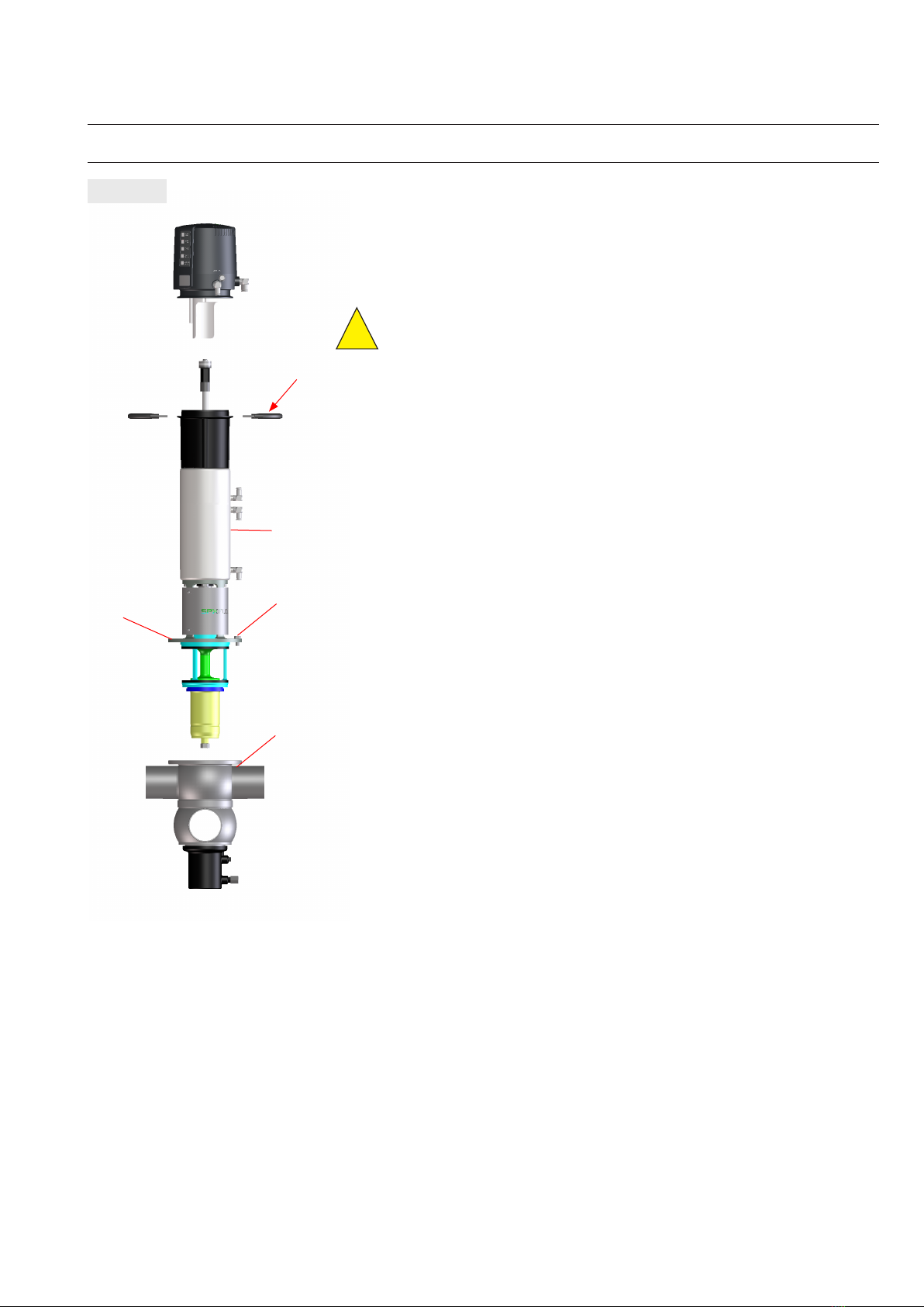
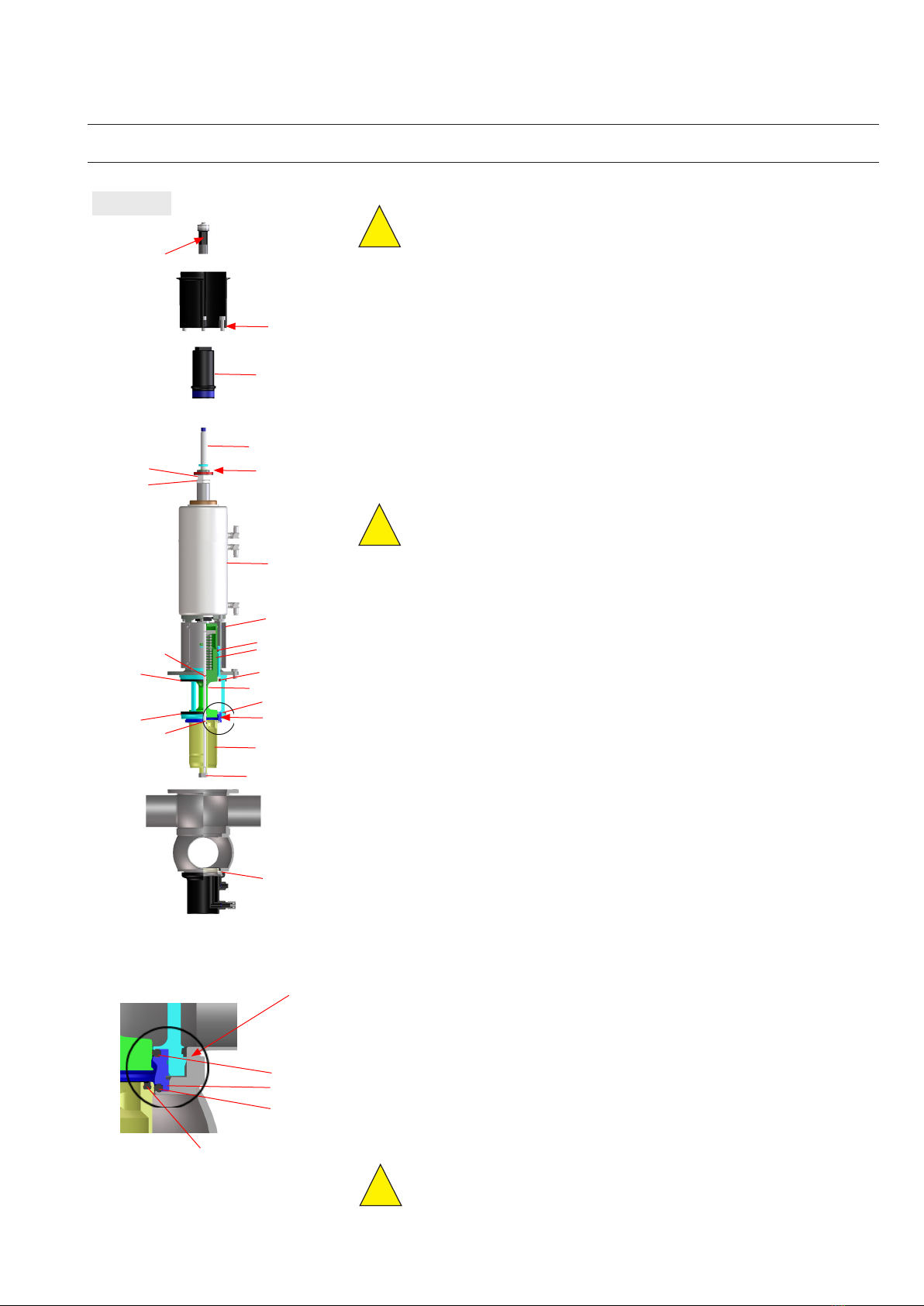
SPX FLOW Waukesha Cherry-Burrell DA4 User manual


This manual suits for next models
2
Other SPX FLOW Control Unit manuals

SPX FLOW
SPX FLOW W61 User manual

SPX FLOW
SPX FLOW APV DELTA UF3 User manual

SPX FLOW
SPX FLOW APV DELTA SDMS4 User manual

SPX FLOW
SPX FLOW Delair Etsiline CommPact User manual

SPX FLOW
SPX FLOW APV DELTA DE3 User manual

SPX FLOW
SPX FLOW APV DA4 User manual

SPX FLOW
SPX FLOW APV DELTA RGMS4 User manual

SPX FLOW
SPX FLOW WR60 Series User manual

SPX FLOW
SPX FLOW APV CU41-S User manual

SPX FLOW
SPX FLOW W70 Series User manual

SPX FLOW
SPX FLOW APV DELTA RGMS4 User manual

SPX FLOW
SPX FLOW Power Team A User manual

SPX FLOW
SPX FLOW APV DELTA DKR2 User manual

SPX FLOW
SPX FLOW APV DELTA RG4 User manual

SPX FLOW
SPX FLOW APV DELTA RG4 User manual

SPX FLOW
SPX FLOW APV DELTA SV1 User manual

SPX FLOW
SPX FLOW APV DELTA MS4 User manual
 User manual")
SPX FLOW
SPX FLOW APV DELTA UF3(A) User manual

SPX FLOW
SPX FLOW W71 User manual

SPX FLOW
SPX FLOW APV DELTA CPV User manual


Popular Control Unit manuals by other brands

Faderfox
Faderfox MX 12 user manual

Pilz
Pilz PSSu E AI SHT2 operating manual

Nortek
Nortek tvone CM-HDBT-2OUT-1ETH quick start guide

UUGear
UUGear Witty Pi 3 user manual

Telit Wireless Solutions
Telit Wireless Solutions NE866B1 Hardware Design Guide

Glas-Col
Glas-Col PLSM Series Operating and safety instructions

Comelit
Comelit Simplebus1 Ultra UT1020 Technical manual

EMC
EMC VNXe3300 Replacing

GEM
GEM N086 Installation, Operating and Maintenance Instructions for the Installer and the User

Skipper
Skipper DB-100-SA Installation and operation manual

Danfoss
Danfoss SVA-DH Instructions for use

ALLEN & HEATH
ALLEN & HEATH Qu-24 reference guide


