CG Emotron VS30401P3 Guide

Emotron VS10 / VS30 AC drive
0.25 … 2.2 kW
Mounting and switch on instruction

This page intentionally left blank!

3
Contents
Contents
1General information................................................................................................................................ 4
1.1 First read, then start ...................................................................................................................4
1.2 Notations and conventions.........................................................................................................4
2Safety instructions ..................................................................................................................................5
2.1 Basic safety measures.................................................................................................................5
2.2 Residual hazards .........................................................................................................................6
2.3 Application as directed ...............................................................................................................6
3 Product description ........................................................................................................................... 7
4 Mounting ...........................................................................................................................8
4.1 Important notes..........................................................................................................................8
4.2 Mechanical installation
Dimensions VS10/VS30 - 0.25 kW ... 0.37 kW ......................................9
4.3 Electrical installation.................................................................................................................12
4.3.1.1 Fusing and terminal data ..........................................................................................................13
4.3.2.1 Fusing and terminal data ..........................................................................................................15
4.3.3 3-phase mains connection 400 V ..............................................................................................16
4.3.3.1 Fusing and terminal datas.........................................................................................................17
4.3.4 Connection to the IT system .....................................................................................................18
4.3.5 CANopen/Modbus connection .................................................................................................19
4.3.5.1 Connection plan........................................................................................................................19
4.3.5.2 Terminal data............................................................................................................................19
5Commissioning...................................................................................................................................... 20
5.1Important notes........................................................................................................................21
5.2Before initial switch-on.............................................................................................................20
5.3Initial switch-on / functional test with terminal control ...........................................................21
6Technical data ....................................................................................................................................... 23
6.1 Standards and operating conditions .........................................................................................23
6.2 1-phase mains connection 230/240 V.......................................................................................25
6.3 1/3-phase mains connection 230/240 V ...................................................................................26
6.3.1 Rated data ................................................................................................................................26
6.4 3-phase mains connection 400 V ..............................................................................................27

4
1 General information
First read, then start
1General information
1.1 First read, then start
Read this documentation thoroughly before carrying out the installation andcommissioning.
▶Please observe the safety instructions!
1.2 Notations and conventions
1.2.1 Product code, examples:
VS10-23-1P7-20-CM
VS10-40-1P7-20-CM
VS
10
23
1P7
20
CM
Series
1-phase
230V
Rated current 1.7A
IP20
CANopen & Modbus
VS
30
40
1P7
20
CM
Series
3-phase
400V
Rated current 1.7A
IP20
CANopen & Modbus
Information
and tools with regard to the Emotron products can be found on the Internet:
http://www.emotron.com/services-support/file-archive/
WARNING!

5
Safety instructions 2
Basic safety measures
2Safety instructions
2.1 Basic safety measures
Disregarding the following basic safety measures may lead to severe personal injury and damage to material
assets!
The product
• must only be used as directed.
• must never be commissioned if they display signs of damage.
• must never be technically modified.
• must never be commissioned if they are not fully mounted.
• must never be operated without required covers.
Connect/disconnect all pluggable terminals only in deenergised condition.
Only remove the product from the installation in the deenergisedstate.
Insulation resistance tests between 24V control potential and PE: According to EN 61800−5−1, the maximum
test voltage must not exceed 110 VDC.
Observe all specifications of the corresponding documentation supplied. This is the precondition forsafe
and trouble-free operation and for obtaining the product features specified.
The procedural notes and circuit details described in this document are only proposals. It is up to the user to
check whether they can be adapted to the particular applications. Emotron does not take any responsibility
for the suitability of the procedures and circuit proposals described.
The product must only be used by qualified personnel. IEC 60364 or CENELEC HD 384 define the skills of
these persons:
• They are familiar with installing, mounting, commissioning, and operating the product.
• They have the corresponding qualifications for their work.
• They know and can apply all regulations for the prevention of accidents, directives, and lawsapplicable
at the place of use.
Observe the specific notes in the other chapters!

6
2 Safety instructions
Residual hazards
2.2 Residual hazards
The user must take the residual hazards mentioned into consideration in the risk assessment for his/her
machine/system.
If the above is disregarded, this can lead to severe injuries to persons and damage to material assets!
Product
Observe the warning labels on the product!
Icon
Description
Electrostatic sensitive devices:
Before working on the inverter, the staff must ensure to be free of electrostatic charge!
Dangerous electrical voltage
Before working on the inverter, check whether all power connections are dead! After mains OFF, power con-
nections X100 and X105 carry a dangerous electrical voltage for the time specified on the inverter!
High leakage current:
Carry out fixed installation and PE connection in compliance with EN 61800−5−1 or EN 60204−1 !
Hot surface:
Use personal protective equipment or wait until devices have cooleddown!
Motor
If there is a short circuit of two power transistors, a residual movement of up to 180°/number of pole pairs
can occur at the motor! (For 4-pole motor: residual movement max. 180°/2 =90°).
This residual movement must be taken into consideration by the user for his/her risk assessment.
2.3 Application as directed
The product
• must only be operated under the operating conditions prescribed in this documentation.
• meets the protection requirements of 2014/35/EU: Low-Voltage Directive.
• is not a machine in terms of 2006/42/EC: Machinery Directive.
• is not a household appliance, but is only designed as component for commercial or professional usein
terms of EN 61000−3−2.

7
Product description 3
3Product description
IT screw
Network X2xx
CANopen/Modbus(Option)
Toggle switch
CANopen/Modbus
Shield connection
Control connection
Motor connection X105
IT screw
Interface X16
Diagnostic Module
Inverter status LEDs
Earth/ground connection (PE)
Shield connection
CANopen/Modbus
Relay output X9
Mains voltage connection X100
Control terminals X3
Basic I/O
Memory module X20

8
4
Mounting
Important notes
4Mounting
4.1 Important notes
Dangerous electrical voltage
Possible consequence: death or severe injuries
▶All works on the inverter must only be carried out in the deenergised state.
▶After switching off the mains voltage, wait for at least 3 minutes before you start working.
DANGER!

9
Mounting
Mechanical
installation
4
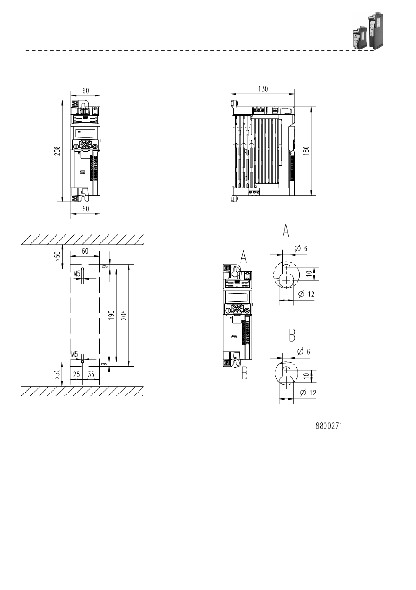
4.2 Mechanical installation
Dimensions
VS10/VS30 - 0.25 kW ... 0.37 kW
All dimensions in mm
10
4
Mounting
Mechanical installation
Dimensions VS10/VS30 - 0.55 kW ... 0.75 kW
All dimensions in mm

11
Mounting
Mechanical
installation
4
Dimensions VS30 - 1.1 kW ... 2.2 kW
All dimensions in mm

12
4
Mounting
4.3 Electrical installation
4.3.1 1-phase mains connection 230/240 V
The wiring diagram is valid for I5xAExxxBinverters.
Fig. 1: Wiring example
S1 Run/Stop
Fx Fuses
Q1 Mains contactor
--- Dashed line =options
100
mA
ϑ
ϑ
F1
Q1
L
L
L1
L2
3
N
PE
3/N/PE
AC
400
V
L1
L2
3
N
PE
3/N/PE
AC
208
V
...
240
V
L1
L2
N
PE
2/N/PE
AC
208
V
...
240
V
1/N/PE
A
C
170
V
...
264
V
45
Hz
...
65
Hz
F1
…
F2
Q1
2/PE
A
C
170
V
...
264
V
45
Hz
...
65
Hz
F1
…
F3
Q1
2/PE
A
C
170
V
...
264
V
45
Hz
...
65
Hz
+
+
CANopen/Modbus
+
Modbus
AC 240 V
3 A
Basic I/O
+24 V
+10 V
S1
M
+
3~
X105
U
V
W
X100
L1
L2/N
X3
GND
AI1
AI2
AO1
10V
24V
DI1
DI2
DI3
DI4
DI5
DO1
GND
0
...
10
V
1k
...
10k
4.4k
4.4k
X100
L1
L2/N
4.4k
4.4k
4.4k

13
Mounting
Electrical
installation
Connection
to the 230 V system
4
4.3.1.1 Fusing and terminal data
Inverter
VS30401P3
VS30401P8
VS30402P4
VS30403P2
VS30403P9
VS30405P6
VS30401P3
Cable installation in
compliance with
EN 60204-1
Laying system
B2
Operation
without mains choke
Fuse
Characteristic
gG/gL or gRL
Max. rated current
A
10
10
16
16
25
25
25
Circuit breaker
Characteristic
B
Max. rated current
A
10
10
16
16
25
25
25
Operation
with mains choke
Fuse
Characteristic
gG/gL or gRL
Max. rated current
A
10
10
16
16
25
25
25
Circuit breaker
Characteristic
B
Max. rated current
A
10
10
16
16
25
25
25
Earth-leakage circuit
breaker
≥ 30 mA, type A or B
Mains connection
Connection
X100
Connection type
Screw terminal
Min. cable cross-section
mm²
1
Max. cable cross-section
mm²
2.5
6
Stripping length
mm
8
Tightening torque
Nm
0.5
0.7
Required tool
0.5 x 3.0
0.6 x 3.5
Motor connection
Connection
X105
Connection type
Screw terminal
Min. cable cross-section
mm²
1
Max. cable cross-section
mm²
2.5
Stripping length
mm
8
Tightening torque
Nm
0.5
Required tool
0.5 x 3.0
PE connection
Connection
PE
Connection type
PE screw
Min. cable cross-section
mm²
1
Max. cable cross-section
mm²
6
Stripping length
mm
10
Tightening torque
Nm
1.2
Required tool
0.8 x 5.5

14
4
Mounting
Electrical
installation
Connection
to the 230 V system
4.3.2- 1/3-phase mains connection 230/240V
The wiring diagram is valid for Emotron VS10/VS30inverters.
Emotron VS10/VS30 inverters do not have an integrated EMC filter in the AC mains
supply.
In order to comply with the EMC requirements according to EN 61800−3, an
external EMC filter
according to IEC EN 60939 has to be used.
The user must prove that the EN 61800−3 requirements for conformity are fulfilled.
Fig. 2: Wiring example S1 Run/Stop
Fx Fuses
Q1 Mains contactor
--- Dashed line = Options
F1
Q1
L1
L2
L3
N
PE
3/N/PE
AC
400
V
L1
L2
L3
N
PE
3/N/PE
AC
208
V
...
240
V
F1
…
1/N
/PE
F2
A
C
170
V
...
264
V
Q1
45
Hz
...
65
Hz
2/PE
AC
170
V
...
264
V
45
Hz
...
65
Hz
F1
…
F3
Q1
3/PE
A
C
170
V
...
264
V
45
Hz
...
65
Hz
+
+
CANopen/Modbus
+
Modbus
AC 240 V
3 A
Basic I/O
+24 V
+10
V
100
mA
S1
ϑ
ϑ
M
+
3~
X105
U
V
W
X100
L1
L2/N
L3
X3
GND
AI1
AI2
AO1
10V
24V
DI1
DI2
DI3
DI4
DI5
DO1
GND
0
...
10
V
1k
...
10k
4.4k
4.4k
X100
L1
L2/N
L3
4.4k
4.4k
4.4k

15
Mounting
Electrical
installation
Connection
to the 230 V system
4
4.3.2.1 Fusing and terminal data
Inverter
VS30401P3
VS30401P8
VS30402P4
VS30403P2
VS30403P9
VS30405P6
VS30401P3
Cable installation in
compliance with
EN 60204-1
Laying system
B2
Operation
without mains choke
Fuse
Characteristic
gG/gL or gRL
Max. rated current
A
10
10
16
16
25
25
25
Circuit breaker
Characteristic
B
Max. rated current
A
10
10
16
16
25
25
25
Operation
with mains choke
Fuse
Characteristic
gG/gL or gRL
Max. rated current
A
10
10
16
16
25
25
25
Circuit breaker
Characteristic
B
Max. rated current
A
10
10
16
16
25
25
25
Earth-leakage circuit
breaker
≥ 30 mA, type A or B
≥ 30 mA, type B
Mains connection
Connection
X100
Connection type
Screw terminal
Min. cable cross-section
mm²
1
Max. cable cross-section
mm²
2.5
6
Stripping length
mm
8
Tightening torque
Nm
0.5
0.7
Required tool
0.5 x 3.0
0.6 x 3.5
Motor connection
Connection
X105
Connection type
Screw terminal
Min. cable cross-section
mm²
1
Max. cable cross-section
mm²
2.5
Stripping length
mm
8
Tightening torque
Nm
0.5
Required tool
0.5 x 3.0
PE connection
Connection
PE
Connection type
PE screw
Min. cable cross-section
mm²
1
Max. cable cross-section
mm²
6
Stripping length
mm
10
Tightening torque
Nm
1.2
Required tool
0.8 x 5.5

16
4
Mounting
Electrical
installation
Connection
to the 230 V system
4.3.3 3-phase mains connection 400 V
The wiring diagram is valid for I5xAExxxFinverters.
Fig. 3: Wiring example
S1 Run/Stop
Fx Fuses
Q1 Mains contactor
--- Dashed line = o tions
100
mA
ϑ
ϑ
L
L1
L2
3
N
PE
3/N/PE
AC
400
V
F1
…
F3
Q1
3/PE
A
C
340
V
...
528
V
45
Hz
...
65
Hz
CANopen/Modbus
+
Modbus
AC 240 V
3 A
Basic I/O
+24 V
+10 V
S1
M
+
3~
X105
U
V
W
X3
GND
AI1
AI2
AO1
10V
24V
DI1
DI2
DI3
DI4
DI5
DO1
GND
0
...
10
V
1k
...
10k
4.4k
4.4k
4.4k
4.4k
4.4k

17
Mounting
Electrical
installation
Connection
to the 400 V system
4
4.3.3.1 Fusing and terminal datas
Inverter
VS30401P3
VS30401P8
VS30402P4
VS30403P2
VS30403P9
VS30405P6
Cable installation in
compliance with
EN 60204-1
Laying system
B2
Operation
without mains choke
Fuse
Characteristic
gG/gL or gRL
Max. rated current
A
10
10
10
16
16
16
Circuit breaker
Characteristic
B
Max. rated current
A
10
10
10
16
16
16
Operation
with mains choke
Fuse
Characteristic
gG/gL or gRL
Max. rated current
A
10
10
10
16
16
16
Circuit breaker
Characteristic
B
Max. rated current
A
10
10
10
16
16
16
Earth-leakage circuit
breaker
≥ 30 mA, type B
Mains connection
Connection
X100
Connection type
Screw terminal
Min. cable cross-section
mm²
1
Max. cable cross-section
mm²
2.5
Stripping length
mm
8
Tightening torque
Nm
0.5
Required tool
0.5 x 3.0
Motor connection
Connection
X105
Connection type
Screw terminal
Min. cable cross-section
mm²
1
Max. cable cross-section
mm²
2.5
Stripping length
mm
8
Tightening torque
Nm
0.5
Required tool
0.5 x 3.0
PE connection
Connection
PE
Connection type
PE screw
Min. cable cross-section
mm²
1
Max. cable cross-section
mm²
6
Stripping length
mm
10
Tightening torque
Nm
1.2
Required tool
0.8 x 5.5

18
4
Mounting
Electrical
installation
Connection
to the IT system
4.3.4 Connection to the IT system
Internal components have earth/ground potential if the IT screws are not removed.
Consequence: the monitoring functions of the IT system respond.
▶Before connection to an IT system be absolutely sure to remove the IT screws.
VS10231P7, VS10232P4,
VS30401P3,
VS10233P2, VS10234P2, VS10236P0, VS10237P0,
VS10239P6,
VS30401P8, VS30402P4, VS30403P2, VS30403P9,
VS30405P6,
TX10
NOTICE!
TX10
TX10

19
Mounting
Electrical
installation
CANopen/Modbus
connection
4
4.3.5 CANopen/Modbus connection
4.3.5.1 Connection plan
Fig. 3: Wiring example: CANopen or Modbus network
4.3.5.2 Terminal data
Terminal description
CANopen/Modbus
Connection
X216
Connection type
Spring terminal
Min. cable cross-section
mm²
0.5
Max. cable cross-section
mm²
1.5
Stripping length
mm
10
Tightening torque
Nm
-
Required tool
0.4 x 2.5
4.3.5.3 Basic network settings
Configuring network basic settings
1. Use toggle switch on front of the inverter to select CANopen or Modbus network.
2. Set node address and baud rate via corresponding parameters.
The network must be terminated with a 120 Ω resistor at the physically
first
and last node.
Connect resistor to terminals CH/TA and CL/TB.
120
A1
A2
A3
An
X216
X216
X216
X216
120
CH/
TA
CL/
TB
CG/
COM
CH/
TA
CL/
TB
CG/
COM
CH/
TA
CL/
TB
CG/
COM
CH/
TA
CL/
TB
CG/
COM

20
5
Commissioning
Important notes
5Commissioning
5.1 Important notes
Incorrect settings during commissioning may cause unexpected and dangerous motor and system
movements.
Possible consequence: death, severe injuries or damage toproperty
▶Clear hazardous area.
▶Observe safety instructions and safetyclearances.
5.2 Before initial switch-on
Prevent injury to persons and damage to property. Check the following before switching on the mains
voltage:
• Is the wiring complete and correct?
• Are there no short circuits and earth faults?
• Is the motor circuit configuration (star/delta) adapted to the output voltage of the inverter?
• Is the motor connected in-phase (direction of rotation)?
• Does the "emergency stop" function of the entire plant operate correctly?
WARNING!
This manual suits for next models
14
Table of contents
Other CG DC Drive manuals


Popular DC Drive manuals by other brands


Trane
Trane Liquid-Cooled Adaptive Frequency AFDE Installation, operation and maintenance

hager
hager h250 HXC04 H Series User instructions

Toshiba
Toshiba TOSVERT VF-PS1 instruction manual

GE
GE AV-300i user guide

Zurik
Zurik ZRK-EMLV2-30W-XXDC user guide

SEW-Eurodrive
SEW-Eurodrive MOVIMOT MM..D Series Compact operating instructions


