CGC RFG50CF User manual
Page: 1/23 RFG50CF, Rev.3-15
Radio Frequency Generator for Driving
Electrodynamic Multipoles
Version 3-15CF
User Manual
Document version A, created on Apr-04-2023
CGC Instruments Tel.: +49 (371) 355 098–55
Hübschmannstr. 18
|
D
–
09112 Chemnitz Fax: +49
(
371
)
355 098
–
60 internet: www.cgc-instruments.com
e
–
mail: info
@
c
g
c-instruments.com

Page: 2/23 RFG50CF, Rev.3-15
Contents
Safety Information ..........................................................4
Technical Data................................................................5
Characteristics .............................................................................. 5
Mains Supply................................................................................. 5
RF Power Supply.......................................................................... 5
RF Output...................................................................................... 5
Security......................................................................................... 5
Fan Control ................................................................................... 6
Bias Voltage.................................................................................. 6
Monitoring ..................................................................................... 6
Device State.................................................................................. 6
General ......................................................................................... 6
Shipment Contents........................................................................ 7
Quick Setup Guide .........................................................8
Description ...................................................................10
General ....................................................................................... 10
Device Function .......................................................................... 11
Terminals .................................................................................... 13
Installation And Operation............................................16
Troubleshooting............................................................19
References:..................................................................23
CGC Instruments Tel.: +49 (371) 355 098–55
Hübschmannstr. 18
|
D
–
09112 Chemnitz Fax: +49
(
371
)
355 098
–
60 internet: www.cgc-instruments.com
e
–
mail: info
@
c
g
c-instruments.com

Page: 3/23 RFG50CF, Rev.3-15
Figure List
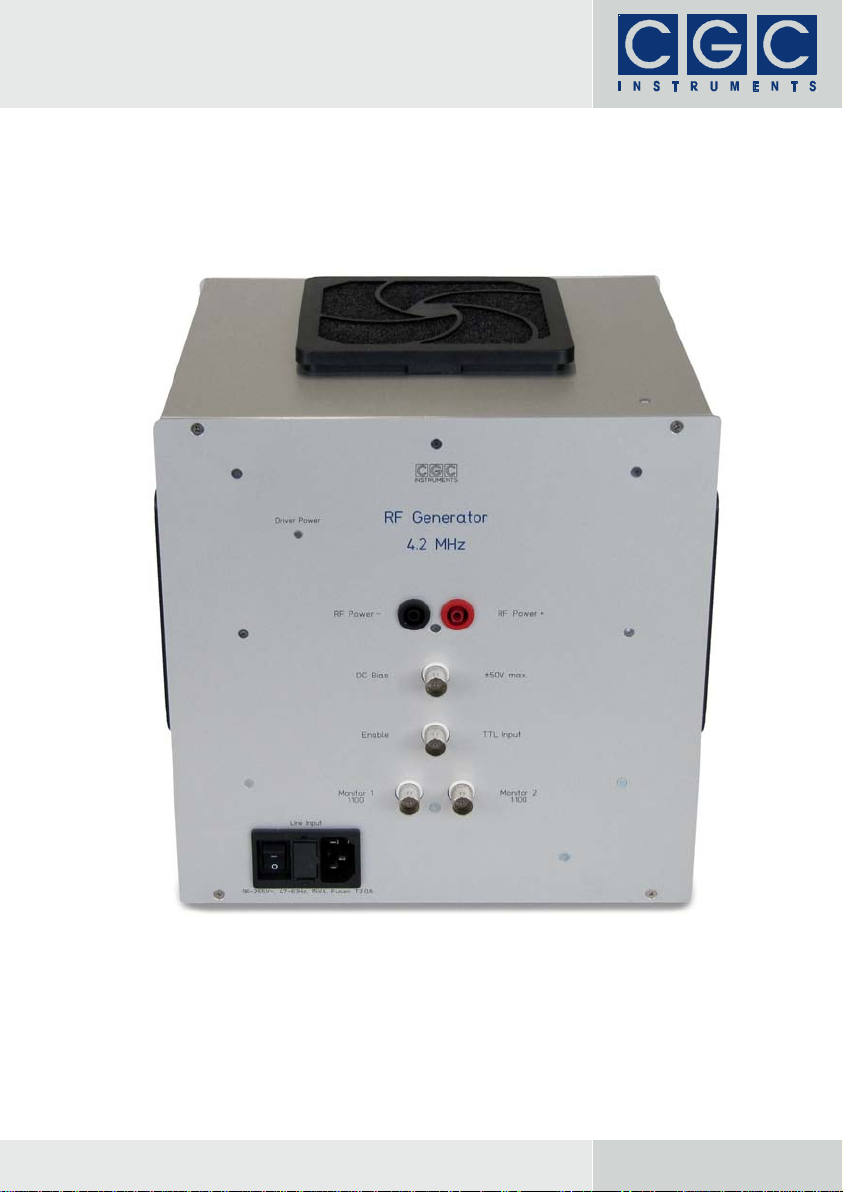
Fig. 1. The front panel of the RF generator. ............................... 10
Fig. 2. Simplified circuit diagram of the generator. ..................... 11
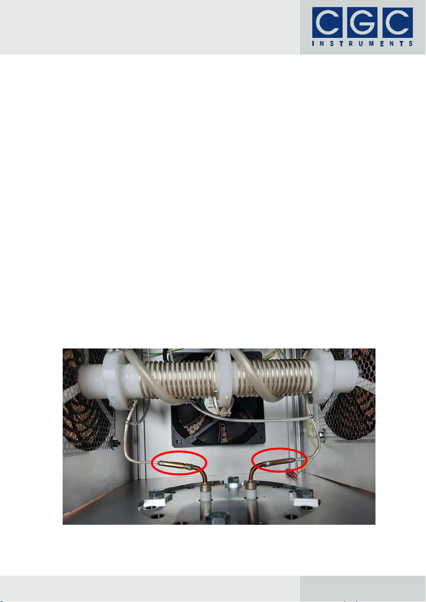
Fig. 3. View of the generator's RF terminals and the vacuum
flange DN100CF with the electrical feedthroughs............ 16
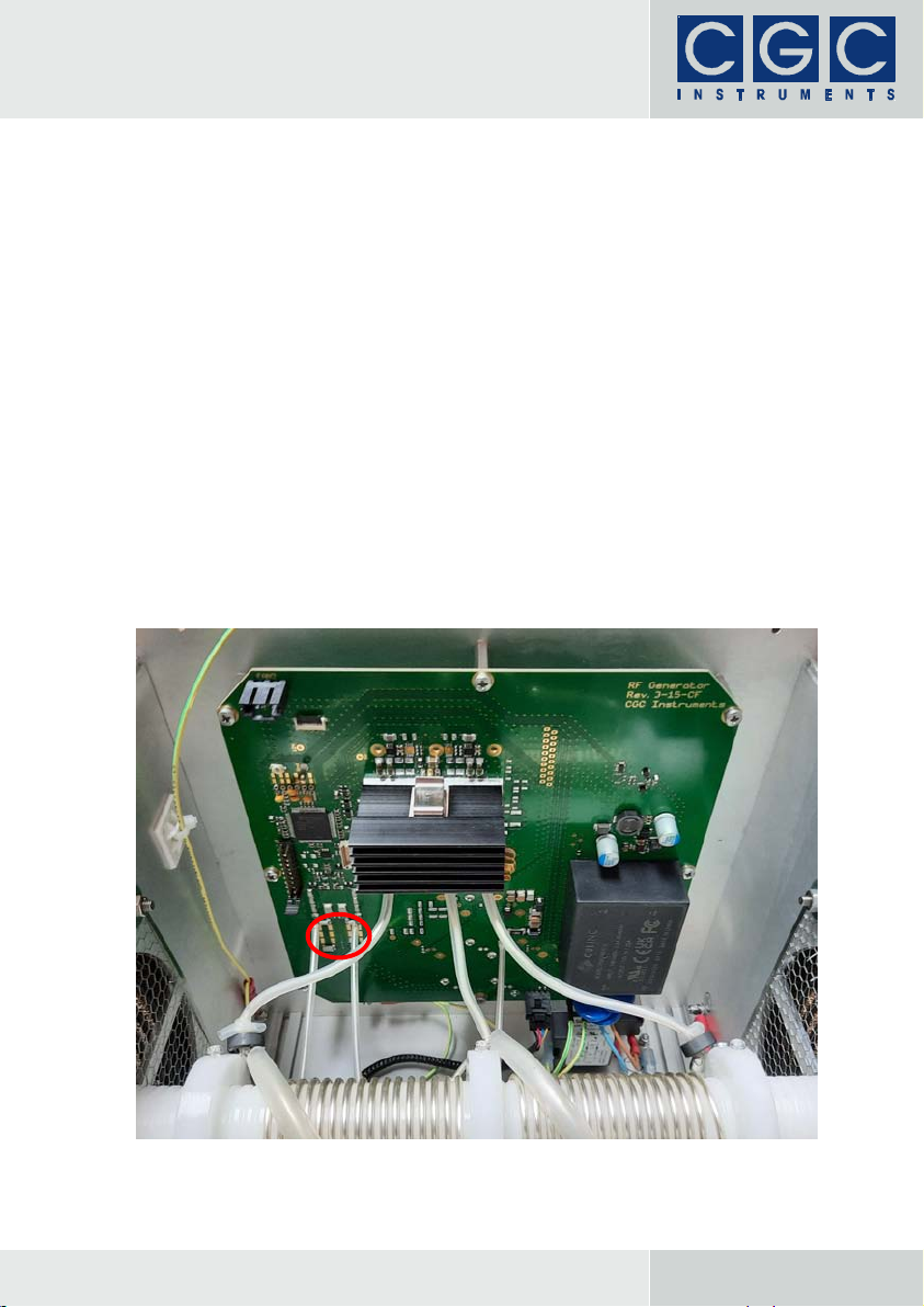
Fig. 4. View of the generator's printed circuit board. .................. 19
CGC Instruments Tel.: +49 (371) 355 098–55
Hübschmannstr. 18
|
D
–
09112 Chemnitz Fax: +49
(
371
)
355 098
–
60 internet: www.cgc-instruments.com
e
–
mail: info
@
c
g
c-instruments.com

Page:4/23 User Manual RFG50CF, Rev.3-15: Safety Information
Safety Information
• The device may be installed and used by authorized and instructed
personnel only. Read this manual carefully before installing and us-
ing the device. Always follow the safety notes and warnings in this
manual.
• The device is designed for indoor dry laboratory use only. Before
powering the device on, it must acclimatize to the ambient tempera-
ture to avoid moisture condensation. This is especially relevant after
transport.
• Do not operate the device if it is damaged or not functioning prop-
erly. Never use damaged cables or accessories.
• To avoid damage, connect the line cord to a properly wired and
grounded receptacle only. Be sure that the mains voltage and the
fuse rating match the device specification. Never operate the device
during thunderstorms.
• Never use corrosive or abrasive cleaning agents or polishes, avoid
the use of organic solvents. If necessary, clean the device with a
soft damp cloth. Make sure that the device is completely dry and
free from contaminants before powering it on.
!Warning: The radio frequency generator is an electronic device that is
sensitive to electrostatic electricity. While handling the generator, the
ESD (electrostatic discharge) protection rules must be kept in mind.
CGC Instruments Tel.: +49 (371) 355 098–55
Hübschmannstr. 18
|
D
–
09112 Chemnitz Fax: +49
(
371
)
355 098
–
60 internet: www.cgc-instruments.com
e
–
mail: info
@
c
g
c-instruments.com

Page:5/23 User Manual RFG50CF, Rev.3-15: Technical Data
Technical Data
Characteristics
• compact radio frequency (RF) generator
• symmetrical output voltage with DC bias
• digital enable control
• analog RF voltage control
• metallic case for DN100CF flange mount
• two fans and two air outlets for optimal forced cooling
Mains Supply
• universal line input: 90 – 255 V, 47 – 63 Hz
• power consumption:
standby (generator deactivated): <5 VA, 3.5 VA typ.
operation (RF enabled): <10 VA, 5 VA typ.
maximum (fan maximum): <15 VA, 10 VA typ.
• main fuses: T 2.0 A (slow acting, size ø5x20 mm)
• mains connection (Line Input):
IEC inlet with EMC filter and integrated fuse holder
RF Power Supply
• connectors: two banana safety sockets (RF Power +/–)
• voltage: 0 – 50 V typical, see test protocol
• current consumption: < 2 A typ., see test protocol
RF Output
• two electrical feedthroughs on the DN100CF flange
• frequency: given by the resonance frequency of the output circuitry,
see test protocol
• amplitude: continuously variable by the power supply voltage,
see test protocol
Security
• interlock loop (Enable):
BNC socket ot the front panel
signal level: TTL, internal pull-up to +5 V: 20 kΩ
polarity: short circuit disables the generator
CGC Instruments Tel.: +49 (371) 355 098–55
Hübschmannstr. 18
|
D
–
09112 Chemnitz Fax: +49
(
371
)
355 098
–
60 internet: www.cgc-instruments.com
e
–
mail: info
@
c
g
c-instruments.com

Page:6/23 User Manual RFG50CF, Rev.3-15: Technical Data
• over- and undertemperature protection:
temperature sensor at generator's heat sink
overtemperature threshold: +60°C
undertemperature threshold: +10°C
Fan Control
• linear temperature regulation
• minimum speed: below +30°C
• maximum speed: above +55°C
Bias Voltage
• connector: BNC socket (DC Bias)
• allowable voltage range: ±50 V typ., see test protocol
• internal serial resistance: 10 kΩtyp., see test protocol
Monitoring
• connectors: two BNC sockets (Monitor 1, Monitor 2)
• type: capacitive voltage divider
• output capacitance: 5 nF typ.
• attenuation: 1:100 typ.
Device State
• indicator: multicolor LED (Driver Power)
• color coding:
standby (disabled): yellow
active: green
overtemperature: red
undertemperature: blue
fan failure: cyan
General
• metallic case:
height and width: 239.5 mm, depth: 226.5 mm
total height with air filters: 260.5 mm
total width with air filters: 257.5 mm
outer surfaces: clear anodized, inner surfaces: chromated
CGC Instruments Tel.: +49 (371) 355 098–55
Hübschmannstr. 18
|
D
–
09112 Chemnitz Fax: +49
(
371
)
355 098
–
60 internet: www.cgc-instruments.com
e
–
mail: info
@
c
g
c-instruments.com

Page:7/23 User Manual RFG50CF, Rev.3-15: Technical Data
• forced cooling:
two 120 mm fans with air filters on the top and bottom panels
two 120 mm air outlets with air filters on the side panels
temperature-dependent control
monitored fan operation, warning in the event of a fan failure
• allowable temperature range for device operation: +10...+40°C
• weight: 6.4 kg typ. (incl. flange), see test protocol
• cleaning: use damp cloth only, avoid use of organic solvents
Shipment Contents
• radio frequency generator RFG50CF
• flange DN100CF with two electrical feedthroughs
• set of capacitors for frequency adjustment
• line cord (universal IEC mains lead, length 1.8 m)
• user manual in electronic form
CGC Instruments Tel.: +49 (371) 355 098–55
Hübschmannstr. 18
|
D
–
09112 Chemnitz Fax: +49
(
371
)
355 098
–
60 internet: www.cgc-instruments.com
e
–
mail: info
@
c
g
c-instruments.com

Page:8/23 User Manual RFG50CF, Rev.3-15: Quick Setup Guide
Quick Setup Guide
!Warning: The generator can produce lethal voltages, please note the
following before powering it on:
• The device must be properly grounded before the mains voltage is
applied. The device is intended to be mounted on a flange of a vac-
uum apparatus and grounded to it. Check the ground resistance in
case of any doubts.
• The output circuit must be connected by short wires with sufficiently
low impedance, please do not neglect skin effect. The generator
produces high-amplitude, high-frequency voltages. If not properly
connected and grounded, it may cause RF emissions with a high in-
tensity that may interfere with other devices. Thin output wires with a
high inductance will not provide a sufficient connection between the
output transformer and the load. This may lead to high-frequency
oscillations at the transformer output accompanied by high-
amplitude voltage peaks at the MOSFETs of the power stage. This
may limit the amplitude of the output voltage or even damage the
power stage.
• The device has been adjusted to the frequency and load specified
by the customer. For the exact test conditions, see the test protocol
provided with the device. When the device is put into operation,
compare the supply values with the test protocol and do not proceed
if there is a significant difference.
Connect the mains to the IEC inlet Line Input on the front panel (see
Fig. 1) via a standard line cord with the universal IEC mains lead. Turn
the device on via the switch integrated into the IEC inlet. The LED in-
dicator Driver Power should change color several times and, after the
startup sequence finishes, it should light up green — this indicates
that the device is enabled. Short the BNC socket Enable with a 50 Ω
terminator or apply a logical 0 to the input in another way. The LED
indicator should change to yellow, indicating that the generator is dis-
abled.
!Warning: If the LED indicator has any other color, see the section
"Technical Data" for an explanation of the indicated states and consult
the section "Troubleshooting". Do not proceed until the failure has
been resolved.
If the device works as expected, turn it off again and disconnect it
from the mains. Mount it to the flange and connect the electrodes to
CGC Instruments Tel.: +49 (371) 355 098–55
Hübschmannstr. 18
|
D
–
09112 Chemnitz Fax: +49
(
371
)
355 098
–
60 internet: www.cgc-instruments.com
e
–
mail: info
@
c
g
c-instruments.com

Page:9/23 User Manual RFG50CF, Rev.3-15: Quick Setup Guide
the outputs. Short the BNC socket DC Bias with a 50 Ωterminator,
connect the mains and turn the device on. Open the short circuit at the
BNC socket Enable and verify that the LED Driver Power lights up
green. Connect the DC power supply unit to the banana safety sock-
ets RF Power + and RF Power –, paying attention to the polarity.
!Warning: If a DC voltage with a wrong polarity is connected, the gen-
erator will limit the voltage to less than 1 V and will consume as much
current as the current limit of the DC power supply unit allows. Be
sure to initially set a low current limit to prevent an overload in case of
an error.
Connect an oscilloscope to the BNC sockets Monitor 1 and Monitor 2
via two short (no longer than 1 m) coaxial cables. Increase the voltage
of the DC power supply unit slowly and observe the output signals
with the oscilloscope. Compare the values with the data from the test
protocol.
!Warning: Every time the DC power supply unit is operated, its current
limit should be set to a value only slightly larger than the expected cur-
rent value from the test certificate. A good strategy is to set the de-
sired voltage and then increase the current limit until the set voltage is
reached. If the current consumption is significantly higher than ex-
pected, do not proceed and consult the section "Troubleshooting".
CGC Instruments Tel.: +49 (371) 355 098–55
Hübschmannstr. 18
|
D
–
09112 Chemnitz Fax: +49
(
371
)
355 098
–
60 internet: www.cgc-instruments.com
e
–
mail: info
@
c
g
c-instruments.com

Page:10/23 User Manual RFG50CF, Rev.3-15: Description
Description
General
The device is a radio frequency (RF) generator with an external power
supply unit for its power stage. It produces two harmonic signals
phase-shifted by 180°. It is self-tuning, i.e. it automatically runs at the
optimum working frequency close to the resonance frequency of the
output circuitry. A temperature sensor monitors the temperature of the
power semiconductors and shuts down the device if a critical tempera-
ture is reached. The device is fit into an approximately cube-shaped
metallic box (edge length about 23 cm). The front panel is shown in
Fig. 1. The front panel of the RF generator.
CGC Instruments Tel.: +49 (371) 355 098–55
Hübschmannstr. 18
|
D
–
09112 Chemnitz Fax: +49
(
371
)
355 098
–
60 internet: www.cgc-instruments.com
e
–
mail: info
@
c
g
c-instruments.com

Page:11/23 User Manual RFG50CF, Rev.3-15: Description
Fig. 1.
Device Function
The design of the device is based on the concept from reference [1],
but the circuit diagram has been significantly improved to obtain better
parameters and stable RF signals. This third generation of the RF
generators uses a field programmable gate array (FPGA) to integrate
all control and supervision functionality. The FPGA makes it possible
to implement a sophisticated device control and reach optimal pa-
rameters under any conditions.
The sinusoidal output voltages are produced by an RF transformer
(TR in Fig. 2). Its secondary winding acts as a resonance circuit to-
gether with the capacitance at the output leads RF1 and RF2. The de-
vice excites oscillations in this circuit at a frequency close to the elec-
trical resonance. The operation close to the electrical resonance fre-
quency and the symmetric circuit design provide sinusoidal output
voltages with a high amplitude and an excellent spectral purity.
Together with the inductance of the secondary winding of the trans-
former TR, the capacitance at the output leads RF1 and RF2 sets the
resonance frequency. Therefore, it indirectly determines the output
Fig. 2. Simplified circuit diagram of the generator.
CGC Instruments Tel.: +49 (371) 355 098–55
Hübschmannstr. 18
|
D
–
09112 Chemnitz Fax: +49
(
371
)
355 098
–
60 internet: www.cgc-instruments.com
e
–
mail: info
@
c
g
c-instruments.com

Page:12/23 User Manual RFG50CF, Rev.3-15: Description
frequency. The capacitance consists of the capacitance of the exter-
nal load including the connection cable and of the internal capaci-
tance. The latter is made up of the capacitors Co1/2and Ca1/2as
well as the capacitance of the transformer TR and the internal stray
capacitance. The capacitors Co1/2are adjusted in the factory to ob-
tain the desired output frequency. The user may exchange them if the
connected electrodes have a different capacitance than expected or if
the electrode hardware has been changed and/or the operating fre-
quency differs from the desired value. Consult the section
"Troubleshooting" for more details.
The input connector DC (BNC socket DC Bias on the front panel, see
Fig. 1) defines the DC potential of the RF output leads RF1 and RF2.
The DC voltage is applied to the outputs via the coil Ldc and the sec-
ondary winding of the transformer TR. The capacitors Cdc1 and Cdc2
together with the coil Ldc filter the RF signal from the transformer so
that only a small residual RF amplitude is present at the DC input DC.
The diode D1 provides overvoltage protection of the DC input. It limits
the DC voltage so that the connected capacitors cannot be over-
loaded even if the DC input is disconnected and electron or ion cur-
rents charge the electrodes connected to the outputs RF1 and RF2.
Note that in the real circuit, the coil Ldc is a serial combination of a coil
and a resistor, both result in the typical serial resistance of 10 kΩ(see
section "Technical Data").
The control unit (Controller in Fig. 2) of the device is based on an
FPGA. It senses the RF voltages via the capacitors Cs1 and Cs2 and
produces the control signals for the drivers Drv1 and Drv2 that drive
the gates of the MOSFETs Q1 and Q2. The MOSFETs form a push-
pull class E RF end stage, i.e. they operate with so-called soft switch-
ing (activating the MOSFETs in the time periods where no significant
drain voltage is present) to reduce switching losses. The primary cir-
cuitry contains the capacitors Cd1 and Cd2 as well as the inductors
Ld1 and Ld2, they optimize the signal waveforms at the MOSFET
drains and enable the soft switching.
The voltage for supplying the power stage is applied externally to the
terminals +V and –V (banana safety sockets RF Power + and
RF Power – on the front panel, see Fig. 1). The voltage is filtered by
the filter Fsup and the capacitors Cf1 and Cf2. The magnitude of the
applied voltage determines the output amplitude. For detailed informa-
tion about the conversion ratio and the current consumption, see the
test protocol of the specific device.
CGC Instruments Tel.: +49 (371) 355 098–55
Hübschmannstr. 18
|
D
–
09112 Chemnitz Fax: +49
(
371
)
355 098
–
60 internet: www.cgc-instruments.com
e
–
mail: info
@
c
g
c-instruments.com

Page:13/23 User Manual RFG50CF, Rev.3-15: Description
The device monitors the temperature of the heat sink onto which the
MOSFETs are mounted via the sensor T-Sens. If the measured tem-
perature exceeds a certain value, the device is disabled to prevent
additional heating. The device is also disabled if the temperature is
too low and moisture condensation can occur.
The device is equipped with an enable input Enb (BNC socket Enable
on the front panel, see Fig. 1) that accepts TTL levels. It can be used
to turn off the RF if, for instance, the connected ion trap has to be
emptied or if the vacuum pressure is not sufficiently low to safely op-
erate the connected electrodes. The input is equipped with an internal
pull-up resistor to +5 V of 20 kΩ, i.e. if the terminal is left open, the re-
sistor sets a logical 1 at the input that enables the device. If the termi-
nal is shorted — either directly or by a 50 Ωterminator — the device is
disabled by the resulting logical 0 at the input. Note that if the device
is disabled, the oscillations in the output circuitry do not stop immedi-
ately but their amplitude decreases exponentially. The duration of the
ringing at the output is given by the electrical quality of the output cir-
cuitry and may take many tens of periods. Similarly, the RF voltage
does not start up instantly and several RF periods are typically re-
quired to reach the desired amplitude.
To check the RF output voltages, two monitor outputs Mon1 and
Mon2 (BNC sockets Monitor 1 and Monitor 2 on the front panel, see
Fig. 1) are available. Their voltages are gained by passive capacitive
filters formed by the capacitors Ca1/2and Cb1/2. The attenuation ra-
tio is given by the ratios Cax/Cbx, the typical value is 1:100. The out-
put capacitance is given by the capacitors Cb1 and Cb2, the typical
values are 5–10 nF. The resistors Rb1 and Rb2 with a typical resis-
tance of 10 MΩset the DC component at the monitor outputs to zero
and prevent accidental charging of the terminals. The monitor circuitry
and the used component values make it possible to connect an oscil-
loscope to the monitor outputs via conventional coaxial cables without
losing the precision. A typical 1 m long coaxial cable has a capaci-
tance of about 100 pF, this causes a systematic error of only 1–2%.
Terminals
For the mains connection, an IEC inlet Line Input (see Fig. 1) with an
EMC filter and integrated fuse holder and switch is located on the front
panel. Use a standard line cord with the universal IEC mains lead to
connect the device to the mains. To replace the fuse, remove the line
CGC Instruments Tel.: +49 (371) 355 098–55
Hübschmannstr. 18
|
D
–
09112 Chemnitz Fax: +49
(
371
)
355 098
–
60 internet: www.cgc-instruments.com
e
–
mail: info
@
c
g
c-instruments.com

Page:14/23 User Manual RFG50CF, Rev.3-15: Description
cord and open the fuse holder. Insert the new fuse(s), close the fuse
holder, and connect the line cord back to the IEC inlet.
For supplying the power stage, i.e. for adjusting the output amplitude,
an adjustable DC power supply unit should be connected to the ba-
nana safety sockets RF Power + and RF Power –. Consult the test
certificate of the device to look up the voltage and current values re-
quired to achieve the desired RF amplitude. Note that if the device is
disabled or not powered on, the current consumption of the power
stage is almost zero, it usually does not exceed 1 mA. Therefore, it is
safe to apply the external DC power supply to the power stage even if
the device is turned off.
!Warning: Use a DC power supply unit with an adjustable current limit
and set it to a value only minimally larger (not more than +20%) than
the current value specified in the test certificate. If the current con-
sumption is larger than expected, check the output signals with an os-
cilloscope. The most likely cause is a wrong connection of the elec-
trodes, or their capacitance is different to the value the device was ad-
justed for in the factory. Consult the section "Troubleshooting" for
more details. If the output signals have the expected form, i.e. they
have a sinusoidal shape and the frequency matches the nominal
value, try to increase the current limit. However, values 20% larger or
more are suspect and the distributor or the manufacturer should be
contacted for further instructions if the reason cannot be identified.
The terminal DC Bias is a BNC socket to which an external DC volt-
age can be applied. This voltage determines the DC component of the
RF output signals and usually sets the potential on the axis of the
connected ion trap or ion guide. The input can be shorted by a 50 Ω
terminator if no DC voltage is applied. The input should not be left
open since ion or electron currents to the connected electrodes can
charge them and lead to unpredictable DC potentials. However, even
under these conditions, operating the device is still safe since the in-
put is equipped with an overvoltage protection (diode D1 in Fig. 2) that
prevents that the DC voltage from reaching voltages that could dam-
age the used components.
The terminal Enable is a BNC socket that can be used to enable or
disable the RF output. If it is left open or if a logic level 1 is applied,
the device is enabled and harmonic signals are generated on the RF
outputs. If the terminal is shorted or if a logic level 0 is applied, the de-
CGC Instruments Tel.: +49 (371) 355 098–55
Hübschmannstr. 18
|
D
–
09112 Chemnitz Fax: +49
(
371
)
355 098
–
60 internet: www.cgc-instruments.com
e
–
mail: info
@
c
g
c-instruments.com

Page:15/23 User Manual RFG50CF, Rev.3-15: Description
vice is disabled and no RF is generated. Note that a common 50 Ω
BNC terminator can be used for shorting.
The terminals Monitor 1 and Monitor 2 are BNC sockets that provide
output signals attenuated by the specified ratio. The typical attenua-
tion is 1:100, an oscilloscope can be connected directly via conven-
tional 50 Ωcoaxial cables. The cable length should not exceed 1 m,
otherwise a systematic error of several % will be introduced into the
monitoring signals.
The RF outputs are connected directly to the electrical feedthroughs
on the vacuum flange DN100CF onto which the device is mounted.
The connection can be disassembled if the generator needs to be re-
moved from the flange (see Fig. 3), e.g. if the vacuum chamber should
be baked out at temperatures higher than about 100°C.
CGC Instruments Tel.: +49 (371) 355 098–55
Hübschmannstr. 18
|
D
–
09112 Chemnitz Fax: +49
(
371
)
355 098
–
60 internet: www.cgc-instruments.com
e
–
mail: info
@
c
g
c-instruments.com
Page:16/23 User Manual RFG50CF, Rev.3-15: Installation And Operation
Installation And Operation
!Before powering on the device, read the user manual thoroughly.
The device is intended to be mounted on a flange of a vacuum appa-
ratus. It requires a space of at least 27 × 27 × 30 cm³ (width × height ×
depth). The installation space must be kept dry and the temperature
and humidity within the range specified in the section "Technical Da-
ta". Note that, depending on the amplitude of the output voltage, the
device produces heat during operation. Avoid exposing the device to
direct sunlight since this may significantly increase the device tem-
perature. High device temperatures may lead to increased noise from
the running fans or even a thermal shutdown if the heat sink ap-
proaches the shutdown temperature (see section "Technical Data").
Ensure that the vacuum apparatus can carry the weight of the genera-
tor specified in the test protocol.
During operation, only the front panel of the RF generator has to be
accessible. The device can operate in any position; however, the air
inlets on the top and bottom panels as well as the air outlets on the
side panels must not be covered or obstructed. They must have ac-
cess to sufficiently cool air for active cooling of the device. Inspect and
clean the air filters regularly. Furthermore, use a vacuum cleaner to
Fig. 3. View of the generator's RF terminals and the vacuum flange DN100CF with the
electrical feedthroughs.
The red circles mark the output terminals.
CGC Instruments Tel.: +49 (371) 355 098–55
Hübschmannstr. 18
|
D
–
09112 Chemnitz Fax: +49
(
371
)
355 098
–
60 internet: www.cgc-instruments.com
e
–
mail: info
@
c
g
c-instruments.com

Page:17/23 User Manual RFG50CF, Rev.3-15: Installation And Operation
remove dust from the filters and the fans in the device housing. Large
dust layers substantially lower the cooling power (the device may
overheat if the air filters are extremely dirty). The lifetime of dirty fans
can also be significantly shorter.
If the RF generator was shipped with a mounted vacuum flange and
connected RF terminals (see Fig. 3), the flange must be removed prior
to the installation of the device. To gain access to the flange and the
terminals, the device cover plate has to be removed: Unfasten the four
M3 screws that hold the cover plate in place (two on the front and two
on the rear panel) and remove it. The cover plate with the mounted
fan is connected to the device with a grounding wire and the fan ca-
ble, it can only be completely removed if both cables are discon-
nected.
Carefully open the connectors connecting the RF outputs to the elec-
trical feedthroughs on the vacuum flange (see red circles in Fig. 3).
!Make sure that only the silver-coated wires and not the electrical
feedthroughs are mechanically stressed.
!Do not touch the silver-coated wires or the chromated inner surfaces
of the device case with bare fingers since the coating will be chemi-
cally affected and lose its high electric conductivity.
Unfasten the four M8 screws fixing the vacuum flange to the rear plate
and remove the flange. Mount it to the vacuum apparatus with the
gasket of choice. Be sure to insert only the remaining 12 screws and
leave the four screws for fixing the generator unused. Mount the gen-
erator case to the vacuum flange and tighten all its 16 screws.
Connect the RF outputs to the electrical feedthroughs on the vacuum
flange, do not mechanically stress them. Connect the cables of the
cover plate (the grounding wire and the fan cable) to the device. At-
tach the cover plate to the case and tighten the four M3 screws.
Connect the electrodes to the vacuum side of the electrical feed-
throughs. Use thick silver-coated round or flat wires to minimize the
skin effect and reduce losses. Keep the capacitance of the wires
against ground and against each other low by keeping the spacing as
large as possible. Use sufficiently large clamps to connect the wires to
the electrical feedthroughs. Note that all parts of the output circuitry
have to conduct large RF currents, often several Amps or even more
than 10 A. Depending on the operating frequency, such currents re-
CGC Instruments Tel.: +49 (371) 355 098–55
Hübschmannstr. 18
|
D
–
09112 Chemnitz Fax: +49
(
371
)
355 098
–
60 internet: www.cgc-instruments.com
e
–
mail: info
@
c
g
c-instruments.com

Page:18/23 User Manual RFG50CF, Rev.3-15: Installation And Operation
quire conductors with a large surface to minimize losses and prevent
heating by the RF.
To power the device, a power mains socket with proper grounding is
required. Check the voltage rating on the front panel before connect-
ing the line cord and powering on the device.
!Warning: Supplying the device with a voltage outside the specifica-
tion may permanently damage the device.
Follow the instructions in the section "Quick Setup Guide". Consult the
remaining parts of the manual if the device behaves differently to this
description. Should that not resolve the problem, contact the distribu-
tor or the manufacturer.
CGC Instruments Tel.: +49 (371) 355 098–55
Hübschmannstr. 18
|
D
–
09112 Chemnitz Fax: +49
(
371
)
355 098
–
60 internet: www.cgc-instruments.com
e
–
mail: info
@
c
g
c-instruments.com
Page:19/23 User Manual RFG50CF, Rev.3-15: Troubleshooting
Troubleshooting
If the LED indicator Driver Power does not light up, check the line
connection and the fuses integrated in the IEC inlet Line Input on the
front panel (see Fig. 1). If the fuses are broken, check the voltage rat-
ing of the device and the applied line voltage. If the failure occurs
again, contact the distributor or the manufacturer.
If the LED indicator Driver Power does not light up green or yellow,
but a different color is displayed, this indicates that either the device
has overheated (red), the device temperature is too low (blue), or one
of the fans is not running properly (cyan, see section "Technical
Data"). In case of an over- or undertemperature, let the device accli-
matize to the room temperature. Also make sure that the room tem-
perature is within the allowable range (see section "Technical Data").
In case of a fan failure, the generator should not be operated since the
cooling may not be sufficient. Locate the defective fan and remove the
Fig. 4. View of the generator's printed circuit board.
The red circle marks the capacitors Co1 and Co2 for adjusting the resonance frequency
of the output circuit.
CGC Instruments Tel.: +49 (371) 355 098–55
Hübschmannstr. 18
|
D
–
09112 Chemnitz Fax: +49
(
371
)
355 098
–
60 internet: www.cgc-instruments.com
e
–
mail: info
@
c
g
c-instruments.com

Page:20/23 User Manual RFG50CF, Rev.3-15: Troubleshooting
respective cover plate. The fans are mounted on the top and bottom
cover plates which can be removed by unfastening the four M3
screws fixing the respective plate (two on the front and two on the rear
panel). The cover plate can then be detached and the fan replaced.
Contact the distributor or the manufacturer for information on how to
obtain the replacement parts.
If the operating frequency differs from the desired value, if the output
signals do not have a sinusoidal waveform or are not symmetric, or if
the current consumption is larger than expected, i.e. the current con-
sumption does not correspond to the data from the test protocol, the
output circuitry has to be checked and/or the output capacitance has
to be adjusted.
The most likely cause for strongly asymmetric output signals is a short
circuit in the output circuitry. Discharges can also result in asymmetric
signals, they can further degrade the signal shape and limit the ampli-
tude. The typical symptom is a strongly increasing current consump-
tion at higher amplitudes.
If the device does not operate at the desired frequency or if the output
signals show a small asymmetry, the most likely cause is a wrong
output capacitance. The output capacitance consists of the capaci-
tance of the external load (the electrode system, including the connec-
tion wires or cables), the internal capacitance from the capacitors
Co1/2and Ca1/2, as well as the internal capacitance of the RF gen-
erator. The capacitors Co1 and Co2 (see Fig. 4) are adjusted for the
desired output frequency in the factory. Check the test protocol for the
set values.
!In case of any discrepancy between the observed supply voltage and
current and the values given in the test protocol, be extremely careful
when increasing the supply voltage of the power stage. If the genera-
tor does not behave similarly to the data in the test protocol, the load
capacitance is most probably incorrect and the device may easily be
overloaded. If the device is operated at higher supply voltages of the
output power stage and consumes excessive current to reach a cer-
tain output amplitude, it may be permanently damaged. Be sure not to
exceed a supply power of 10–20 W in order to prevent any damage if
the device does not behave according to the test protocol.
The resonance frequency of an LC circuit is given by the following
equation:
CGC Instruments Tel.: +49 (371) 355 098–55
Hübschmannstr. 18
|
D
–
09112 Chemnitz Fax: +49
(
371
)
355 098
–
60 internet: www.cgc-instruments.com
e
–
mail: info
@
c
g
c-instruments.com
Table of contents


