Tradinco TRAQC-8 User manual

User Manual
TRAQC-8
TRAQC-8
Portable Calibrator
User Manual

User Manual
TRAQC-8
TRAQC-8 04/2017 EN Rev.4 page : 2
Content
1. General ...............................................................................................5
1.1 Warranty .........................................................................................5
1.2 TRAQC-8 Description.........................................................................6
1.2.1 CE Pressure Equipment Directive 2014/68/EU ..................................6
1.2.2 CE EMC Directive 2014/30/EU ........................................................6
1.2.3 CE Electrical Safety Directive 2014/35/EU........................................7
1.3 Symbols Used ..................................................................................7
1.4 Scope of this manual ........................................................................7
1.5 Calibrator Interface...........................................................................8
1.6 Navigation .......................................................................................9
1.7 Electrical Connections .....................................................................10
2. Operating Instructions ........................................................................11
2.1 Set up...........................................................................................11
2.2 Operating Instructions ....................................................................11
2.2.1 Measurement of external test pressures ........................................12
2.3 Instructions for the refilling of the gas bottles ....................................12
2.4 End of use .....................................................................................12
2.5 Storage .........................................................................................12
2.6 Power Supply.................................................................................13
2.6.1 Battery status display .................................................................13
2.6.2 Operating time indication.............................................................13
2.6.3 Instrument charging before storage ..............................................13
2.6.4 Battery Replacement...................................................................13
2.7 Power On/Off .................................................................................14
2.8 Menu ............................................................................................14
2.9 Zeroing .........................................................................................15
2.10 Selecting Pressure Units ..................................................................15
2.11 Pressure Range ..............................................................................16
2.11.1 Electric in- or output active.........................................................16
2.11.2 Electric in- or output not active ...................................................16
2.11.3 Selecting Pressure sensor Auto ranging .........................................16
2.12 Instrument Status ..........................................................................17
3. User Configuration..............................................................................18
3.1 Pressure Setup...............................................................................18
3.1.1 Pressure range ...........................................................................18
3.1.2 Pressure unit..............................................................................18
3.1.3 Averaging on/off.........................................................................18
3.1.4 Averaging setup .........................................................................18
3.1.5 Resolution Setup ........................................................................19
3.1.6 Conversion Table ........................................................................19
3.1.7 Set customer unit .......................................................................19
3.1.8 Absolute mode ...........................................................................20
3.2 Electrical Input A Setup...................................................................20
3.2.1 mA Input...................................................................................20
3.2.2 mA + Xmtr Supply (optional) .......................................................21
3.2.3 Xmtr Power Setup (optional)........................................................21
3.2.4 Resistance input (optional) ..........................................................21
3.2.5 RTD input (optional) ...................................................................21
3.2.6 Switch Test................................................................................22
3.2.7 Switch Test Setup.......................................................................22
3.2.8 V Input......................................................................................22
3.2.9 Hart Resistor..............................................................................22
3.2.10 mA/V Scaling .............................................................................22
3.2.11 Set mA/V Scaling.......................................................................23
23
3.3 Electrical Output A Setup (optional) ..................................................24

User Manual
TRAQC-8
TRAQC-8 04/2017 EN Rev.4 page : 3
3.3.1 Pressure xmtr mode (Pressure transmitter mode)...........................24
3.3.2 Xmtr mode settings (Parameter Mode Settings)..............................25
3.3.3 Current Output...........................................................................25
3.3.4 Current Output Settings ..............................................................25
3.3.5 Voltage Output...........................................................................26
3.3.6 Voltage Output Settings ..............................................................26
3.3.7 Auto Span Check Mode................................................................26
3.3.8 Ramp Mode ...............................................................................26
3.4 Electrical input B setup (optional) .....................................................26
3.5 Electrical output B setup (optional) ...................................................26
3.6 Instrument Configuration ................................................................27
3.7 Using the Memory Mode ..................................................................29
3.8 Memory Functions ..........................................................................29
3.8.1 List by tag number .....................................................................29
3.8.2 List by serialnumber ...................................................................29
3.8.3 View definitions ..........................................................................29
3.9 Advanced Options...........................................................................30
3.9.1 Set rtc time ...............................................................................30
3.9.2 Set rtc date ...............................................................................30
3.9.3 Set recal Date ............................................................................30
3.9.4 Erase data memory.....................................................................30
3.9.5 Show Product Data .....................................................................31
3.10 Calibration of TRAQC-8....................................................................32
3.10.1 Adjust instrument inputs. ............................................................32
3.10.1.1 Current input ....................................................................... 33
3.10.1.2 Current in + Loop supply (optional) ....................................... 33
3.10.1.3 Voltage input ....................................................................... 33
3.10.1.4 Adjust Vbat A/D ................................................................... 34
3.10.1.5 P1: XX-YY BARG (Pressure Sensor Adjustment)........................ 34
3.10.1.6 Clear user adjustments ......................................................... 34
3.10.1.7 Resistance input ................................................................... 34
3.10.2 Adjust instruments outputs (optional) ...........................................35
3.10.2.1 Current source ..................................................................... 35
3.10.2.2 Current simulator ................................................................. 35
3.10.2.3 Voltage output ..................................................................... 36
3.10.3 Show calibration factors ..............................................................36
4. Data transfer .....................................................................................37
5. Computer Interface (Optional) .............................................................37
5.1 General Description ........................................................................37
5.2 Connections...................................................................................37
5.3 RS232 Settings ..............................................................................37
6. Maintenance instructions .....................................................................38
6.1.1 Main power supply cable..............................................................38
6.1.2 Housing.....................................................................................38
6.1.3 Test connections.........................................................................38
6.1.4 Regulating valves .......................................................................38
6.2 Pressure gauges .............................................................................38
6.3 Battery maintenance.......................................................................39
6.4 High pressure gas bottles ................................................................39
7. Product Specifications .........................................................................40
7.1 General .........................................................................................40
7.2 Measurement .................................................................................40
7.3 Generation and control....................................................................40
7.4 Data storage..................................................................................40
7.5 Options & Accessories .....................................................................41


User Manual
TRAQC-8
TRAQC-8 04/2017 EN Rev.4 page : 5
1. General
1.1 Warranty
During the design and manufacturing of this instrument the at most attention has been given to
quality and durability.
This manual contains information needed for the safe and effective use of the
capabilities of the instrument.
Please read the manual carefully before operating the instrument. By doing so possible
damage to the instrument or damage caused by the incorrect use of the instrument can
be avoided.
TRADINCO INSTRUMENTS warrantees the instrument in accordance with the Standard Terms and
Conditions of the Instrument Trade as issued by the Association bearing the name "Federation
Het Instrument" (The Instrument Federation, (filed with the Clerk of Utrecht District Court on 13
January 1993 under number 16/93 and with the Chamber of Commerce and Industry in
Amersfoort on 18 January 1993. A copy is available on request.
TRADINCO INSTRUMENTS warrantees that this product will be free from defects in materials and
workmanship for a period of 5 years from the date of shipment. If any such product proves
defective during this warranty period, TRADINCO INSTRUMENTS, at its option, will either repair
the defective product without charge for parts or labour, or will provide a replacement in exchange
for the defective product.
In order to obtain service under this warranty, Customer must notify TRADINCO INSTRUMENTS
of the defect before the expiration of the warranty period and make suitable arrangements for
the performance of the service.
Customer shall be responsible for packaging and shipping of the defective product to the service
centre designated by TRADINCO INSTRUMENTS, with shipping charges prepaid.
If no defect can be found Customer may be charged for costs of the investigation.
This warranty does not apply to any defect, failure or damage caused by:
a. Improper use of the instrument.
b. Battery leakage.
c. Normal wear of the product.
d. Modification or repair carried out by or on behalf of the owner or by a third party.
e. Implementation of modifications to the product that are not supplied or implemented by
TRADINCO INSTRUMENTS.
TRADINCO INSTRUMENTS and its vendors will not be liable for any indirect, special, incidental or
consequential damages irrespective of whether TRADINCO INSTRUMENTS or the vendor has
advance notice of the possibility of such damages.
The type number of the product, as listed on the instrument tag plate, should always be
mentioned in any correspondence concerning the product.
Tradinco Instrumenten-Apparaten b.v.
Radonstraat 250
2718 TB Zoetermeer
The Netherlands
+31 79 2033133
www.tradinco.com
info@tradinco.com

User Manual
TRAQC-8
TRAQC-8 04/2017 EN Rev.4 page : 6
1.2 TRAQC-8 Description
The Tradinco Pneumatic Pressure Calibrator, TRAQC-8 is
a universal pressure calibrator, ranging from 0 to 250
bar.
The TRAQC-8 has been designed for the testing and
calibration of low and high pressure pneumatic
measurement equipment:
regulators, pressure gauges, pressure converters,
pressure switches, recorders, etc.
Because of the built-in rechargeable battery and high
pressure gas bottles it is possible to use this test unit at
location, independent of any external mains power
supply and/or pressure source.
The TRAQC-8 consists of 6 main parts.
•A high quality digital pressure display with curser and two function push buttons.
•One or more pressure sensors plus related pneumatic circuit.
•An electrical measuring circuit (standard mA + V DC)
•One high quality digital calibrator
•One pneumatic regulating system
•Two high pressure gas bottles
With the TRAQC-8 it is possible to measure test pressures generated by the built-in gas bottles
as well with test pressures which are generated by an external pressure source.
The aluminum case of the TRAQC-8 is provided with a lid which has a handle for carrying the
calibrator.
The test and filling hoses are stored in a case in the lid of the carrying case.
Dimensions are (LxWxH) 405x295x255 mm and the weight is approximately 17 kg.
1.2.1 CE Pressure Equipment Directive 2014/68/EU
The TRAQC-8 meets the safety regulations as mentioned in appendix 1 of the European
guideline 2014/68/EU.
The TRAQC-8 is a combination of different pressure component as mentioned in article 1
paragraph 2.1.5
The maximum volume of the biggest pressure bearing housing is 1 liter with a maximum
pressure of 200 bar.
TRAQC-8 classified to be used with gas group 2
Following table two the TRAQC-8 are manufactured in accordance with article 3 paragraph 3
"sound engineering practice" and CE marking based on the PED does not apply.
1.2.2 CE EMC Directive 2014/30/EU
The electrical part of the TRAQC-8 meets the regulations as mentioned standards
•EN-IEC 61000-4-2 : 2009
•EN-IEC 61000-4-3 : 2009
•EN-IEC 61000-4-4 : 2012
•EN-IEC 61000-4-5 : 2009
•EN-IEC 61000-3-2 : 2014
•EN-IEC 61000-3-3 : 2013
The unit is CE marked accordingly.
User Manual
TRAQC-8
TRAQC-8 04/2017 EN Rev.4 page : 7
1.2.3 CE Electrical Safety Directive 2014/35/EU
The electrical part of the TRAQC-8 (pressure calibrator of the Tradinco Traqc-7 series) meets
the regulations as mentioned standards
EN 61010-1 : 2010
•The unit is CE marked accordingly
1.3 Symbols Used
Warning for conditions or practices that could result in personal injury, loss of life and/or
in damage to the product or other property.
Attention signal or remark
1.4 Scope of this manual
This manual contains information for instruments built after Oktober 2015 with firmware revision
2.343 or higher.
This manual is a user manual on how to operate the instrument; it is not a calibration instruction
manual.
As Tradinco Instruments continuously strives to improve its products, specifications of
instruments may be altered without further notice.
User Manual
TRAQC-8
TRAQC-8 04/2017 EN Rev.4 page : 8
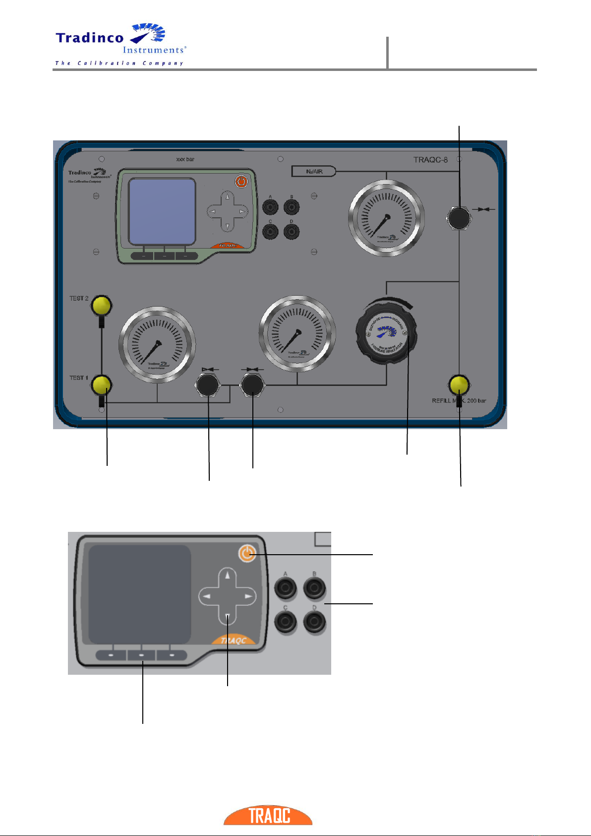
1.5 Calibrator Interface
Bottle shut off
valve
Test
connections
Relief (vent) valve
Supply valve
Pressure
control valve
(PCV)
Refill
connection
On / Off key
Electrical
connections
Navigation keys
Function keys (F1, F2, F3)

User Manual
TRAQC-8
TRAQC-8 04/2017 EN Rev.4 page : 9
1.6 Navigation
The menus can be accessed when the calibrator is in measuring mode.
Navigating through the menus is possible by pressing the function keys (F1, F2 and F3) and the
‘ARROW’keys. Above the function keys in the display the meaning of the keys is displayed. By
pressing the function keys below the desired field in the display, the menu opens.
Pressing the key below the field ‘EXIT’(under F3) results in going one level back. By pressing the
key below the field ‘ENTER’ (under F1) results in going one level further.
The menus consist of multiple options to choose from. The option in the black bar is the one
selected. By using the navigation keys another option in the menu is selected.
User Manual
TRAQC-8
TRAQC-8 04/2017 EN Rev.4 page : 10
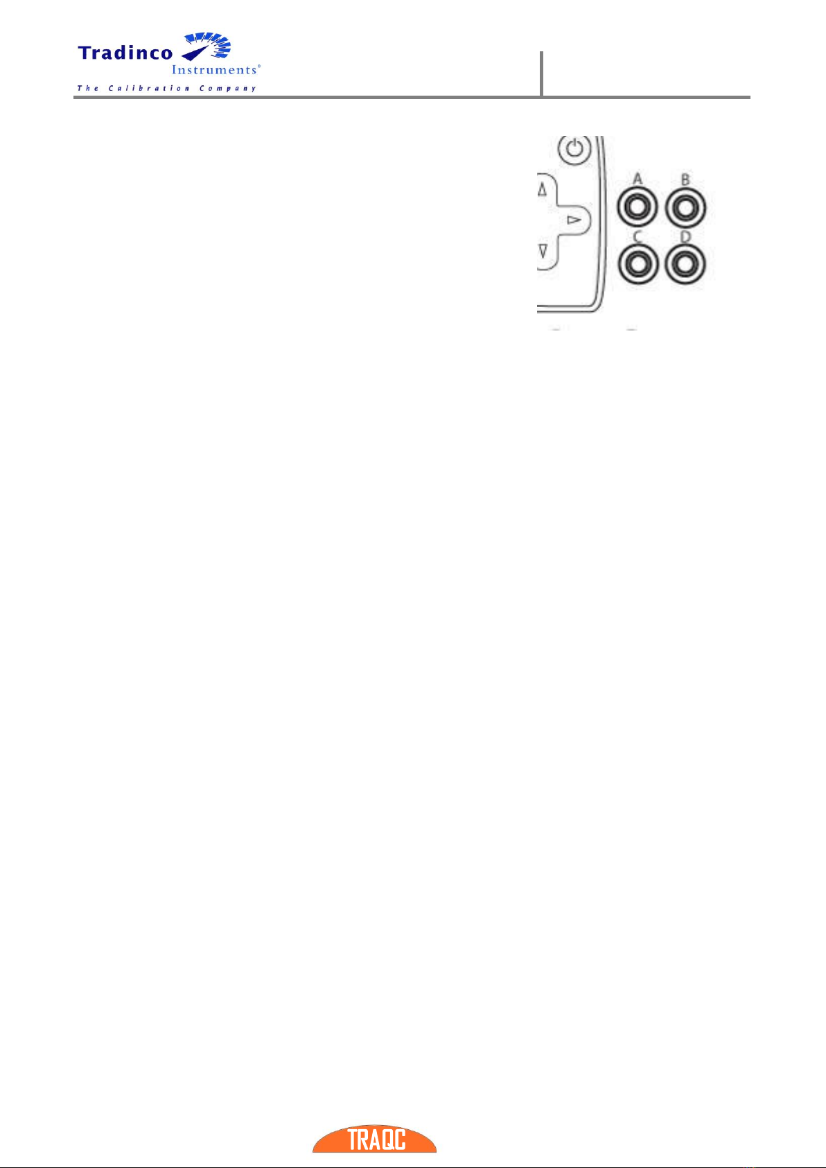
1.7 Electrical Connections
The “Electric Connections Layout” in the display references the
physical layout of these 4 banana socket. (Example see figure).
The letters A,B,C and D are for identification purposes and will
be of reference, in this manual only

User Manual
TRAQC-8
TRAQC-8 04/2017 EN Rev.4 page : 11
2.Operating Instructions
2.1 Set up
Place the unit on a stable table.
•Open the 4 (four) locks and take the lid of the case.
•Check the calibrator for damages.
•Plug the power supply cable in the right side of the unit.
•Control the power supply indication before plug in.
2.2 Operating Instructions
The TRAQC-8 is a pressure calibrator with a maximum of 200 bar and is design for a so-called
"dead end" system. The calibrator includes a high pressure reducer which has to be fed by an
external pressure source of maximal 200 bar or by the internal gas bottles. Depending on the
range of the pressure sensor which is mentioned on the front side of the TRAQC-8, the range of
the reducer is selected. On the pressure outlet of the reducer are a pressure shut off valve and
a bleed valve for fine adjustment of the test pressure.
•Close the “bottle shut off valve” by turning it fully clockwise.
•Decrease the “reducer” by turning it fully counterclockwise.
•Close the “pressure shut off valve” by turning it fully clockwise.
•Open the “bleed valve” by turning it fully counterclockwise.
•Connect the “test” coupling to the unit to be calibrated.
•Close the “bleed valve” and open both the “pressure shut off valve” and “bottle shut off
valve”.
•Slowly increase the pressure with the “reducer” until the maximum admissible pressure
for the unit under test is reached.
•Close the “pressure shut off valve”, close the “bottle shut off valve” and decrease the
“reducer” to minimum.
•Check with the TRAQC-8 if there is any leakage; this becomes apparent by an extreme
change of the test pressure.
•Remove the pressure from the system by opening the “bleed valve”(1).
•Eliminate any leaks and repeat the test as described above until all leaks are eliminated.
•Close the “bleed valve”.
•Open both the “bottle shut off valve” and “pressure shut off valve”.
•Increase the “reducer” to circa 110% of the desired test pressure. Than close the
“pressure shut off valve”.
•For regulating the test pressure:
-Slowly opening and closing the “pressure shut off valve” will result in a pressure
increase.
-Slowly opening and closing the “bleed valve” will result in a pressure decrease.
•A measurement can be performed when the “bottle shut of valve”, “pressure shut off
valve”, the “bleed valve” are all closed.
•Repeat the procedure as often as a new test pressure is desired. When all test pressures
have been generated repeat the following sequence for getting the system back to
atmospheric pressure:
-Close the “bottle shut off valve”
-Open the “bleed valve”
-Decrease the “reducer” to the minimum.
-Open the “pressure shut off valve”.
-Disconnect the test hoses
The valves have a soft seat and a tight shut-off. It is not necessary to close them with
excess force.

User Manual
TRAQC-8
TRAQC-8 04/2017 EN Rev.4 page : 12
2.2.1 Measurement of external test pressures
It is also possible to measure pressures generated by external systems. In this case the reducer
and the gas bottle will not be used. All control valves will have to be closed.
2.3 Instructions for the refilling of the gas bottles
The refilling of the gas bottles can be done by using either another bottle or a high pressure
compressor. The maximal refilling pressure is 200 and the capacity is 2 liters.
When the refilling is done from another bottle, the included RU 3 connector can be used.
The refilling by a high pressure compressor can be made by a direct connection.
•Close both the “bottle shut off valve” and the “pressure shut off valve”.
•Increase the “reducer” to a the maximum.
•Open the “bleed valve”.
•Connect the filling hose to the ‘refill connection’.
•Set the compressor or the external bottle to a maximum of 200 bar.
•Slowly open the “bottle shut off valve”. The gas bottle will be refilled and the
pressure of the bottle can be checked on the manometer.
•Slowly let the gas bottle be refilled. A quick refilling will increase the temperature.
An increase in temperature will affect the pressure by increasing it. This means no
optimal filling will be obtained.
•Close the gas ‘bottle shut off valve” and shut-off the compressor.
•To get the filling hose free of pressure, decrease the “reducer” to a minimum and
open the ‘Pressure shut off valve’
•Then disconnect the filling hose.
2.4 End of use
•Close the “bottle shut off valve”
•Open the “bleed valve”.
•Set the “reducer” to a minimum.
•Open the “pressure shut of valve”.
•Disconnect the unit under test from the unit.
•Disconnect the test hoses and put them in the carrying case in the lid of the 8185.
•Place the cover of the TRAQC-8 back on and close the four locks.
2.5 Storage
End the utilization of the TRAQC-8 as follows:
•Store it indoors, in a temperature between 0 and 60° Celsius.
•Decrease the “reducer” turning it fully anti clock wise
•Open both the “bleed valve” and the “pressure shut off valve”.
•Empty the internal gas bottles by slowly opening the “bottle shut off valve”.
•Place the cover of the 8185 back on and close the four locks.
•Place the case a horizontal position.
Equipment which has rechargeable batteries will need to be stored with fully charged batteries,
charging and discharging of batteries one every 3 months is advised.
When connected to the mains power a trickle charge will be maintained.

User Manual
TRAQC-8
TRAQC-8 04/2017 EN Rev.4 page : 13
2.6 Power Supply
The unit is equipped with an internal not removable Li-Ion battery. The charging of the batteries
is fully automated. The TRAQC-8 is charged when its connected to the mains power supply
charging will start as soon as the instrument is connected to the mains supply.
The instrument can be used while charging the battery, but the required charging time could be
increased depending upon the selected operating mode of the instrument.
2.6.1 Battery status display
The status of the battery is displayed with a battery symbol on the lcd display when the
instrument is switched on.
During charging the battery symbol will be filled with lines until it is completely filled and when
all lines are drawn the symbol will be cleared and starts filling again.
When charging is completed the symbol will be completely filled and remains filled as long as
the instrument is connected to the mains supply.
2.6.2 Operating time indication
The instrument has an internal ‘gas gauge’ to measure the battery capacity, this gas gauge is
automatically updated when the battery is charged or discharged and is used to indicate the
battery charging state and remaining operating time.
The charging state of the battery is indicated with lines in the battery symbol.
When the battery is full all lines in the battery are drawn and when the instrument is operating
on the battery less lines will be shown.
The number of lines shown in the battery is a rough indication of the remaining battery
capacity.
When the remaining operating time drops below 3 hours the remaining time will be shown next
to the battery symbol
The operating time of the instrument on the indicated charge state depends upon the
usage of the instrument, Operating modes where the electrical outputs are used draw
more current from the battery and therefore shorten the operating time more than other
modes.
2.6.3 Instrument charging before storage
The instrument should not be stored for longer periods with an empty battery, doing so will
reduce the capacity of the battery and shorten the battery life.
When the instrument must be stored the battery should be charged to at least 50% of its
indicated capacity.
2.6.4 Battery Replacement
The battery can only be replaced by Tradinco or a Tradinco approved repair facility.

User Manual
TRAQC-8
TRAQC-8 04/2017 EN Rev.4 page : 14
2.7 Power On/Off
The TRAQC-8 is switched on and off by pressing the on/off key. The TRAQC-8 will go through a
short startup self-check routine. During that routine the display shows the current firmware. After
completing the startup procedures the device switches into the measuring mode and displays the
measured value(s), and the measuring unit(s) from last time. When turning off the device, the
display shows ‘Shutting Down’.
If the calibrator needs to be recalibrated at short notice, a message with the date that the
instrument should be re-calibrated is displayed for several seconds before the startup
procedure continues. If the recalibration date has expired a message is displayed as a
warning. By pressing ‘ENTER’ key (F1) the start-up procedure is continued.
2.8 Menu
The main menu is accessed by pressing the ‘MENU’ key (F1). On
top in the display the current location in the menu structure is
shown.
Some of the functions in the menu structure are for
optional functionality of the instruments. Therefore it is
possible the TRAQC-8 included with this manual has less
functions than explained in this user manual.
Main Menu
pressure
setup
electric
input A
setup
electric
input B
setup
electric
output A
setup
electric
output B
setup
instrument
configuration
memory
functions
advanced
options
Pressure range
mA input
Under
development
pressure xmtr
mode
Under
development
backlight
setup
list by
tagnr.
Set rtc time
Pressure unit
mA + Xmtr
supply
xmtr mode
settings
select
language
list by
serialnr.
Set rtc date
Averaging
on/off
V input
mA source
output
date/time
display
view
definitions
Set recall
date
averaging setup
Resistance
input
mA simulator
output
show settings
Erase data
memory
resolution setup
RTD input
current output
settings
factory
defaults
Show
instrument
data
conversion table
Switch test
voltage output
Set IP address
Adjust
instrument
inputs
Set customer
unit
XMTR power
setup
voltage output
settings
Change PIN
code
Adjust
instrument
output
absolute mode
switch test
setup
auto span
check mode
Booster on
pressure
Show
calibration
factors
Hart resistor
Ramp mode
Booster on
differential
mA/V scaling
Set mA/V
scaling
User Manual
TRAQC-8
TRAQC-8 04/2017 EN Rev.4 page : 15
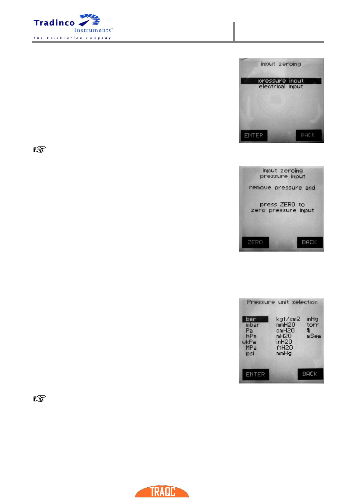
2.9 Zeroing
To zero an input signal press ‘ZERO’ key (F2) in the “measuring
mode” display. The menu shows the different inputs that can be
zeroed, consisting of pressure inputs and the electrical inputs.
Select the desired input using the ‘ARROW’ keys.
•By pressing the ‘BACK’ key (F3) the zeroing procedure is
stopped without making modifications.
•By pressing ‘ENTER’ key (F1) the zeroing procedure is
continued and there is asked to confirm the zeroing
procedure after which the calibrator returns to measuring
mode.
When zeroing the ‘Pressure Input’, ensure that the pressure ports are open to atmospheric
pressure.
The TRAQC-8 comes standard with a quick connect coupling with
integraded shut off valve. This can be opened by:
•Connect/insert the other half of the coupling to the pressure
coupling (-port) of the TRAQC-8
•Connect one side of a pressure hose to the pressure
coupling (-port) of the TRAQC-8 and leave the other side of
the hose unconnected.
With these procedures the pressure in the system of the TRAQC-8
can get equal with the atmospheric pressure.
To zero another test pressure and/or electrical signal, first generate
the required test signal (tare value) and carry out the above-
described zeroing procedure. The test value displayed is the difference between the actual test
value and the entered tare value.
2.10Selecting Pressure Units
When in “measuring mode” screen press the ‘UNIT’ key (F3) to change
the unit. Use the ‘ARROW’ keys to select the desired unit and press
‘ENTER’ key (F1) to confirm and go back to “measuring mode”.
The following units can be selected:
bar kgf/cm2inHg
mbar mmH2O torr
Pa cmH20 %
hPa mH2O mSeaw
kPa inH20
MPa ftH2O
psi mmHg
Not all operating modes that support pressure measurement have the ‘UNIT’ key due to lcd
and keyboard space limitations. The pressure unit can also be selected via the menu, press
the ‘F1’key and select the ‘pressure setup’ and then ‘pressure unit’ for these modes.
User Manual
TRAQC-8
TRAQC-8 04/2017 EN Rev.4 page : 16
2.11Pressure Range
Depending upon the configuration of the instrument the TRAQC-8 can be equipped with one,
two or three pressure sensors.
In instruments with two or three sensors the user can select the pressure range by pressing the
‘UP’-or ‘DOWN’, ‘ARROW’ key in “measuring mode”
Not all operating modes support the ‘UP’ or ‘DOWN’ keys for selecting the pressure
range. To change the pressure range you can also select the option ‘pressure range’ in
the ‘pressure setup’ menu.
Depending upon the operating mode the range selection menu offers different possibilities.
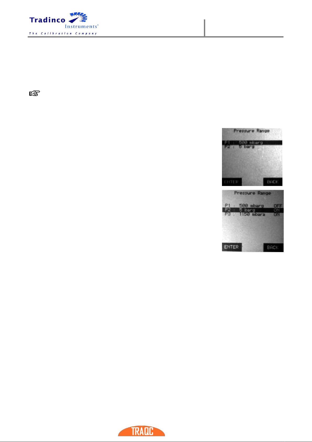
2.11.1 Electric in- or output active
When the instrument is also measuring an electrical signal only one
pressure input can be used. By using the ‘ARROW’ keys, select the
desired pressure sensor and press ‘ENTER’ key (F1) to confirm, press
the ‘BACK’ key (F3) to cancel.
2.11.2 Electric in- or output not active
When the electrical input are not active an instrument with more than
one sensor can show the measured value of two pressure inputs.
In this situation the pressure range menu can be used to switch the
individual ranges on or off.
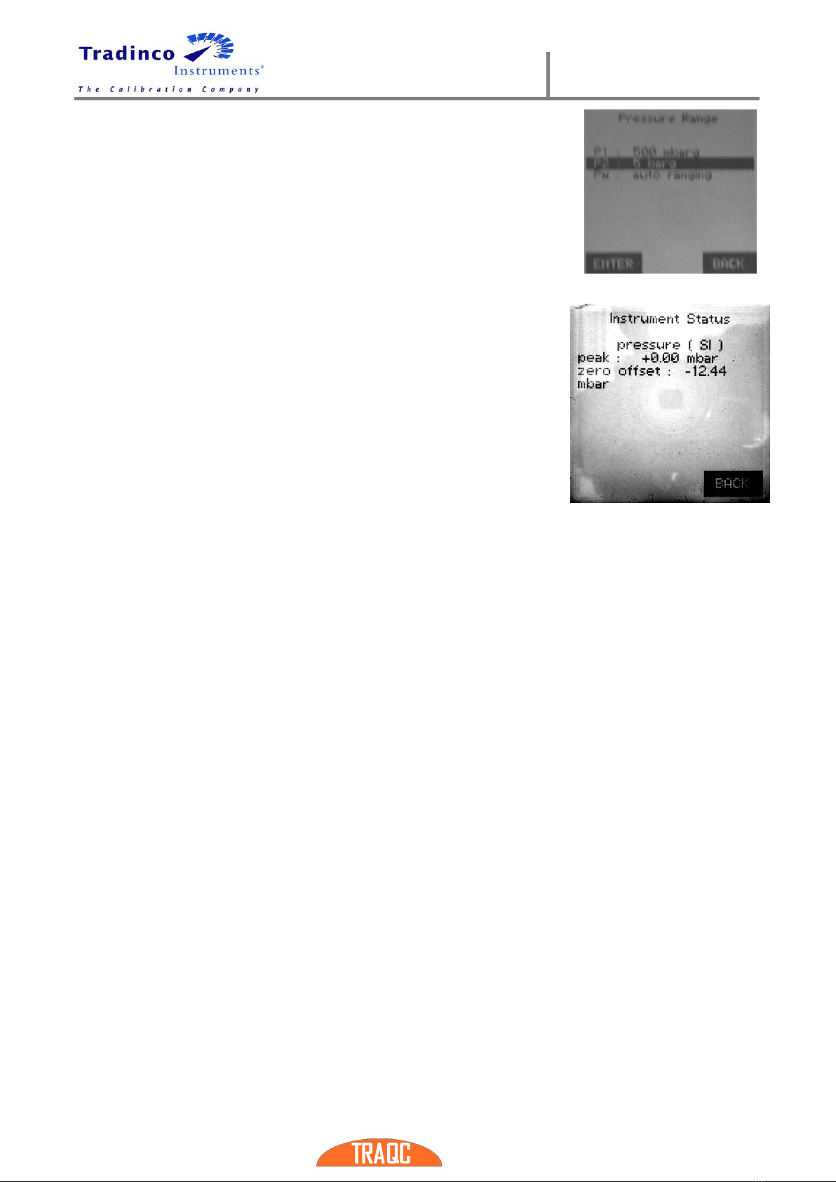
2.11.3 Selecting Pressure sensor Auto ranging
The TRAQC-8 can also be equipped with two pressure ranges and one pressure connection for
measuring test pressure. The TRAQC-8 is configured to automatically switch the measuring
range.
When the test pressure exceeds 101% of the low measuring range the TRAQC-8 will
automatically switch from the low pressure range to the high pressure range. If the test
pressure is lower than 99% of the low pressure range it will automatically switch back to the
low pressure range.
This auto ranging feature will be automatically be enabled when the TRAQC-8 is switched on.
Auto ranging instruments cannot display the measured value from both sensors at the same
time, only the pressure from the selected sensor will be displayed.
User Manual
TRAQC-8
TRAQC-8 04/2017 EN Rev.4 page : 17
To overwrite the automatic switching between the two pressure
sensors, one of the sensors can be selected as described in 2.11.
To enable the auto ranging again:
•Power the TRAQC-9 P off and start it up again.
•By entering the ‘Pressure range’ menu, and selecting the
‘Px auto ranging’ line with the ‘ARROW’ keys and press the
‘ENTER’ key (F1).
2.12Instrument Status
By pressing the ‘LEFT’-or “RIGHT’ ‘ARROW’ key in “measuring mode”
the instruments status is shown.

User Manual
TRAQC-8
TRAQC-8 04/2017 EN Rev.4 page : 18
3.User Configuration
3.1 Pressure Setup
The “Pressure Setup” menu shows the options for pressure inputs.
After pressing the ‘MENU’ key (F1), press the ‘ARROW’ keys until
the “pressure setup” is selected, then press ‘ENTER’ key (F1). The
available pressure options for the instrument are now displayed
(see figure) and it is now possible to select one of options with the
‘ARROW’ keys. The different options of the pressure setup are
described in the following paragraphs.
3.1.1 Pressure range
This menu option is available in instruments with 2 or more
pressure sensors installed.
When you select this option a menu with the available pressure
ranges is shown,
You can select a line with the arrow keys and then switch the
selected pressure range on or off depending upon its current status
when the electrical ranges are not active, otherwise you can select
only one range to be displayed. See also section 2.11.
3.1.2 Pressure unit
The menu to select the pressure unit can in most operating modes be accessed by pressing the
‘UNIT’ function key, There are however operating modes where this is not possible , for these
modes the pressure unit selection is also available in the pressure setup menu, see section 2.10.
3.1.3 Averaging on/off
A progressing averaging can be applied. The reading speed is standard three times per second.
The objective is to display the fluctuating measuring signals in a reliable manner. If averaging is
switched on, this is shown by ‘𝑥’ above the pressure unit reading in the ‘measuring mode’ menu.
To enable or disable the averaging function select the “averaging on/off” option in the “pressure
setup” menu.
The default state is the “averaging off”. To change the current state press ‘ENTER’ key (F1).
3.1.4 Averaging setup
The number of times that averaging must be performed can be set
as follows: Select the “averaging setup” in the pressure setup
menu with the ‘ARROW’ keys and press ‘ENTER’ key (F1) to
confirm. Now use the ‘ARROW’ keys to change the number of cycles
to the desired one, press ‘ENTER’ key (F1) to confirm.
The number of cycles default is 6. The cycles can be set from 3 to
9.
User Manual
TRAQC-8
TRAQC-8 04/2017 EN Rev.4 page : 19
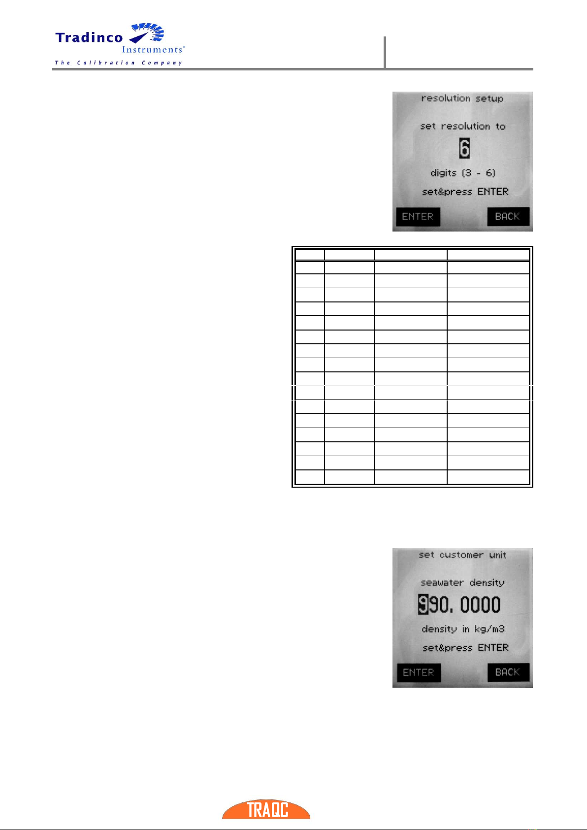
3.1.5 Resolution Setup
To change the number of digits (from 3 to 6) select “resolution
setup” in the “pressure setup” menu and use the ‘ARROW’ keys to
change the number of digits, confirm by pressing the ‘ENTER’ key
(F1)
3.1.6 Conversion Table
The pressure indicator is capable of displaying
pressure according to the SI or the ANSI
standards. Change between SI and ANSI using
the ‘ARROW’ keys and confirm by pressing
‘ENTER’ key (F1).
The ANSI standard has other conversion
factors than the SI standard; see the following
table for a number of units:
3.1.7 Set customer unit
The density of seawater for the region where the pressure
indicator is used can be set here.
When a test pressure is set, the TRAQC-8 can calculate the
pressure into meters under water. The density of the seawater
will differ in different parts of the world and the value has to be
adjusted for correcting for the pressure under water.
The seawater density is set in kg/m3and can be adjusted from
950 up to and 1100 kg/m3.
For adjusting the unit, use the left and right arrow keys to select
the digit which has to be altered and use the up and down arrow
keys for adjusting the selected digit. When the right value has
been set, press the enter key (F1).
Unit
SI
ANSI
01
bar
1
1
02
mbar
1000
1000
03
Pa
100000
100000
04
hPa
1000
1000
05
kPa
100
100
06
Mpa
0,1
0,1
07
psi
14,503768
14,503768
08
kgf/cm²
1,0197162
1,0197162
09
mmH²O
10197,162
10215,491
10
cmH²O
1019,7162
1021,5491
11
mH²O
10,197162
10,215491
12
inH²O
401,46293
402,1598
13
ftH²O
33,455222
33,513316
14
mmHg
750,063755
752,78742
15
inHg
29,52997
29,6373
16
torr
750,063755
750,063755
User Manual
TRAQC-8
TRAQC-8 04/2017 EN Rev.4 page : 20
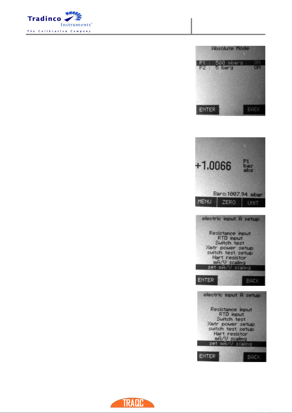
3.1.8 Absolute mode
This option is available when the instrument has two or more
pressure ranges and the last range is an absolute range or
barometric reference sensor.
In instruments with only one gauge range and an absolute range
you can switch the absolute mode on or off, in instruments with
two gauge sensors and a absolute sensor you can select the
range that should be displayed in absolute mode.
Note : In absolute mode the measured value of the absolute
range is added to the measured value of the gauge range. This
means that the uncertainty of the measurement is increased.
When the absolute mode is active the measured barometric
pressure will be displayed on the line just above the descriptions
of the function keys
This pressure is always displayed in mbar.
3.2 Electrical Input A Setup
The electrical connections can be used to measure currents
between 0 - 24 mA, DC voltages between 0 to 11V, resistance of 0
–4000 ohm, temperature with an RTD probe and for connection of
a switch.
To access the menu options for the electrical input first press the
‘MENU’ key, then select the ‘electric setup' line with the ’ARROW’
keys and press the ‘ENTER’ key, will be displayed. The options are
explained in the next paragraphs.
This menu has more than 8 entries, when you step through the
menu with the ‘UP’ and ‘DOWN’ arrow keys the menu scrolls to show
the additional items.
The options are explained in the next paragraphs.
3.2.1 mA Input
To switch the current input on or off select “current input on/off” with the ‘ARROW’ keys and press
Other manuals for TRAQC-8
1
This manual suits for next models
1
Table of contents
Other Tradinco Test Equipment manuals


Popular Test Equipment manuals by other brands


Sanyo
Sanyo MLR-350 instruction manual

Aeroflex
Aeroflex 3500 Operation manual

Hioki
Hioki 9262 user manual

Welch Allyn
Welch Allyn 9600 Plus manual

Chicago Electric
Chicago Electric 91129 Assembly and operating instructions

MAHA Maschinenbau Haldenwang
MAHA Maschinenbau Haldenwang MLT 1000 Original operating instructions