CGOLDENWALL ST-135 User manual

1

2
Preface
Welcome to use CGOLDENWALL steam generator and select one
of ST-135 controller to control it. The steam generator, which has the
reasonable design, stable function and beautiful appearance, uses the
international advanced technology. It equips with special room body to
form the complete set of sauna, which can relax people’s muscle,
eliminate fatigue, and excrete the toxin in the body. Sauna can make
people refreshed and has the function of health care.
To install, operate and maintain the machine safely and correctly,
please read the instructions carefully and keep it in case.
Please pay attention to these when use it;
·Old people, pregnant women, the diabetic, the cardiac and the
people for the other unhealthy reasons can not use the equipment
unless under the guidance of doctor.
·Do not smoke, do sports and drink alcoholic drinks when do
sauna.
. Please leave the shower room as soon as possible when feel
uncomfortable, sick or tired.
·Please take good care of children.
·It is necessary to install a ventilated fan to let in the fresh air.If
you have any questions, please contact us directly by email.
We will guide you online to help you solve the problem sooner
and better.
✉Email:sunflowersmile20130401@hotmail.com

3
CONTENTS
Parameters............................................................................................4
Instructions for Installation..................................................................5
Steam Generator Location...................................................................6
Water Inlet pipe....................................................................................8
Steam Outlet pipe.................................................................................9
Drain pipe and Auto drain valve..........................................................9
Steam nozzle.......................................................................................11
Wiring Connection..............................................................................12
Controller Install Guide......................................................................16
Temperature Probe Install..................................................................17
Start the steam generator....................................................................18
Controller Operation Guide................................................................18
Maintenance operation guidance.........................................................20
Troubleshooting Guidance .................................................................22

4
Parameters
1, models, basic parameters and size of appearance in table 1
Table 1
Power(KW)
Volt/phase number
Size(length*width*height)(
in)
3
220/2
11.8×5.1×9.1
4.5
220/2
12.6×5.1×13.2
5
220/2
12.6×5.1×13.2
6
220/2
15.6×5.9×15.6
7
220/2
17.5×6.5×15.6
8
220/2
17.5×6.5×15.6
9
220/2
17.5×6.5×15.6
10.5
220/2
19.7×7.9×20.5
12
380/3
19.7×7.9×20.5
15
380/3
19.7×7.9×20.5
18
380/3
19.7×7.9×20.5
2, the basic parameters of controllers and the size in table 2
Table 2
Model
time
(minute)
Range of
temperature
Size(length*width*height)
(mm)
ST-135
NO
95 - 131℉
100×100×40

5
Instructions for Installation
The steam generator has been carefully assembled and tested, please
fix in accordance with national laws and regulations. And be fixed by the
people who has local or national plumber certificate. Turn off all the
power in fixing, and make sure that if the type applies for the shower
room. Please look at table 3
Table 3 Technical parameters
Power
(KW)
Room size
(ft3)
voltage
(V)
Phase
number
Copper
wire cable
size (mm²)
Copper wire
cable size
(AWG)
Breaker
required
(A)
3
70~105
220V
2
2.5
12
20
4.5
105~140
220V
2
4
12
32
6
175~210
220V
2
6
8
40
9
315~350
220V
2
10
8
60
10.5
315~420
220V
2
10
8
60
12
360~455
380V
3
6
10
25
15
420~560
380V
3
6
9
30
18
560~735
380V
3
6
8
40

6
Steam Generator Location
1, the steam generator should be fixed in the wall or on the floor firmly,
Select a location as near as practical to the shower room. Typical
locations include: closet, vanity cabinet, climate controlled attic or
basement. In the process of fixing, install the machine on a vertical
wall, release the two screws on the cover, move the cover and then fix
the machine using the holes on the top right and left. Signs should be
put in the obvious place and the generator should be put in the flexible
place for maintaining. Please refer to the figure 1 to fix.
2, do not install the machine outside, or the place where is wet, hot or
the place where is easy for being frozen or eroded. Do not install it
near paint, thinner, or gas. Install it in a dry and ventilation place.
3, the generator can only be installed horizontally.Up in the direction
indicated by the arrow. Otherwise, it is strictly forbidden to boot.
4, locate the steam bath generator within 32 feet of the shower room.The
standard length of the cable for connecting the control to the steam
generator is 32 feet. The steam generator and control must be located
accordingly.
5, do not install steam bath generator inside shower room.
6, do not install steam bath generators or pipes in an unheated attic
or any place where water may freeze.
7, do not install the steam bath generator near flammable or
corrosive materials or chemicals (such as gasoline, paint thinner,
etc.). Must avoid installation in areas with high chlorine
concentration (such as swimming pool room).
8, Provide a minimum of 12 inches at both ends and top of the steam
generator or as required for servicing.

7
attic floor(insulated)
suitable for installation
Controller (suitable
be installed outdoors)
closet
(suitable for installation)
basement
(suitable for installation)
steam generator
Controller (suitable
be installed outdoors)
steam jet
under the wash basin
(suitable for installation)

8
Pipe installation
Water source pipe and steam pipe should be installed in accordance
with national laws and regulations. The installation should be done before
sealing walls.
1, Water inlet pipe--the water inlet pipe is connected with the DN15 pipe
(1/2 NPT). And a DN15 metal hose is connected to the water inlet and
water supply valve of the machine.
Connect to cold water .
Provide a shut off valve in the water supply line upstream of the
steam bath generator.
Do not overheat inlet solenoid valve while welding connections.
Overheating will damage parts.
Flush inlet water line thoroughly before connection to unit.
Strainer recommended to install upstream of feed water connection
The best performance water pressure should be 15 to 20 PSIG.
Reduce pressure as required if necessary.
As required by local codes, install an approved backflow preventer.
Do not use PEX , PVC tubing or Aluminum-plastic tube

9
2, Steam outlet pipe---steam pipe should use copper pipe longer than
DN15 (ferrous metal and galvanized pipe was not allowed to use for it
can make the shower room rust and discolor). The length of steam
pipe was no more than 3 meters. It should be used for keeping warm
if it is longer than 3 meters. (Please refer to figure 3)
1. Do not install any valve in steam line. Flow of steam must be
unobstructed.
2. Use 1/2” brass pipe or copper tubing from unit to steam head as
permitted by codes.
3. Insulate steam line using pipe insulation rated 250˚ F or higher.
4. Pitch steam line 1/4” per foot towards steam head or steam
generator to avoid valleys and trapping of condensation.
NOTE: Running the steam line down and then up will create a steam
trap blocking the flow of steam.
NOTE: A 1.5 ”hole in the shower room is required to mount the
steam head
3, Drain pipe and automatic drain valve( 1 ⁄2’’ NPT)
It is necessary to install a DN15 pipe
A drain valve is provided to facilitate servicing. Provide a drain line
connection with the steam bath generator.Unit drains by gravity. The auto

10
drain is automatically turned on after the controller is turned off for about
15 minutes, but it must be ensured that the main power supply is not
turned off.
1. Plumbing to be performed by a qualified plumber and shall be in
accordance with applicable national and local codes. Steam generator
drains by gravity. A drain line should be lower than the Auto Drain
System assembly . The Auto Drain System valve outlet is 1/2”NPT.
Check plumbing code for receptor, trap and vent requirements.
2. Use copper or brass nipple 1/2”NPT x 3 , 1 ⁄2”or longer (not
supplied) to connect Auto Drain valve. An arrow on the bottom of the
Auto Drain indicates the direction of flow

11
4, Steam nozzle---in the shower room, put the decorative pipe over the
steam pipe and smear the sealant, and then spin on the nozzle. Do not
put forth strength excessively in case of damaging the decorative pipe
and steam nozzle. Make sure nozzle point to the floor.
Note: The steam nozzle should be 30cm high from the ground or 20cm
high from the edge of the bathtub. For the comfort of the shower, the
nozzle should be installed as far as possible from the seating area.
After the in stall, the electrician can continue the wiring.
Warnings:
·If the generator was stalled far from the place where is easy
operated, water supply valve should be fixed in the place of easy
operation in emergency.
·Do not use saddle valve or needle valve in the inhalant siphon.

12
Keep the pipe dredged and clean before connect the last pipe.
·Do not install blocking valve in the steam pipe. The blocks or ‘U’
shaped channel may result condensate and prevent the
circulating. The steam pipe should be a little declining so the
condensate can flow to each side.
·To prevent be frozen, the steam generator can not be installed
outdoor. The steam generator must be fixed in the place of easy
maintaining and the machine should be installed horizontally
and keep the arrow up or the machine will not turn on.
·The pipeline must be copper pipe. Do not use plastic, acrylic,
plastic pipe or other similar material as the pipe. For the highest
temperature of them if no more than 150℃.
·Make sure other pipes are sealed when steam is in, or the steam
will damage the machine and other parts of it.
·If the water in the radiator flew into shower room, it can result in
scald accident or hurt the building materials for the shower
room.
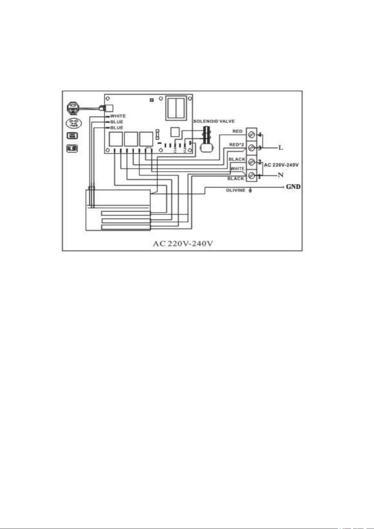
Wiring Connection
The machine has been carefully assembled and tested; please fix the
circuit in accordance with national laws and regulations. The wiring
connection must be carried out in accordance with national regulations
and by professionals who have obtained local or national professional
electrician qualification certificates. The power must be turned off before
making any wiring connections.Please refer to the following wiring
diagram for complete wiring information

13
TO AVOID EQUIPMENT DAMAGE, DO NOT CONNECT POWER
SUPPLY DIRECTLY TO ELEMENTS!!!
Wiring diagram
If you are in 110V countries, like America, you need to connect to
TWO DIFFERENT 110V live wires(L1 and L2). NO neutral wire is
required. L1, L2, Ground to be field wired
14
If you are in other 220V countries, you need to connect to one 220V
live wire and one neutral wire (L and N). For both, a ground wire is
needed. L1, N1, Ground to be field wired
When installing the steam generator, please note that it has been
carefully assembled and tested by our technician. The pipe installation
must be in accordance with the specifications. Or consult a professional
with local or national plumber qualification certificate for installation.
Please turn off power when installing the steam generator and confirm
whether the purchased model is suitable for your shower room. Please
refer to Table 3.
Steam generator power supply installation:
1, make sure of the right supply voltage (220V or 380V, see the sign),
please refer to the materials in the sign or instruction of the machine.
2, the request for installing the circuit breaker in the process of circuit
installation must be carefully in accordance with table 3. The machine
must install earth wire. Please install CFI (international electric

15
principal 210--8).
3, select the proper electric circuit trace according to the local request.
Please install the socket near the steam generator if it is necessary.
The current load of plug and socket should be more than 250V. After
the sealing wall, the machine and the controller’s wiring can be done.
4, release the screw and open the top. Open the power leading-in blind
via in the right side of the machine.Connect in strict accordance with
the wiring method on the power wiring diagram label (the wiring
diagram label is on the chassis cover). The machine can be turned on
after the installation controller.
Check terms
Please check the machine under these terms before using it
1, make sure the machine connect earth, and the earth wire’s width
should wider than 4mm2。
2,check if the model is proper, if not, the shower room will not reach
the highest temperature.
3, choose the proper steam generator (220V or 380V). The heater and
the board will be damaged if 380V were connected to the 220V
steam generator. The power will reduce 25% if 220V were
connected to 380V steam generator. Zone line of 380V’s steam
generator must be connected rightly, that is zone line can not
connect phase, or the heater and board will also be damaged.
4, the steam generator must be stalled vertically.
5, choose right cable and circuit breaker.
Warnings;
·Turn off all the power before stall and maintain the machine.
·Do not add additional wires and power to the machine. Make sure

16
earth wire has not linked to the electric wire. Please use parts of
Source Company for safe usage of machine in the process of
installation, operation and maintain.
Controller Operation and Install
ST-135 temperature controller’s installation direction
1, controller’s installation location— installed inside and outside the
shower room , and sealed by silicone adhesive.For controller power
supply connection,the connection line is one head connect to the
controller, another head connect to the control panel.The standard length
of the cable for connecting the control to the steam generator is 32 feet.
The steam generator and control must be located accordingly.
2, ST-135 controller’s Installation—controller can be installed indoor or
outdoor of the steam .For convenient use, please install it far from the
earth 1500mm. the wall must drill a hole for fixing the controller from
the back. Two control lines in the back of the controller should be
inserted the corresponding jack separately. Peel the double-sided
adhesive tape film on the controller’s back and use silicone seal the

17
wall. (note; 1, control line muse be installed inside the ray tube for
maintaining. 2, the double-sided adhesive on the controller’s back
can not work for fixed function and glass glue should be used to
fix.)
Temperature probe installation
The temperature probe induces the temperature in the shower room. Its
installation height is 1.5m and it should be fixed inside the shower room
by screws.
One head of the temperature probe line connect to the control
panel.Another head of the temperature probe with sensor must be
fixed inside the steam shower by screws,and on a vertical surface, 4-5
feet above the floor and should be exposed to the air.
Drill a 1/4”hole in the wall. The hole should not be too large or too
small. Clean the area thoroughly.
Route the end of the temperature probe cable with the temperature
probe through the wall into the shower room as picture.

18
Do not locate the probe above or near the steam head or direct steam
emissions. The probe is 10ft cable. Ensure that the probe and
controller are located accordingly.
IMPORTANT NOTE: Do not strain, staple, pinch, otherwise damage the
probe cable.
Start the steam generator
After confirming that the pipes and circuits are installed correctly, you
could open the water valve and turn on the power switch. Press the
ON/OFF and the machine will start to work. After heating for minutes,
the machine starts to emit steam, and stops steaming until the room
reaches the set temperature.
Press the ON/OFF button again to turn off the machine. The controller
will display the current temperature in the shower room when it is
working. The temperature setting range of the controller is between
95-131℉.
Warnings;
·The machine must be connected with the ground.
·Do not install the machine and controller in wet place. It should be
installed in dry and ventilated place. Our company will not take
the responsibility if it is damaged by wet.
·The double-sided adhesive on ST-135 the controller’s back can not
work for fixed function and glass glue should be used to fix.
Controller’s operation direction
1, temperature display window; the temperature is shown in shower room
when steam generator in work
2, heating indicator light; generator is heating for steam when lights on
3, heat lamp; shower room reaches setting temperature when light on, the

19
machine begins to work automatically to keep temperature stable in the
room.
4, start/stop key; the machine begins to work when touch the key softly,
and then generate steam in few minutes. The machine will stop when
touch the key again.
5, temperature setting key; when the machine is on, press the temperature
setting key and set the temperature. Press START/STOP key to
adjustment temperature and then the setting temperature is shown in
the screen. Press the setting key again or quit the setting status in 15s
after the proper temperature. The setting temperature range is from 95
℉to 131℉.
SET
TEMP
START
ON/OFF
Temperature display
Heat indicator light
On/off key
Digital by/down key
Temperature
setting key
ST-135
Controller
Heating indicator
light

20
Steam generator’s maintenance
Steam generator’s maintenance
1, check steam generator, steam nozzle, parts and pipelines regularly to
prevent the damage coursed by steam and leak.
2, the machine equips with auto drain valve for discharging precipitate in
the generator. The work is done every month or even more frequently
depending on water quality or generator’s using.
Cleaning process: The auto drain is automatically turned on after the
controller is turned off for about 15 minutes, but it must be ensured that
the main power supply is not turned off. (the machine is not heat when
draining water).
3, please check any over-heat omen when the machine is on. Check the
firmness of all the parts.
Maintenance operation direction
1, change heater; turn off the power, drain water tank’s water, open the
front cover and pipeline’s cover, mark the wire’s interface and remove
the wire and get out the heater. Then, take a new heater; cover the
heater’s wire pipe with a rubber ring, and after cleaning the dirt, sleeve
the heater and tighten it (tighten the sleeve ring but not turn out). After
connecting the heater, check if it is leaking and then cover the covers
well.
2, change circuit board; turn off the power, open the front cover, and pay
attention to the water level that blue and write water level probe point
to. Take down the probe and the three lines on the board. Mark the
connection interface and take down the board. Install adopts the
opposite stages with above.
3, change solenoid valve; stop power and water source, and open the front
cover. Take off two blue wires from solenoid valve. Then take off the
Table of contents


