cGuard 285 User manual
cGuard 285
User guide

1
cGuard 285 –User guide
1
Contents
1. Copyrights and guarantees ...................................................................................................2
2. Introduction .........................................................................................................................3
3. Specifications ......................................................................................................................4
4. Set contains..........................................................................................................................6
5. Components of cGuard 285..................................................................................................6
6. Interface connector description ............................................................................................7
7. First-time setting..................................................................................................................9
7.1 Channel setting ..............................................................................................................9
7.2 Remote configuration...................................................................................................12
8. Connecting the automobile cGuard tracker.........................................................................13
8.1. Inserting a SIM-card ...................................................................................................13
8.2. GPS/GLONASS-antenna installing .............................................................................14
8.3. GSM-antenna installing...............................................................................................14
8.4. Power connection........................................................................................................14
8.5. Connecting the analog inputs of tracker.......................................................................16
8.6. Connecting the frequency/pulse inputs of tracker ........................................................18
8.7. Connecting the power output of the tracker .................................................................19
8.8. Connecting devices to RS-485 interface ......................................................................19
8.9. Connecting CANLog to RS-232 interface ...................................................................20
9. Device status indication .....................................................................................................23
SAT indicator ....................................................................................................................23
DAT indicator....................................................................................................................23
10. Contacts.........................................................................................................................24

2
cGuard 285 –User guide
2
1. Copyrights and guarantees
This guide contains descriptions of the device and its functionality, and methods of its
connection and installing
This guide is designed for specialists acquainted with repair and installation work on automobile
transport and having professional knowledge about electronic and electric equipment of various
vehicles. All the data about functions and specifications and other information in this guide is
mentioned to be actual for the publication date. cGuard LLC company keeps its right to make
changes in this information and specifications without additional notifying.
cGuard LLC company isn’t responsible to any harm or problems, caused by using functions or
consumables other from original cGuard products or approved by cGuard.
cGuard LLC company isn’t responsible for any harm, problems, losses or expenses caused by
inappropriate using of a product, accidents, unwarranted modification, repair or changes in
product, or impossibility to strictly follow the working and service instructions worked by
cGuard. Important!
Officially released by cGuard LLC and recommended to install on trackers are
firmware versions named like this:
fw-[fnxx-]a.b.c-hash
fw-[fnxx-]a.b.c-[oem-]hash
here:
fw –short for “firmware”;
fnxx –here n –digit corresponding to processor type in tracker;
a.b.c –firmware version;
oem –sign of a company the special firmware designed for;
hash –hash-code.
Data in square brackets is optional.
Ex.: fw-f2xx-3.0.9- 4fc22f89439a
Firmwares like:
fw-[fnxx-]a.b.c[rck]-hash - release candidate
fw-[fnxx-]a.b.c-dev[-description]-hash - test version
fw-[fnxx-]a.b.c-hash+ - developer version, provided to
users only in special cases
can be installed to tracker under user’s responsibility, and cGuard LLC isn’t
responsible for any negative consequences caused by using these firmwares.
Version of a firmware installed on tracker is shown in configurator (“Tracker” tab) (see «first-
time setting»)

3
cGuard 285 –User guide
3
2. Introduction
This guide represents the user instructions for the user terminal of transport monitoring cGuard
285 ((“Tracker” as further in text), designed for monitoring vehicles by executing following
functions:
Real-time locating current vehicle’s position;
Sending data to server for tracking the vehicle in monitoring system;
Vehicle’s mileage count;
Detecting of passing the checkpoints of the route by vehicle;
Determination of current speed and computing the average speed in specified time
interval;
Counting the time of a vehicle’s standing period;
Measuring the voltage of the vehicle mains;
Control over vehicle’s parameters by measuring analog and discrete signals from
state vehicle’s sensors (ex. fuel level or engine’s temperature sensors, door-
operated switches etc.);
Control over vehicle’s or load’s parameters by installing addictive sensors of
other manufacturers;
Ability to detect driver’s actions performed in order to prevent the control process
by remembering the moments of voltage disappearing and recovery and
positioning signals;
Detecting the driving’s quality.

4
cGuard 285 –User guide
4
3. Specifications
Global positioning system:
Satellite system.............................................................................................. GLONASS/GPS
Cold start, s.......................................................................................................................... 35
Hot start, s............................................................................................................................ 10
Channels.............................................................................................................................. 99
Navigational receiver sensitivity, dBm..............................................................................-165
Position accuracy, m.............................................................................................................. 3
GSM:
GPRS multi-slot class ....................................................................................................... 10/8
GPRS mobile station class .....................................................................................................B
Frequency range, MHz...............................................................................850/900/1800/1900
SIM-cards quantity, pcs. ........................................................................................................ 2
Energy consumption:
Power voltage, V............................................................................................................ 8,5-40
Maximum power voltage, V................................................................................................. 44
Consumable amperage (average), not more, mA ...............................................................1501
Maximum (peak) consumable amperage, mА.................................................................... 250
Maximum consumable amperage while charging internal battery, mA............................... 350
Internal battery.................................................................................................................Li-po
Nominal voltage of internal battery, V .............................................................................3.7 В
1All device parameters measurements, except special case, were made by nominal power voltage 12,0 ± 0,5 V.

5
cGuard 285 –User guide
5
Interfaces:
Analog inputs (0..30 V), pcs....................................................................................................3-42
Frequency/pulse (0..30 V), pcs............................................................................................... 4
Power output with open drain (30 V, 1 A), pcs........................................................................3-42
RS-485 (TIA/EIA-485-A), pcs............................................................................................... 1
(RS-232, pcs. ......................................................................................................................... 1-23
1-Wire, pcs. ........................................................................................................................... 1
Audio output “Autoinformer”', pcs. ....................................................................................... 1
Microphone input, pcs. .......................................................................................................... 1
CAN, pcs............................................................................................................................... 1
microSD, pcs. ....................................................................................................................... 1
USB 2.0, pcs. ........................................................................................................................ 1
General:
PC-connection interface..............................................................................................USB 2.0
Internal nonvolatile memory, MB/route points.....................................................16 / 200 тыс.
Internal accelerometer.......................................................................................................Есть
Temperature:
Operating temperature range, ˚С................................................................................- 35..+50
Storage temperature range, ˚С....................................................................................- 40..+50
Physical parameters:
Dimensions, mm..................................................................................................100x22x74.5
Case material ......................................................................................................... Aluminium
2Depends on hardware version (8.0 or 8.1), analog inputs and power outputs quantity may vary (3 or 4). Pinout is shown on one
of the device’s case surfaces.
3Depends on hardware version (8.0 or 8.1), RS-232 interfaces quantity may vary. 8.0 version –2, 8.1 version –1.
6
cGuard 285 –User guide
6
4. Set contains
1. cGuard 285 tracker..................................................................................................1 pcs.
2. GPS antenna ...........................................................................................................1 pcs.
3. GSM antenna ..........................................................................................................1 pcs.
4. Micro-Fit connector 12x2........................................................................................1 pcs.
5. Wires set.................................................................................................................1 pcs.
6. Device passport.......................................................................................................1 pcs.
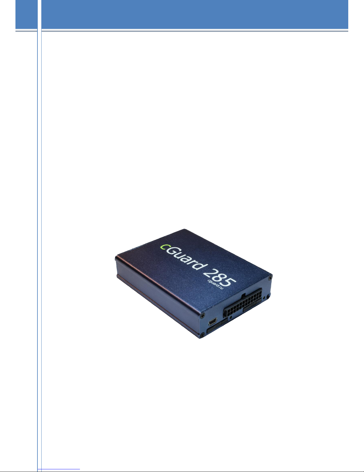
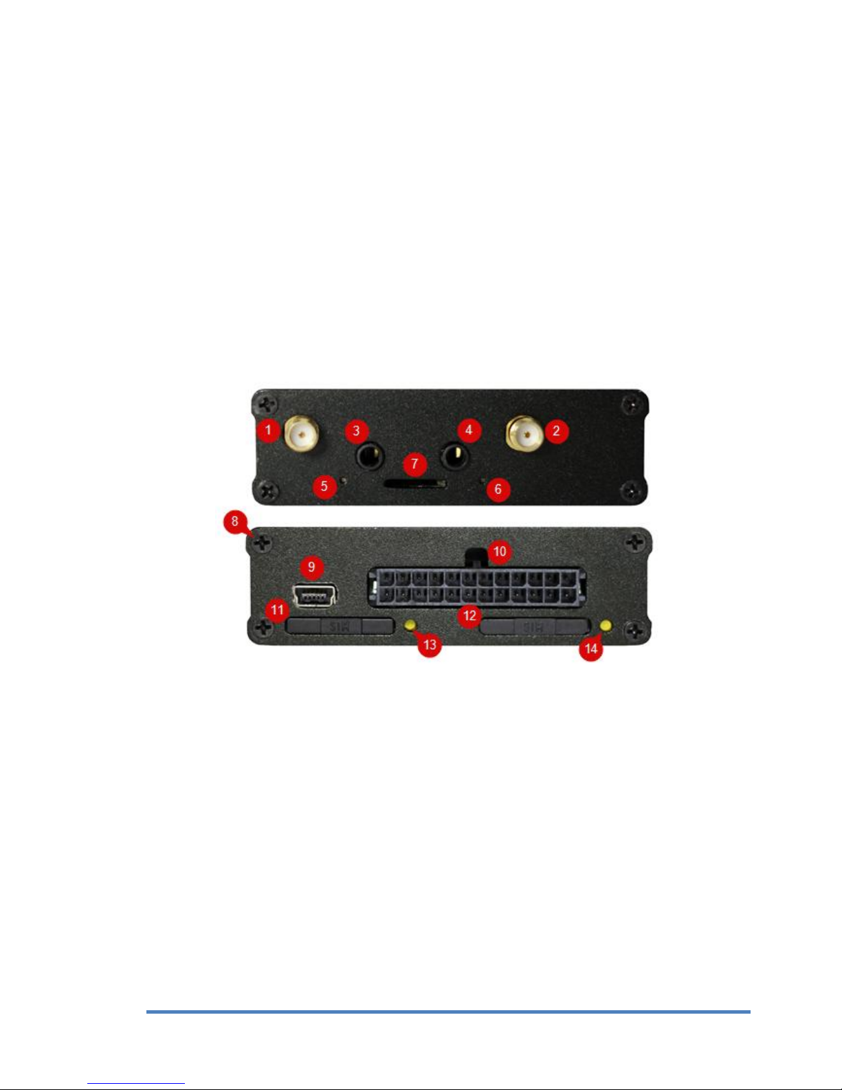
5. Components of cGuard 285
Pic.1.Components of a tracker
1. GSM antenna connector
2. GPS/GLONASS antenna connector
3. MIC input
4. SPKR input
5. Positioning status LED - STAT
6. GSM status LED –DAT
7. Memory card slot
8. Screws (8 pcs)
9. miniUSB
10. MicroFit connector 12x2
11. SIM-card slot (SIM2)
12. SIM-card slot (SIM1)
13. SIM2 removing button
14. SIM1 removing button

7
cGuard 285 –User guide
7
6. Interface connector description
Pic.2.Interface connector
Table 1.Pinout for external sensors installation for hardware version 8.0
Contact number
Input purpose
1
Analog/Discrete input (0-30 V) 1
2
Analog/Discrete input (0-30 V) 2
3
Analog/Discrete input (0-30 V) 3
4
Frequency/pulse input 1
5
Frequency/pulse input 3
6
Frequency/pulse input 2
7
Frequency/pulse input 4
8
Power output with open drain 1
9
Ground
10
Power output with open drain 3
11
1-Wire (DATA input)
12
Power output with open drain 2
13
RS-232 (TX) 2
14
Autoinformer output “+”
15
RS-232 (RX) 2
16
Autoinformer output “-”
17
RS-232 (RX) 1
18
RS-232 (TX) 1
19
RS-485 (Вinput)
20
CAN (LO input)
21
RS-485 (Аinput)
22
CAN (HI input)
23
Main power minus
24
Main power plus

8
cGuard 285 –User guide
8
Table 2. Pinout for external sensors installation for hardware version 8.1
Contact number
Input purpose
1
Analog/Discrete input (0-30 V) 1
2
Analog/Discrete input (0-30 V) 2
3
Analog/Discrete input (0-30 V) 4
4
Analog/Discrete input (0-30 V) 3
5
Frequency/pulse input 1
6
Frequency/pulse input 2
7
Frequency/pulse input 4
8
Frequency/pulse input 3
9
Power output with open drain 1
10
Power output with open drain 2
11
Power output with open drain 4
12
Power output with open drain 3
13
Ground
14
Autoinformer output “+”
15
1-Wire (DATA input)
16
Autoinformer output “-”
17
RS-232 (RX)
18
RS-232 (TX)
19
RS-485 (Вinput)
20
CAN (LO input)
21
RS-485 (Аinput)
22
CAN (HI input)
23
Main power minus
24
Main power plus

9
cGuard 285 –User guide
9
7. First-time setting
The cGuard trackers can be configured by using official application –cGuard Configurator. This
program allows to set tracker’s parameters for GPS/GLONASS monitoring and also to tune the
data exchange and analysis to work with data from tracker and external devices.
Actual version of this application can be downloaded from manufacturer’s website.
Pic.3. cGuard Configurator
“Tracker” tab contains general information about tracker, its location, IMEI, ID and current
firmware version. Also, there’s the ability to change the unique ID (for identifying the device in
monitoring system), upload the firmware, and to upload the configuration (saved to file before).
More about working with configurator can be seen in the remote configuration guide on the
website.
7.1 Channel setting
For tracker status monitoring and working with external devices it is necessary to set up the data
channels. It can be done in “Channels” tab in configurator.

10
cGuard 285 –User guide
10
Pic.4.Channel setting in cGuard Configurator
Configurator shows the channel data values in real time, allows turning on/off data sending from
each channel and setting the sending conditions. The list of available channels of cGuard 285 is
shown in the table 2. The correspondence between channels and inputs can be seen in table 3.
It is important to turn on the data sending of a channel with data from external sensor
after connecting the sensor to tracker (channel choosing depends on input connected
with sensor, and on sensor purpose).
To allow the data sending for the channel, go to “Channels” tab in configurator, then select the
needed channel in the channel list, get sure that the name of this channel is shown at the right
side (“Per-channel settings”) and set at least one of the sending conditions.
Table 3. cGuard 285 channel list
Channel
Purpose
Values
Notes
CSQ1
GSM signal level
0..100%
CSQ2
Active SIM-card number
1 or 2
NSQ1
Captured satellites quantity
0..24
NSQ2
Satellites data validity
0 or 1
1 –valid, 0 - invalid
AIN1..AIN4
Analog channels
0..30 V
DIN1..DIN4
Discrete channels
0 or 1
See. section 8.5
BAT1
Battery charge level
0..100%
PWR1
Mains voltage
0..40 V
REL1..REL4
Relay control
0 or 1
1 –on, 0 - off
FRQ1..FRQ4
Frequency channels
0..2000 Hz
CNT1..CNT4
Pulse counter
0..4294967295

11
cGuard 285 –User guide
11
CAN1..CAN8
CAN-bus data
CLG1..CLG8
CANLog data
See. section 8.9
WIR1..WIR3
1Wire sensor temperature
IBT
iButton ID
LLS1..LLS12
Digital sensors data (RS-485)
See. section 8.8
Table.4 Correspondence between logical channels and physical inputs of tracker
4ADC marking was indicated on trackers cGuard 285 manufactured earlier than February 2015.
Input
Channels
AIN1 (ADC1)4
AIN1 –value of voltage on analog input
DIN1 –result of program comparator, comparing the analog input signal and
assigned threshold
AIN2 (ADC2)4
AIN2 –value of voltage on analog input
DIN2 –result of program comparator, comparing the analog input signal and
assigned threshold
AIN3 (ADC3)4
AIN3 –value of voltage on analog input
DIN3 –result of program comparator, comparing the analog input signal and
assigned threshold
AIN4 (ADC4)4
AIN4 –value of voltage on analog input
DIN4 –result of program comparator, comparing the analog input signal and
assigned threshold
DIN1
FRQ1 –frequency measuring
CNT1 –pulse counter
DIN2
FRQ2 –frequency measuring
CNT2 –pulse counter
DIN3
FRQ3 –frequency measuring
CNT3 –pulse counter
DIN4
FRQ4 –frequency measuring
CNT4 –pulse counter
RS-485
LLS1-LLS12
CAN
CAN1..CAN8
RS-232
CLG1..CLG8
1Wire
WIR1..WIR3
IBT1 - for iButton
DOUT1
REL1
DOUT2
REL2
DOUT3
REL3
DOUT4
REL4

7.2 Remote configuration
There are two data channels for remote configuration:
SMS
GPRS
The remote configuration guide and the list of available commands can be downloaded from our
website.
GPRS configuration allows customizing device parameters and uploading device firmware.
SMS-commands can change device parameters and make requests for device status and location.

13
cGuard 285 –User guide
13
8. Connecting the automobile cGuard tracker
8.1. Inserting a SIM-card
Tracker sends data to server by using GSM net, so it needs a SIM-card. To insert the SIM-card
follow these instructions:
1. Push the SIM-card removing button by some thin object (clip or toothpick) and remove
the Sim-card holder.
2. Put SIM-card into a holder (upside the contacts).
3. Carefully, without too much force, put the holder with the SIM-card into the slot until it
fixes.
Pic.5. SIM 2 slot
Important! If tracker is mentioned to work with only one SIM-card, insert it into
the SIM 2 slot of the tracker (pic. 5).
Important! Before inserting the SIM-card, get sure that it is able to work, try it
in the mobile phone before installing it into a tracker. Get sure that PIN-code
checking is turned off. If possible, get sure that GPRS/SMS/USSD services are
working, and the balance of an account is positive and it’s enough for normal
functioning of GSM services.
To make the process of setting up the SIM-card easier you can use M2M SIM-card.

14
cGuard 285 –User guide
14
8.2. GPS/GLONASS-antenna installing
While paving the antenna’s wire avoid sharp objects and razor-edges of metal details.
Any changes made to antenna’s wire (changing, increasing, etc) are forbidden.
Antenna and antenna’s wire and connectors should not be short to ground, it will cause the
failure of a tracker and lead to an expensive repairs.
GPS/GLONASS-antenna should be attached to a metal base and be placed in a most open
space to get the signal freely; its active surface should be directed to the sky.
Connect the GPS/GLONASS-anttena from the set (square-shaped one, with magnet base) to
its connector on the tracker. Screw-nut should be connected tightly, but without too much
forcing.
8.3. GSM-antenna installing
While paving the antenna’s wire avoid sharp objects and razor-edges of metal details.
GSM-antenna should not be attached to metal or any conductive surface.
Any changes made to antenna’s wire (changing, increasing, etc) are forbidden.
Antenna and antenna’s wire and connectors should not be short to ground, it will cause the
failure of a tracker and lead to an expensive repairs.
Connect the GPS/GLONASS-anttena from the set (long-shaped one, with adhesive base) to
its connector on the tracker. Screw-nut should be connected tightly, but without too much
forcing.
GSM-antenna should be attached to the glass, so the surface should be cleaned and
degreased; to place it to the prepared surface remove the protective film from the adhesive
surface of antenna and stick it to the glass.
8.4. Power connection
Before connection the power to the tracker get sure that the mains voltage fits the acceptable
range (see the section “Specifications”).
Important!
Keep the power polarity!
It is necessary to set a 2A fuse to the power circuit!
Plug in the connector with the crimped wires to the X1 connector in the tracker, to connect the
GND contact to the wire of the main power, and PWR contact to the plus wire of the main
power. The wires’ cut must be 0.5 mm or more. All connections must provide dependable
contact and be safely isolated.
The preferable version is connection the tracker to the mains after the ground switcher (see
pic. 6).

15
cGuard 285 –User guide
15
Pic.6. Connecting the main power to the X1 connector after the ground switch scheme
There is also the ability to connect the device straight to the accumulator, bypassing the ground
switch. In this case it’s recommended to put the 2A fuse on minimal distance from the point
where the tracker is connected to main power.
Pic.7.Connecting the main power to the X1 connector before the ground switch scheme
16
cGuard 285 –User guide
16
In case when the tracker is connected straight to the battery, bypassing the ground switch, it’s not
recommended for the vehicle to have long-time downtimes (more than 3 days).
When doing the electric welding on the automobile, or when the engine is starting by the
external current source the tracker must be disconnected from automobile board mains!
Otherwise the device can break down.
To prevent the intervention to device’s work and intentional damage it is recommended to seal
up the connectors, terminal blocks and the case of the tracker after its installation.
After the installation and connection the device is ready to work. If it was connected
appropriately, it starts the work automatically. The LED indication of the right working device
can be seen in the following section of this guide.
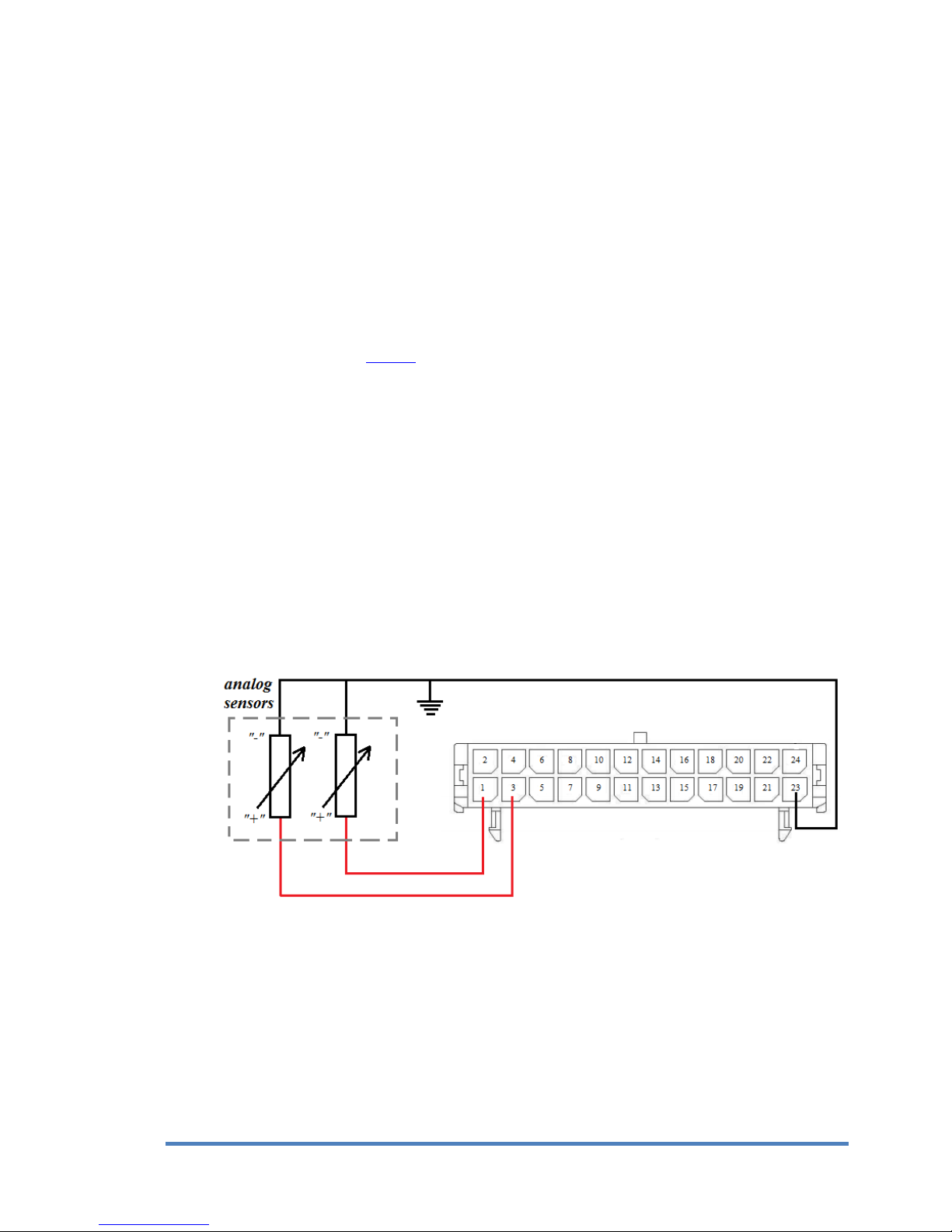
8.5. Connecting the analog inputs of tracker
Tracker has three or four (depending on hardware version) analog inputs (AIN1..AIN4) available
in the interface connector X1. These inputs can be used for measuring the direct current voltage
in range 0..30 V.
Analog inputs can be used for measuring the vehicle parameters with value proportional to the
voltage level (ex. fuel level value from internal or external sensor).
To increase the accuracy of measurements it’s recommended to draw the minus wire directly
from the sensor, but it’s acceptable to use the common ground.
Typical scheme of connecting the sensor to analog input can be seen on pic. 8.
Pic.8. Installing analog sensors to AIN input
There are two ways of analyzing data from analog input, by the setting AIN or DIN channel with
corresponding number:
AIN channel shows the voltage on the corresponding input;
DIN channel indicates that the voltage on this input is higher, than the threshold, assigned
in TLD parameter for this channel. If the voltage is higher, than this threshold, the
channel value is 1, if it’s lower –0.
17
cGuard 285 –User guide
17
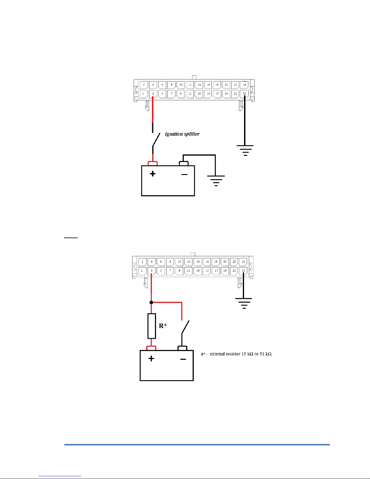
In case analog input is used for detecting the automobile ignition, use the following schemes.
If there’s a plus-circuit splitter in the automobile, use the scheme from pic. 9 to detect the
ignition.
Pic.9.Ignition detecting in plus circuit
If there’s a minus-circuit splitter in automobile, use the scheme from pic. 10.
Note: external resistor 15 kΩ to 51 kΩ, capacity from 0.1 W.
Pic.10. Ignition detecting in minus circuit
To detect the automobile ignition it is recommended to use the DIN channel with parameter TLD
set to value 8. It is acceptable to use the AIN channel instead, but in this case the threshold must
be set in virtual ignition sensor in monitoring system.

18
cGuard 285 –User guide
18
8.6. Connecting the frequency/pulse inputs of tracker
Tracker has 4 frequency/pulse inputs (DIN1.. DIN4), One of the working modes (frequency or
pulse) can be chosen for each of them.
Each of the 4 inputs can be configured individually.
To connect the sensor to this input, plug in the connector with the crimped wires the way to
connect the GND contact to the ground, and the DIN1 or DIN2 to positive output of external
sensor (pic.11).
Pic.11. Installing the sensor with frequency output to the tracker
Get sure that the incoming voltage for these inputs fit the appropriate range:
2..30 V.
External sensors must be serviceable and provide dependable work. Otherwise,
manufacturer isn’t responsible for right sensor status registration (losing the
contact etc.).
To work with sensor data set up the corresponding channel in configurator (as seen in Channel
setting in configurator):
To count the pulses from sensor set the CNT channel;
To measure the frequence set the FRQ channel

19
cGuard 285 –User guide
19
8.7. Connecting the power output of the tracker
Tracker has three or four power outputs (depending on hardware version). It can be used for
controlling the external executive devices.
Important!
Maximum acceptable load voltage must not be higher than 30 V.
Maximal acceptable amperage - 1 А.
Typical load connection scheme (pic. 12) example - OUT1, model 8.0.
Pic.12.Power output load connection
For external device control use the channel REL1. When its value is set to 1 (in configurator or
by remote command (SMS or TCP, see remote configuration guide on the website)), the ground
circuit of the controlled device (“load” on the pic. 12) connects with ground circuit of a vehicle,
providing the device work. When the value is 0, contact disconnects.
8.8. Connecting devices to RS-485 interface
Tracker has an ability to read data from digital sensors by RS-485 interface (those that work by
LLS protocol). This interface allows connecting several sensors simultaneously. Typical scheme
of connecting devices to this interface is on pic. 13.
Pic.13. Connecting device to RS-485 interface
Table of contents
Other cGuard GPS manuals

Popular GPS manuals by other brands


Navigon
Navigon 10000300 - 2100 Max - Automotive GPS... user guide

Prestigio
Prestigio RoadScout 4150 Important safety instructions

Accurate Technology
Accurate Technology GT06AB user manual

Prestigio
Prestigio GeoVision 5056 Navitel quick start guide

Medion
Medion MEDION-Navigator 4.4 user manual

Callaway
Callaway uPro MX manual