CH Hanson Norse 9683125 User manual

Operating Manual & Parts List
9683125
14˝
BAND SAW
Read care ully and ollow all sa ety
rules and operating instructions be ore
irst use o this product.
9644165.01-0419
2
NORSE Operating Manual & Parts List 9683125
GETTING STARTED
STRUCTURAL REQUIRE ENTS
Make sure all supporting structures and load attaching devices are
strong enough to hold your intended loads. If in doubt, consult a
qualified structural engineer.
ELECTRICAL REQUIRE ENTS
The power supply to the Band Saw needs to be 120 volt/ 3.4 amp, single
phase, 60 Hz. The standard allowable voltage variation is plus or minus
10%.
TOOLS NEEDED:
Standard mechanic’s hand tool set.
UNPACKING
WARNING: Be careful not to touch overhead power lines, piping,
lighting, etc. if lifting equipment is used. Band Saw weighs
approximately 204 lbs, proper tools, equipment and qualified
personnel should be employed in all phases of unpacking and
installation.
Carton should be handled with care to avoid damage from drop-
ping, bumping, etc. Store and unpack carton with correct side up.
After unpacking Band Saw, inspect carefully for any damage that
may have occurred during transit. Check for loose, missing or dam-
aged parts. If any damage or loss has occurred, claim must be filed
with carrier immediately. Check for completeness. Immediately re-
port missing parts to dealer.
IMPORTANT: Table is coated with a protectant. To ensure proper fit
and operation, remove coating. Coating is easily removed with mild
solvents, such as mineral spirits, and a soft cloth. Avoid getting solu-
tion on paint or any of the rubber or plastic parts. Solvents may de-
teriorate these finishes. Use soap and water on paint, plastic or
rubber components. After cleaning, cover all exposed metal sur-
faces with a light coating of oil. Paste wax is recommended for
table top.
WARNING: Never use highly volatile solvents. Non flammable
solvents are recommended to avoid possible fire hazard.
NORSE model 9683125 14" Band Saw is shipped complete in one
box. The band saw comes assembled as one unit. Additional parts
which need to be assembled or fastened to the saw should be
located and accounted for before assembling.
CONTENTS:
Refer to Figures 1 and 2.
Tool Parts
• Band Saw (1) not shown
A Rip fence assembly (1)
B Push stick (1)
C Miter gauge (1)
D uide rail (1)
E Table (1)
Stand Parts
F Mounting plate (1)
Leg (4)
H Short connection plate (2)
I Long connection plate (2)
J Carriage bolt (16)
K Washer (16)
L Nut (16)
• Operating Instructions and Parts Manual (1) not shown
UNPACK:
After unpacking the unit, carefully inspect for any damage that may
have occurred during transit. Check for loose, missing or damaged
parts. Shipping damage claims must be filed with the carrier.
INSPECT:
After unpacking the unit, carefully inspect for any damage that may
have occurred during transit. Check for loose, missing or damaged
parts. Shipping damage claims must be filed with the carrier.
All tools should be visually inspected before use, in addition to reg-
ular periodic maintenance inspections.
Be sure that the voltage labeled on the unit matches your power
supply.
See General Safety Instructions, Cautions and Warn-
ings as shown.
SAFETY RULES
WARNING: For your own safety, read all of the instructions and
precautions before operating tool.
PROPOSITION 65 WARNING: Some dust created by
using power tools contain chemicals known to the state
of California to cause cancer, birth defects or other repro-
ductive harm.
Some examples of these chemicals are:
• Lead from lead-based paints.
• Crystalline silica from bricks and cement and other masonry
products.
• Arsenic and chromium from chemically-treated lumber.
Your risk from these exposures varies, depending on how often you
do this type of work. To reduce your exposure to these chemicals:
work in a well ventilated area and work with approved safety
equipment. Always wear OSHA/NIOSH approved, properly fitting
face mask or respirator when using such tools.
WARNING: Always follow proper operating procedures as
defined in this manual even if you are familiar with the use of this
or similar tools. Remember that being careless for even a fraction
of a second can result in severe personal injury.
BE PREPARED FOR JOB
• Wear proper apparel. Do not wear loose clothing, gloves, neck-
ties, rings, bracelets or other jewelry which may get caught in
moving parts of machine.
• Wear protective hair covering to contain long hair.
• Wear safety shoes with non-slip soles.
• Wear safety glasses complying with United States ANSI Z87.1.
Everyday glasses have only impact resistant lenses. They are
NOT safety glasses.
• Wear face mask or dust mask if operation is dusty.
• Be alert and think clearly. Never operate power tools when tired,
intoxicated or when taking medications that cause drowsiness.

3
NORSE Operating Manual & Parts List 9683125
SAFETY RULES (CONTINUED)
PREPARE WORK AREA FOR JOB
• Keep work area clean. Cluttered work areas invite accidents.
• Do not use power tools in dangerous environments. Do not use
power tools in damp or wet locations. Do not expose power
tools to rain.
• Work area should be properly lighted.
• Proper electrical receptacle should be available for tool. Three-
prong plug should be plugged directly into properly grounded,
three-prong receptacle.
• Extension cords should have a grounding prong and the three
wires of the extension cord should be of the correct gauge.
• Keep visitors at a safe distance from work area.
• Keep children out of workplace. Make workshop childproof. Use
padlocks, master switches or remove switch keys to prevent any
unintentional use of power tools.
TOOL SHOULD BE AINTAINED
• Always unplug tool prior to inspection.
• Consult manual for specific maintaining and adjusting proce-
dures.
• Keep tool lubricated and clean for safest operation.
• Remove adjusting tools. Form habit of checking to see that ad-
justing tools are removed before switching machine on.
• Keep all parts in working order. Check to determine that the
guard or other parts will operate properly and perform their in-
tended function.
• Check for damaged parts. Check for alignment of moving parts,
binding, breakage, mounting and any other condition that may
affect a tool’s operation.
• A guard or other part that is damaged should be properly re-
paired or replaced. Do not perform makeshift repairs. (Use parts
list provided to order repair parts.)
KNOW HOW TO USE TOOL
• Use right tool for job. Do not force tool or attachment to do a
job for which it was not designed.
• Disconnect tool when changing the blade.
• Avoid accidental start-up. Make sure that the tool is in the OFF
position before plugging in.
• Do not force tool. It will work most efficiently at the rate for
which it was designed.
• Keep hands away from moving parts and cutting surfaces.
• Never leave tool running unattended. Turn the power off and do
not leave tool until it comes to a complete stop.
• Do not overreach. Keep proper footing and balance.
• Never stand on tool. Serious injury could occur if tool is tipped
or if blade is unintentionally contacted.
• Know your tool. Learn the tool’s operation, application and spe-
cific limitations.
• Use recommended accessories (Refer to page13). Use of im-
proper accessories may cause risk of injury to persons.
• Handle workpiece correctly. Protect hands from possible injury.
• Turn machine off if it jams. Blade jams when it digs too deeply
into workpiece. (Motor force keeps it stuck in the work.) Do not
remove jammed or cut off pieces until the saw is turned off, un-
plugged and the blade has stopped.
• Maintain proper adjustment of blade tension, blade guides and
thrust bearings.
• Adjust upper guide to just clear workpiece.
• Hold workpiece firmly against table.
• DIRECTION OF FEED: Feed work into a blade or cutter against
the direction of rotation of the blade or cutter only.
WARNING: The operation of any power tool can result in foreign
objects being thrown into the eyes, which can result in severe eye
damage. Always wear safety goggles complying with United States
ANSI Z87.1 (shown on package) before commencing power tool
operation.
CAUTION: Think safety! Safety is a combination of operator
common sense and alertness at all times when tool is being used.
SPECIFICATIONS
The NORSE 14" Band Saw features welded steel frame construction and
a solid cast iron table surface to insure durability. It is designed for
cutting hard and soft woods. The saw is equipped with a miter
gauge for performing many different operations. A convenient
quick tensioning and comprehensive tracking mechanism makes
blade changing quick and easy. Saw also features a rip fence and
dust collection port.
Depth of throat at 90° 131⁄2˝
Maximum depth of cut at 90° 9˝
Maximum depth of cut at 45° 6˝
Table size 15 ¾ x 21 ½˝
Table tilt 0° to 45°
Wheel diameter 13¾˝
Blade length 100 ¾˝
Blade width 1/8 - 3/4˝
Blade speed 1445/3150 FPM
Motor 1 HP, 120V, 9.5A, 60 Hz, 1725 RPM
Overall dimensions 33 x 20 x 68˝
Weight 189 lbs
Shipping weight 204 lbs
Dust collection port 4˝
ASSEMBLY
Refer to Figures 4, 5, 6 and 8.
CAUTION: Do not attempt assembly if parts are missing. Use this
manual to order repair parts.
WARNING: To avoid injury, do not attempt to run or use this
machine until all parts are assembled and working properly.
ASSE BLE STAND
Refer to Figure 22, page 11.
NOTE: Hand tighten all hardware during assembly. Do not com-
pletely tighten hardware until assembly is complete.
1. Place base (Ref. No. 6) on flat surface. Attach right and left pan-
els (Ref. Nos. 1 and 5) to base using four socket head bolts,
washers and hex nuts (Ref. Nos. 14, 10 and 13).
2. Attach rear panel (Ref. No. 3) to the side panels using four hex
head bolts and flat washers (Ref. Nos. 10 and 11).

ASSEMBLY (CONTINUED)
3. Attach the two braces (Ref. No. 2) to the top front and bottom
front of the side panels using four hex head bolts and flat wash-
ers.
4. Attach the shelf (Ref. No. 4) to the center of the side panels
using four hex head bolts and flat washers.
5. Attach the door assembly (Ref. No. 7) to the left panel using two
pan head screws and flat washers (Ref. Nos. 8 and 9).
6. Secure all hardware.
7. Place band saw on top of stand and secure in position using
four flat head screws, washers and hex nuts (Ref. Nos. 12, 10 and
13).
ATTACH TABLE TO TRUNNION
Place the table on the trunnion, taking care when passing the saw
blade through the slot of the table. (See Figure 3).
1. Locate four M6 x 16 hex bolts and four M6 flat washers from the
bag of loose parts.
2. Mount the table to the upper table trunnion and install a bolt
with washer in each hole, and then tighten with adjustable
wrench.
CENTERING THE TABLE
1. Loosen the hex bolts mounting the trunnion to the saw frame
(See Figure 3).
2. Move the table sideways as required, until the saw blade runs
through the center of the table insert.
3. Re-tighten hex bolts for trunnion and recheck the saw blade
position.
SETTING TABLE SQUARE TO SAW BLADE
Loosen the knob on the lower table trunnion and place a suitably
sized square against the saw blade. If the table requires adjustment,
proceed as follows:
1. Using a wrench, release the hex nut on the bolt (see Figure 4).
Place the wrench on the hex bolt and adjust until the table is
square to the saw blade.
2. Tighten the hex nut and recheck the saw blade and the table
for squareness.
3. Lock the table into position and check that the indicator reads
zero degree on the side of lower table trunnion. Loosen the
screw securing the indicator and reset if necessary to give zero
degree reading (see Figure 3).
ATTACH GUIDE RAIL
Refer to Figure 5.
• Fasten the guide rail with four each wing nut bolts and washers
to the table.
INSTALL RIP FENCE
• Lay the rip fence onto the guide rail. Adjust the rip fence paral-
lel to the saw blade. Tighten rip fence handle by pressing down-
ward (See Figure 6).
ATTACH PUSHSTICK STORAGE HOOK
Refer to Figure 7.
1. Thread hex nut completely up to unthreaded portion of hook.
2. Thread hook into saw frame several turns.
3. Tighten hex nut against saw frame.
• Store pushstick on hook when not in use.
Figure 4 - Square table to saw blade.
Square
Hex Nut
Hex Bolt
4
NORSE Operating Manual & Parts List 9683125
Figure 3 - Attaching and centering table.
Bolts to
attach table.
Indicator Adjust-
ing Bolts
Figure 5 - Attach guide rail.
Wing Knob Screws
Figure 6 - Attach rip fence.
Fence
Figure 7 - Attach pushstick hook with nut.
Hook
with
nut.
Pushstick

ASSEMBLY (CONTINUED)
ATTACH DRIVE BELT TENSION HANDWHEEL
Refer to figure 8.
1. Place handwheel assembly onto shaft.
2. Secure in position with set screw.
STABILIZE ACHINE
To ensure sufficient upright stability of the machine it should be
bolted to floor, bench or worktable. For this purpose 8mm holes are
provided in the machine’s base. Mounting hardware not provided.
USE SUITABLE DUST COLLECTOR
The band saw has a 4" dust port included (See Figure 8).
It is recommended that when in use, the band saw is connected to
a suitable dust collector.
INSTALLATION
WARNING: All electrical connections must be performed by a
qualified electrician.
ELECTRICAL CONNECTIONS
WARNING: Make sure unit is off and disconnected from power
source any time wiring is inspected.
POWER SOURCE
Band Saw is prewired for 120 volt, 60 HZ power source.
The motor is designed for operation on the voltage and frequency
specified. Normal loads will be handled safely on voltages not more
than 10% above or below the specified voltage.
Running the unit on voltages which are not within the range may
cause overheating and motor burn-out. Heavy loads require that
the voltage at motor terminals be no less than the voltage speci-
fied. Power supply to the motor is controlled by a single pole toggle
switch.
GROUNDING INSTRUCTIONS
WARNING: Improper connection of equipment grounding
conductor can result in the risk of electrical shock. Equipment
should be grounded while in use to protect operator from
electrical shock.
• Check with a qualified electrician if grounding instructions are
not understood or if in doubt as to whether the tool is properly
grounded.
5
NORSE Operating Manual & Parts List 9683125
Figure 8 - Attach drive belt tension handwheel.
Drive Belt Ten-
sion Hand-
wheel
Dust Port
Figure 10 - Know your band saw.
Blade Tension
Quick Release
Lever
Tracking
Knob and
Lock Nut
Blade uide
Blade uide
Height Adjust-
ment Knob
and Lock
Figure 11 - Know your band saw.
Table Tilt
Adjustment
Knob
Dust Port
Table Tilt
Lock Handle
Motor
Figure 9 - Know your band saw.
Blade Tension Knob
Door Locking Knob
Miter auge
Door Locking Knob
Rip Fence
ON/OFF
Switch
uide Rail
Drive Belt
Tension Knob
6
NORSE Operating Manual & Parts List 9683125
INSTALLATION (CONTINUED)
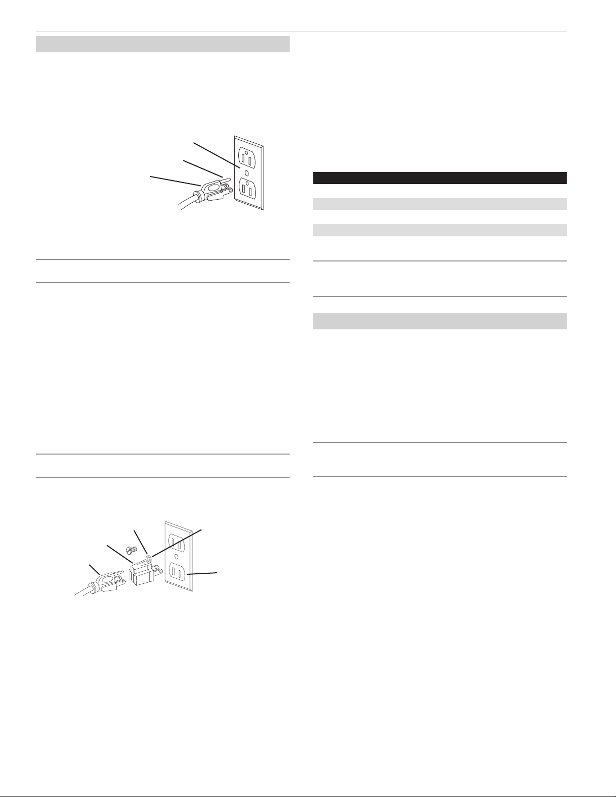
This tool is equipped with an approved 3-conductor cord rated at
150V and a three prong grounding type plug or your protection
against shock hazards.
• rounding plug should be plugged directly into a properly in-
stalled and grounded 3- prong grounding-type receptacle, as
shown (see Figure 12).
• Do not remove or alter grounding prong in any
manner. In the event of a malfunction or breakdown, grounding
provides a path of least resistance for electrical shock.
WARNING: Do not permit fingers to touch the terminals of plug
when installing or removing from outlet.
• Plug must be plugged into matching outlet that is properly in-
stalled and grounded in accordance with all local codes and or-
dinances. Do not modify plug provided. If it will not fit in outlet,
have proper outlet installed by a qualified electrician.
• Inspect tool cords periodically, and if damaged, have repaired
by an authorized service facility.
• reen (or green and yellow) conductor in cord is the grounding
wire. If repair or replacement of the electric cord or plug is nec-
essary, do not connect the green (or green and yellow) wire to a
live terminal.
Where a 2-prong wall receptacle is encountered, it must be re-
placed with a properly grounded 3-prong receptacle installed in
accordance with National Electric Code and local codes and
ordinances.
WARNING: This work should be performed by a qualified
electrician.
A temporary 3-prong to 2-prong grounding adapter (see Figure 13)
is available for connecting plugs to a two pole outlet if it is properly
grounded.
• Do not use a 3-prong to 2-prong grounding adapter unless per-
mitted by local and national codes and ordinances. (A 3-prong
to 2-prong grounding adapter is not permitted in Canada.)
Where permitted, the rigid green tab or terminal on the side of
the adapter must be securely connected to a permanent electri-
cal ground such as a properly grounded water pipe, a properly
grounded outlet box or a properly grounded wire system.
Many cover plate screws, water pipes and outlet boxes are not
properly grounded. To ensure proper ground, grounding means
must be tested by a qualified electrician.
EXTENSION CORDS
• The use of any extension cord will cause some drop in voltage
and loss of power.
• Wires of the extension cord must be of sufficient size to carry
the current and maintain adequate voltage.
• Use the table to determine the minimum wire size (A.W. .) ex-
tension cord.
• Use only 3-wire extension cords having 3-prong grounding
type plugs and 3-pole receptacles which accept the tool plug.
• If the extension cord is worn, cut, or damaged in any way, re-
place it immediately.
Cord Length inimum Wire Size A.W.G.
Up to 25 ft. 18
25 to 50 ft. 16
50 to 100 ft. 14
100 to 150 ft. 12
NOTE Using extension cords over 150 ft. long is not recommended.
WARNING: This machine must be grounded. To avoid electro -
cution or fire, any repairs to electrical system should be done only
by a qualified electrician, using genuine replacement parts.
OPERATION
The NORSE 14" Band Saw features welded steel frame construction
and a solid cast iron table surface to insure durability. It is designed
for cutting hard and soft woods. The saw is equipped with a miter
gauge for performing many different operations. A convenient
quick tensioning and comprehensive tracking mechanism makes
blade changing quick and easy. Saw also features a rip fence and
dust collection port.
SAFETY PRECAUTIONS
WARNING: Always observe the following safety precautions.•
Whenever adjusting or replacing any parts on the band saw turn,
switch off and remove plug from power source.
• Make sure the blade guides are positioned correctly.
• Use the appropriate blade for the workpiece that is being cut.
• Use a sharp blade. Replace dull blades or blades which are miss-
ing teeth.
• Make sure the blade is tensioned properly and going in the
right direction.
• Use the proper blade speed for the work.
• For optimum performance, do not stall the motor or reduce the
speed. Use the proper feed pressure.
• Secure the workpiece in a stable position.
• Check that all guards are attached.
• After turning the switch on, let the blade come to full speed.
• Keep hands away from the blade and all moving parts.
• Always wear eye protection or face shield.
• Always stop the band saw before removing scrap pieces from
table.
• Never attempt to saw stock that does not have a flat surface, un-
less a suitable support is used.
• Always hold material firmly and feed it into the blade at a mod-
erate speed.
• Always turn off the machine if the material is to be backed out
of an uncompleted cut.
Figure 12 – 3-Prong receptacle.
Properly grounded outlet.
rounding Prong
3-Prong Plug
Figure 13 – 2-Prong receptacle with adapter.
rounding Lug
Adapter
3-Prong Plug 2-Prong Re-
ceptacle
Make sure this is con-
nected to a known
grounded receptacle.
7
NORSE Operating Manual & Parts List 9683125
OPERATION (CONTINUED)
• Make sure that the blade tension and blade tracking are prop-
erly adjusted.
• Make “relief” cuts before cutting long curves.
• Release blade tension when the saw will not be used for a long
period of time.
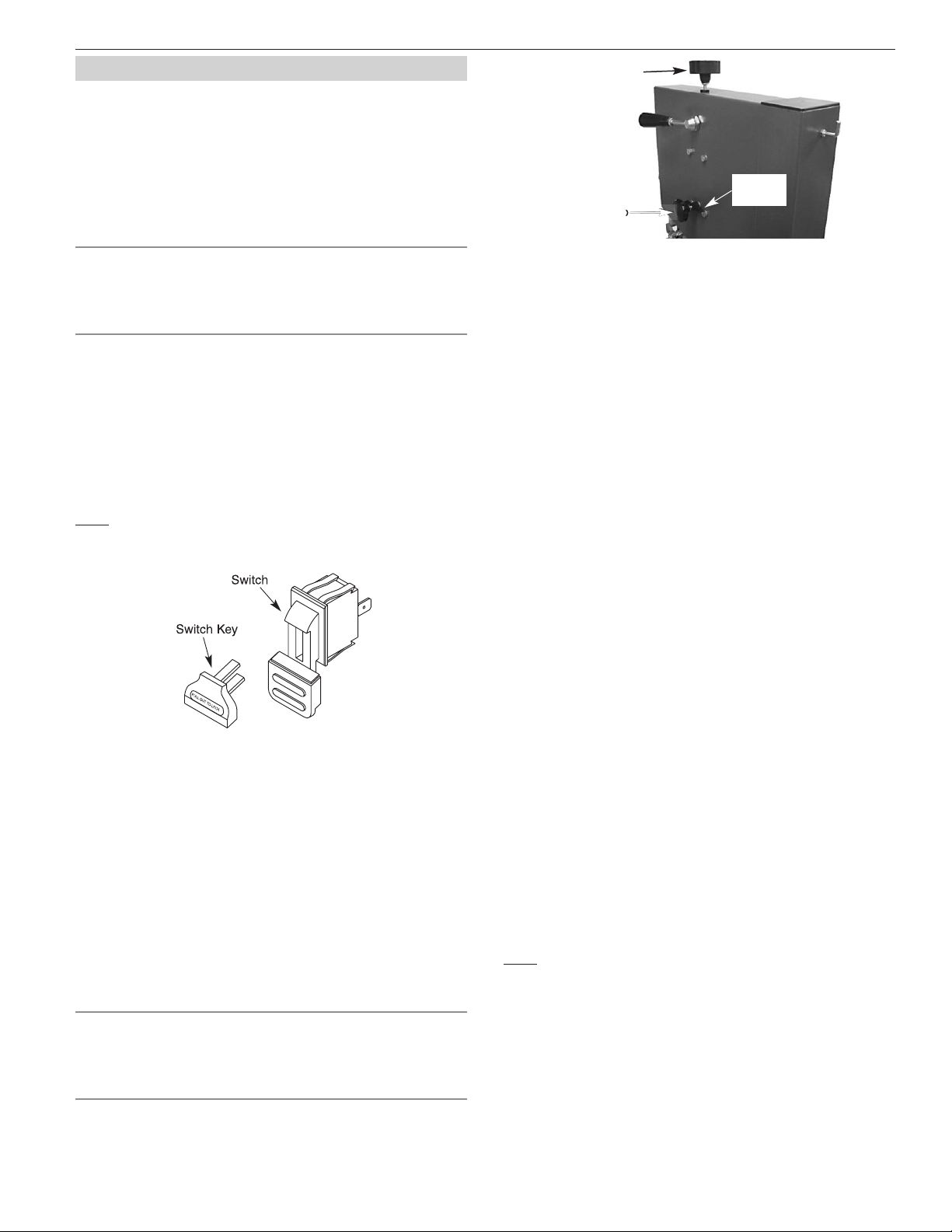
ON/OFF SWITCH
Refer to Figure 14.
WARNING: Before starting check if any part of your band saw is
missing, malfunctioning, has been damaged or broken, such as the
motor switch, or other operation control, a safety device or the
power cord, turn the band saw off and unplug it until the
particular part is properly repaired or replaced.
The ON/OFF switch is located on the left front of the saw column.
To turn saw ON, pull the switch to the up position. To turn saw OFF,
push the switch to the down position.
The saw can be locked from unauthorized use by locking the
switch. To lock the switch:
1. Turn the switch to OFF position and disconnect saw from power
source.
2. Pull the key out. The switch cannot be turned on with the key
removed.
NOTE: Should the key be removed from the switch at the ON posi-
tion, the switch can be turned off but cannot be turned on again.
• To replace key, slide key into the slot on switch until it snaps.
ADJUST ENTS
The blade tracking, tension and blade guides have been properly
adjusted at the factory. However, the adjustments may change
while the saw is in transit.
It is recommended to verify these adjustments before operating
saw.
CHANGING AND ADJUSTING THE SAW BLADE
This band saw is factory-equipped with a general-purpose wood
cutting blade; the saw blade is set prior to delivery.
To change the saw blade, the following procedure must be fol-
lowed:
WARNING: To avoid injury from unexpected starting, whenever
changing the saw blade or carrying out adjustments, switch the
band saw off and remove the power cord from the main outlet. To
avoid injury to hands when handling the saw blade, wear gloves
whenever necessary.
1. Remove the rip fence and the guide rail from the table.
2. Open the upper and lower doors by turning the door locking
knobs.
3. Loosen the tracking lock nut (See figure 15).
4. Loosen the blade tension by turning the blade tension knob on
the top of the upper wheel housing counterclockwise until the
saw blade has slackened (viewed from above) or turn blade ten-
sion quick release lever to the right. See Figures 15 and 10.
5. Remove the saw blade from the upper and lower wheels.
When fitting the new saw blade ensure the blade teeth are point-
ing downwards and towards you at the position where the saw
blade passes through the table.
6. Re-tension the new saw blade and check the saw blade tracking
by turning the upper wheel by hand.
The saw blade should run in the center of the band saw wheels. If
needed adjust the tracking of the saw blade. See "Tracking the Saw
Blade".
7. Tighten the tracking lock nut.
8. Replace the rip fence and the guide rail onto the table.
9. Close the upper and lower doors by turning the door locking
knobs before reconnecting the power supply.
TRACKING THE SAW BLADE
Set the tracking of the saw blade before setting the blade guides.
1. Once the saw blade is installed and tensioned, track the saw
blade by adjusting the tracking knob by hand (see Figure 15).
2. The saw blade should run in the center of the band saw wheels.
3. When the correct adjustment is achieved lock the tracking knob
with the lock nut.
SETTING THE CUTTING HEIGHT
The upper blade guide should be set as close as practical against
the workpiece.
1. To adjust this height, loosen the locking knob in the center of
the adjusting knob (See Figure 16).
2. Set the blade guide to the required height by turning the guide
post adjusting knob.
3. Tighten locking knob after setting.
ADJUSTING THE BLADE GUIDES
Refer to Figures 17 and 18.
NOTE: Upper and lower blade guides are adjusted in the same man-
ner.
1. To adjust the upper blade guides, first position the right and left
roller guides relative to the blade by loosening set screw (A)
and moving the guide carrier until both roller guides are ap-
proximately 1/16˝ behind the gullets of the saw blade. Tighten
set screw (A).
2. Set both roller guides to within 1/32˝ of the saw blade by loos-
ening the thumb screw (B) then turning shaft (C) at rear of
guide carrier. Do not set the roller guides too close as this will
adversely affect the life of the saw blade. Tighten thumb screws.
Figure 14 - ON/OFF switch and key.
Figure 15 - Saw blade adjustments.
Blade Tension Knob
Tracking Knob
Tracking
Lock Nut

8
NORSE Operating Manual & Parts List 9683125
OPERATION (CONTINUED)
3. Adjust the rear roller guide to be just clear of the back of the
saw blade by unlocking the set screw (D) located on rear of
guide carrier, adjust shaft (E), then lock set screw (D).
TILTING THE TABLE
For bevel cuts, the table tilts 0 through 45 degrees.
1. To tilt the table, loosen the locking handle on the table trun-
nion, set the table to the required angle by turning adjustment
knob (See Figure 19). Secure table in position by tightening
locking handle.
2. It is recommended to verify the correct angle setting using an
angle guide, or by making trial cuts in scrap wood. Adjust the in-
dicator accordingly by using a Phillips head screwdriver.
ADJUSTING THE RIP FENCE
Refer to Figure 20.
The locking pressure of the rip fence has been factory-set.
• The fence handle has a cam action, press down the handle to
clamp tightly to the table after setting rip fence to desired posi-
tion.
NOTE: The rip fence can be used on both sides of the blade. The rip
fence extrusion needs to be positioned on the side of the fence
body that is closest to the blade.
BLADE SPEED ADJUST ENT
Refer to Figure 21
WARNIN : Make certain that saw is disconnected from the power
source before attempting to change the blade speed.
1. Open lower housing door.
2. Loosen drive belt by turning handwheel clockwise.
3. Position belt on desired pulley of blade wheel and motor. Belt
must run on both front or both rear pulleys only.
4. Drive belt on front pulleys (nearest to blade wheel) results in
low blade speed.
5. Drive belt on rear pulleys (nearest to frame) results in high
blade speed.
6. Tighten drive belt by turning handwheel counterclockwise.
7. Close lower housing door.
PUSH STICK
• The push stick protects against accidental contact with the saw
blade.
• Always use the push stick when the distance between the saw
blade and rip fence is less than 5 inches.
• Hold the push stick at an angle of 25-30 degrees to the table
surface and guide workpiece through the blade.
• When the push stick is not in use, store it on the hook located at
the top rear of the saw frame.
BLADE SELECTION
• Blades vary depending on type of material, size of workpiece
and type of cut that is being performed.
• Characteristics which make blades different are width, thickness
and pitch.
BLADE WIDTH
• Width of blade describes distance from tip of a tooth to back of
blade.
• Width of blade affects rigidity of blade. A wider blade wanders
less and produces a straighter cut.
• Width of blade also limits the smallest radius which can be cut.
A 1/4˝ wide blade can cut about a 1/2˝ radius.
BLADE THICKNESS
• Blade thickness describes the distance between sides of blade.
A thicker blade has more rigidity and stronger teeth.
• A narrow thick blade is used to cut curves while a wide thin
blade is used to make long, straight cuts.
Figure 18 - Adjusting blade guides.
Rear
uide
uide Carrier
(B)
(E)
(D)
Figure 19 - Tilting the table.
Adjusting Knob
Locking Handle
Indicator
Figure 20 - Adjusting rip fence.
Fence
Extrusion
Fence Body
Figure 21 - Changing the blade speed.
Handwheel
Brush
Drive
Belt

OPERATION (CONTINUED)
BLADE PITCH
• Pitch describes number of teeth per inch or tooth size. A blade
with more teeth per inch produces a smoother cut.
• The type of material being cut determines number of teeth
which should be in contact with work.
• For soft materials, the proper blade has between 6 to 8 teeth
per inch.
• When cutting hard materials, where shocking is more detrimen-
tal, use a blade with 8 to 12 teeth per inch.
• There should always be at least three teeth in contact with cut
to avoid shocking blade.
• lade shocking occurs when pitch is too large and blade tooth
encounters too much material. This can strip teeth from blade.
• Blade manufacturers are prepared to supply information about
blades for specific applications.
TYPE OF CUT
• Contour cutting is done by guiding workpiece freehanded to
produce curved shapes.
• Beveled cutting is done by tilting saw table and using proper
work guide method.
• Regardless of which work guiding method is used, a workpiece
which overhangs table by more than 5˝ needs proper support.
CONTOUR SAWING
• When contour sawing, use both hands to keep workpiece flat
against table and guided along desired path.
• Avoid positioning hands in line with blade. If hands slip, they
could contact blade.
• Try to stand to front of the saw and use hands over the portion
of table which is to right of blade and before cut.
• Cut small corners by sawing around them. Saw to remove scrap
until desired shape is obtained.
BEVEL CUTTING
Perform bevel cutting by tilting table to desired degree.
1. Unlock table by loosening locking handle located on the back-
side of the unit.
2. Tilt table to desired position.
3. Lock table in position by tightening locking handle.
ITER GAUGE
Use miter gauge for securing and holding workpiece at desired
angle to produce angled cuts. Use scale to adjust gauge to desired
angle.
WARNING: Never use miter gauge and rip fence at the same
time. The blade might bind in the workpiece. Operator could be
injured and/or workpiece could be damaged.
BLADE CLEANING BRUSH
Refer to Figure 21.
Make sure that brush is in contact with blade to properly remove
foreign particles from drive wheel.
MAINTENANCE
Steps required to keep the saw in optimum operating condition
have been described under “Operating Instructions.” The Safety
Precautions should be performed before operation.
For proper maintenance:
• Keep saw clean and dry. Sweep off spots where chips have col-
lected.
• Lubricate the unpainted surfaces with a light application of
medium consistency machine oil to prevent corrosion after
cleaning.
• Replace dull blades and blades from which teeth have been
stripped. A clean saw with a sharp blade will yield the best cut.
• Internal parts of the band saw have been completely lubricated
at the factory and do not need to be relubricated.
WARNING: Make certain that the saw is disconnected from the
power source before attempting to service or remove any
component.
9
NORSE Operating Manual & Parts List 9683125

The machine does not work when
switched on.
The saw blade does not move with
the motor running.
The saw blade does not cut in a
straight line.
The saw blade does not cut, or cuts
very slowly.
Sawdust builds up inside the
machine.
Sawdust inside the motor housing.
The machine does not cut at 45 or 90
degrees.
The saw blade cannot be properly
positioned on the wheels.
1. No power supply.
2. Defective switch.
3. Defective motor.
1. The blade tension knob has not been tight-
ened.
2. The blade has come off one of the wheels.
3. The saw blade has broken.
4. The drive belt has snapped.
1. Rip fence for cutting not used.
2. Feed rate too fast.
3. The blade teeth are dull or damaged.
4. Blade guides not suitably adjusted.
1. The teeth are dull, caused by cutting hard
material or long use.
2. The saw blade was fitted the wrong way on
the band saw.
This is normal
This is normal
1. The table is not at right angles to the blade.
2. The saw blade is dull or too much pressure
was put on the workpiece.
1. The wheels are not in alignment or
defective bearing.
2. The blade tracking knob hasn’t been
properly adjusted.
3. Inferior saw blade.
1. Check the cable for breakage.
2. Replace the lock switch.
3. Replace the motor.
1. Switch off the motor, tighten the blade tension
knob.
2. Open the doors and check
3. Replace the blade.
4. Replace the belt.
1. Use a rip fence.
2. Put light pressure on the workpiece. Make sure the
saw blade does not bend.
3. Try a new saw blade.
4. Adjust the blade guides (see OPERATION
instructions).
1. Replace the saw blade, use a 6 T.P.I. saw blade for
wood and soft material. Use a 14 T.P.I. saw blade for
harder materials. A 14 T.P.I. saw blade always cuts
slower due to the finer teeth and the slower cut-
ting performance.
2. Fit the saw blade correctly.
Clean the machine regularly. Open the doors and
remove the sawdust with a vacuum cleaner.
Clean the ventilating slots of the motor with a vac-
uum cleaner. From time to time remove the sawdust
to prevent it from being drawn into the housing.
1. Adjust the table.
2. Replace the saw blade or put less pressure on the
workpiece.
1. Replace bearing.
2. Adjust the blade tracking knob (See OPERATION
instructions).
3. Replace the saw blade.
TROUBLESHOOTING
10
NORSE Operating Manual & Parts List 9683125
SY PTO POSSIBLE CAUSE(S) CORRECTIVE ACTION
11
NORSE Operating Manual & Parts List 9683125
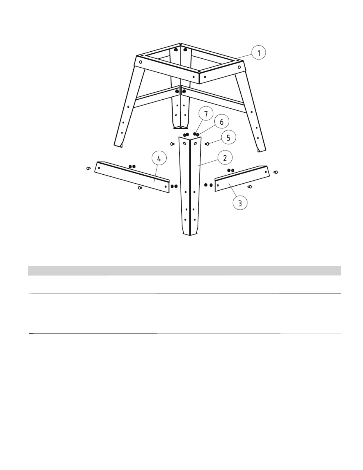
REPLACEMENT PARTS LIST FOR XXX
1 Mounting plate 9643002.01 1
2 Leg 9643003.01 4
3 Short connection plate 9643004.01 2
4 Long connection plate 9643005.01 2
5 Carriage bolt, M8×16 * 16
6 Washer M8 * 16
7 Nut M8 * 16
Ref.
No. Description Part Number: Qty.
(∆) Not shown.
(N/A) Not available as repair part.
(*) Standard hardware item, available locally.
Figure 24 - Replacement Parts Illustration For Stand
12
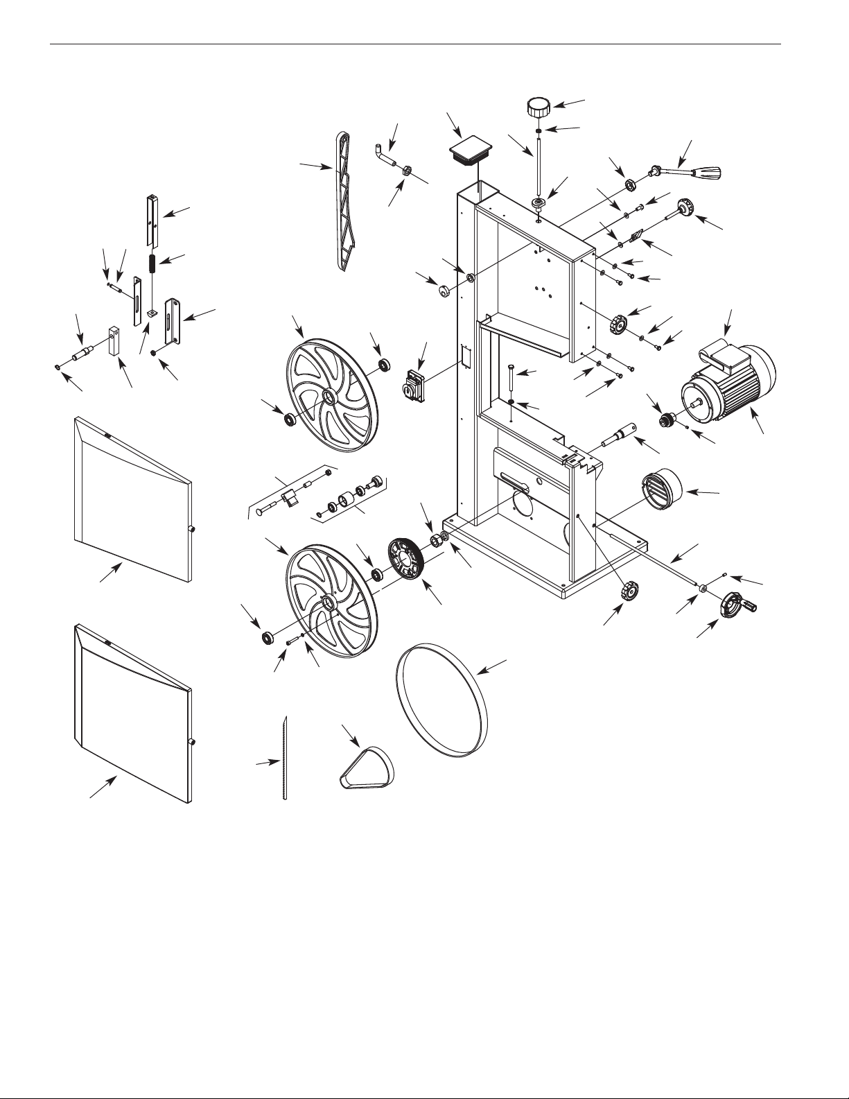
NORSE Operating Manual & Parts List 9683125
2
45
46
47
22
48
43
43
50 29
49
1
53
52
51
31
39
40
34
38
37
36
32
29
31
30
29
41
18
35
34 33
54
30
29 28
27
25
18
26
21
22
20
19 18
17
43
42
43
44
24
23
15
16
14
13
11
10
4
35
8
6
7
9
12
Figure 22 - Replacement Parts Illustration for Frame and Drive

13
NORSE Operating Manual & Parts List 9683125
1 Lower Door Assembly 9636492.00 1
2 Upper Door Assembly 9636493.00 1
3 3AMI-18 Retaining Ring 9606169.00 2
4 Upper Wheel Shaft 9636496.00 1
5 Tension Block 9636497.00 1
6 8-1.25mm Flange Nut 9620330.00 4
7 uide Plate 9636498.00 2
8 Nut 9636499.00 1
9 Spring 9636500.00 1
10 Shaft 9636501.00 1
11 3CMI-8 Retaining Ring 9608323.00 2
12 Tension Bracket Frame 9636503.00 1
13 Push Stick 9636495.00 1
14 Hook 9636502.00 1
15 6-1.0mm Hex Nut * 1
16 Cap 9636506.00 1
17 Tension Knob 9636504.00 1
18 8-1.25mm Jam Nut 9602293.00 3
19 Threaded Rod 9636505.00 1
20 Bushing 9636507.00 1
21 Tension Release Handle 9636508.00 1
22 20-1.5mm Hex Nut 9636509.00 2
23 Spacer 9636510.00 1
24 Cam 9636511.00 1
25 8-1.25 x 16mm Hex Head Bolt * 8
26 8mm Flat Washer * 8
27 Tracking Knob 9636512.00 1
28 Wing Nut 9636513.00 1
29 6mm Flat Washer * 9
30 6-1.0 x 10mm Hex Head Bolt * 4
31 Door Locking Knob 9636514.00 2
32 6-1.0 x 16mm Socket Head Bolt * 2
33 Motor 9636515.00 1
34 6-1.0 x 6mm Set Screw * 2
35 Motor Pulley 9636516.00 1
36 Lower Wheel Shaft 9636517.00 1
37 Dust Port 9636518.00 1
38 Shaft 9636519.00 1
39 Collar 9636520.00 1
40 Belt Tension Hand-wheel Assembly 9636521.00 1
41 8-1.25 x 80mm Hex Head Bolt 9619029.00 1
42 Switch Assembly 9636522.00 1
43 Bearing 6202zz 9601540.00 4
44 Upper Wheel 636494.00 1
45 Brush Assembly 9636523.00 1
46 Belt Tension Drum Assembly 9636524.00 1
47 20mm Lock Washer * 1
48 Drive Pulley 9636525.00 1
49 Lower Wheel 9636526.00 1
50 6-1.0 x 35mm Socket Head Bolt * 3
51 Tire 9636527.00 2
52 Drive Belt 9636528.00 1
53 Blade 9636529.00 1
54 Capacitor 9636530.00 1
REPLACEMENT PARTS LIST FOR FRAME AND DRIVE
Ref.
No. Description Part No. Qty.
Ref.
No. Description Part No. Qty.
(∆) Not shown.
(N/A) Not available as repair part.
(*) Standard hardware item, available locally.

14
NORSE Operating Manual & Parts List 9683125
Figure 23 - Replacement Parts Illustration For Table
11
15
13
12
16 17 19
18
14 10
9
8
20
7
65
4
3
21
22
21
33
41
59
45 44
43
42 38
40 37
23
35 23
34
39
33
32
31
30 29
26
27
23
24
25
28
19
12
17
15
13
18
14
16
46
47
36
62
61
63
55
52
51
50
48
49
53
54
56
57
58 59
60

15
NORSE Operating Manual & Parts List 9683125
1 4.8 x 16mm Tap Screw 9631663.00 2
2 Plate 9636427.00 1
3 Rack 9636428.00 1
4 uide Post 9636429.00 1
5 Pressure Plate 9636430.00 1
6 Pin 9636431.00 2
7 Rack ear and Shaft 9636432.00 1
8 uide Block Pin 9636531.00 1
9 uide Carrier 9636433.00 1
10 4.8 x 22mm Tap Screw 9620650.00 2
11 Sliding uard 9636434.00 1
12 Spacer 9636435.00 2
13 Threaded Rod 9636436.00 2
14 uide Shaft 9636437.00 4
15 Adjusting Nut 9636438.00 2
16 Bearing 627zz 9617847.00 6
17 uide Block 9636439.00 2
18 Shaft 9636440.00 2
19 Thumb Screw 9636441.00 4
20 uide Adjusting Knob Assembly 9636442.00 1
21 Table 9636443.00 1
22 Table Insert 9636444.00 1
23 8mm Flat Washer * 6
24 Wing Bolt 9636445.00 4
25 Fence Rail Left Cap 9636446.00 1
26 Fence Rail 9636447.00 1
27 Fence Rail Right Cap 9636448.00 1
28 Scale 9636449.00 1
29 8-1.25mm Hex Nut * 1
30 Knob 9636450.00 1
31 8-1.25mm Jam Nut 9602293.00 1
32 Shaft 9636451.00 1
33 ear 9636452.00 2
34 Locking Handle 9636453.00 1
35 Spacer 9636454.00 1
36 Lower Blade uard 9636462.00 1
37 Trunnion 9636455.00 2
38 Angle Scale 9636456.00 1
39 Spacer 9636457.00 1
40 Trunnion Bracket 9636458.00 1
41 Bolt 9636660.00 2
42 Indicator 9636459.00 1
43 4-0.7 x 6mm Pan Head Screw * 1
44 6-1.0 x 6mm Socket Head Bolt * 4
45 8-1.25 x 16mm Socket Head Bolt * 4
46 Locking Pin 9636460.00 1
47 Lower uide Seat 9636461.00 1
48 Handle Assembly 9636532.00 1
49 Cam 9636533.00 1
50 3.5 x 9.5 Tap Screw 9631585.00 2
51 Pressure Plate 9636534.00 1
52 Fence Carrier 9636535.00 1
53 Shaft 9636537.00 1
54 Lens 9636538.00 1
55 Plate 9636539.00 1
56 Cap 9636540.00 2
57 6-1.0 x 35mm Socket Head Bolt * 2
58 Wing Nut 9636541.00 2
59 6mm Flat Washer * 5
60 Fence Bracket 9636542.00 1
61 6-1.0 x 45mm Carriage Bolt 9636659.00 2
62 Plate 9636543.00 1
63 Fence 9636544.00 1
∆ Miter auge 9636546.00 1
∆ Complete Rip Fence Assy. 9636545.00 1
(Ref. Nos. 48-63
REPLACEMENT PARTS LIST FOR TABLE
Ref.
No. Description Part No. Qty.
Ref.
No. Description Part No. Qty.
(∆) Not shown.
(N/A) Not available as repair part.
(*) Standard hardware item, available locally.

NORSE Operating Manual & Parts List 9683125
NORSE - a C.H. Hanson brand
2000 N. Aurora Rd., Naperville, IL 60563 U.S.A.
or call: 1-800-827-3398
NORSE by C.H. Hanson warrants their products to be free of defects in material or workmanship. This
warranty does not cover defects due directly or indirectly to misuse, abuse, normal wear and tear, failure
to properly maintain the product, heated, ground or otherwise altered, or used for a purpose other than
that for which it was intended.
The warranty does not cover expendable and/or wear part (i.e. v-belts, screws, abrasives, jaws), damage to
tools arising from alteration, abuse or use other than their intended purpose, packing and freight. The
duration of this warranty is expressly limited to the terms noted below beginning from the date of
delivery to the original user.
The NORSE branded items carry the following warranties on parts:
All NORSE branded Tools and Accessories 1 YEAR
The obligation of NORSE by C.H. Hanson is limited solely to the repair or replacement, at our option, at its
factory or authorized repair agent of any part that should prove inoperable. Purchaser must lubricate and
maintain the product under normal operating conditions at all times. Prior to operation become familiar
with product and the included materials, i.e. warnings, cautions and manuals.
Failure to follow these instructions will void the warranty.
This warranty is the purchaser's exclusive remedy against C. H. Hanson for any inoperable parts in its
product. Under no circumstances is C. H. Hanson liable for any direct, indirect, incidental , special or
consequential damages including loss of profits in any way related to the use or inability to use our
products. This warranty gives you specific legal rights which may vary from state to state.
SERVICE & REPAIR
1. If a NORSE product requires a repair or warranty service DO NOT return the product to
the place of purchase.
2. All warranty related work must be evaluated and approved by NORSE.
3. Prior to returning any item the user must obtain factory approval and a valid R A number.
4. For instructions and R A number call toll free (800) 827-3398.
NORSE WARRANTY
18-0307
Table of contents
Other CH Hanson Saw manuals


Popular Saw manuals by other brands

Scheppach
Scheppach HM120L Original instruction manual

Craftsman
Craftsman 22299 owner's manual

Milwaukee
Milwaukee M18 CSX Operator's manual

Axminster
Axminster Professional AP2552B instruction manual

MK Diamond Products
MK Diamond Products MK-660 SERIES Owner's manual & operating instructions

EINHELL Expert
EINHELL Expert TE-TS 1825/1 U Original operating instructions


