CH Hanson NORSE 9683412 Instructions for use

9643342.01 0518
Model 9683412
Please read and save these instructions. Read carefully before attempting to
assemble, install, operate or maintain the product described.
Protect yourself and others by observing all safety information. Failure to comply
with instructions could result in personal injury and/or property damage!
Retain instructions for future reference.
10˝
T ble S w
Oper ting Instructions & P rts M nu l

Here are the guidelines to help you understand the symbols used in this guide.
DANGER!
Indicates a potentially hazardous situation which could result in death or serious injury.
WARNING!
Indicates a situation which could result in death or serious injury
CAUTION!
Indicates a potentially hazardous situation which could result in mild to moderate injury
NOTICE:
When used without the Safety Alert symbol, this indicates a potentially hazardous
situation which, if not avoided, can result in property damage
TABLE OF CONTENTS
SAFETY GUIDELINES
Be sure to read and understand this manual for your safety. When using this product, it is
important to read and understand this information. It will protect you and help prevent any
problems
• KNOW YOUR POWER TOOL. Read the operator’s manual carefully. Learn the saw’s
tool.
• GUARD AGAINST ELECTRICAL SHOCK BY PREVENTING BODY CONTACT
WITH GROUNDED SURFACES. For example, pipes, radiators, ranges, refrigerator
enclosures.
• KEEP GUARDS IN PLACE and in good working order.
• REMOVE ADJUSTING KEYS AND WRENCHES. Form a habit of checking to see
that keys and adjusting wrenches are removed from tool before turning it on.
• KEEP WORK AREA CLEAN. Cluttered areas and benches invite accidents. DO NOT
leave tools or pieces of wood on the saw while it is in operation.
• DO NOT USE IN DANGEROUS ENVIRONMENTS. Do not use power tools in damp
or wet locations or expose to rain. Keep the work area well lit.
• KEEP CHILDREN AND VISITORS AWAY. All operators should wear safety glasses
and be kept a safe distance from work area. Do not contact tool or extension cord
while operating.
• MAKE WORKSHOP CHILDPROOF with padlocks and master switches, or by
removing starter keys.
2
SAFETY GUIDELINES ............................................2-7
FEATURES ......................................................8-9
ASSEMBLY & ADJUSTMENTS ..................................10-17
OPERATIONS ..................................................18-24
BLADE ADJUSTMENTS.........................................25-27
MAINTENANCE ................................................28-29
PARTS LIST ...................................................30-31
WARRANTY ......................................................32

SAFETY GUIDELINES
• DON’T FORCE TOOL.,WZLOOGRWKHMREEHWWHUDQGVDIHUDWWKHIHHGUDWHIRUZKLFKLW
ZDVGHVLJQHG
• USE RIGHT TOOL.'RQ¶WIRUFHWKHWRRORUDWWDFKPHQWWRGRDMRELWZDVQRWGHVLJQHG
IRU'RQ¶WXVHLWIRUDSXUSRVHQRWLQWHQGHG
• USE THE PROPER EXTENSION CORD.0DNHVXUH\RXUH[WHQVLRQFRUGLVLQJRRG
FRQGLWLRQ8VHRQO\DFRUGKHDY\HQRXJKWRFDUU\WKHFXUUHQW\RXUSURGXFWZLOOGUDZ
$QXQGHUVL]HGFRUGZLOOFDXVHDGURSLQOLQHYROWDJHUHVXOWLQJLQORVVRISRZHUDQG
RYHUKHDWLQJ$ZLUHJDXJHVL]H$:*RIDWOHDVWLVUHFRPPHQGHGIRUDQ
H[WHQVLRQFRUGIHHWRUOHVVLQOHQJWK,ILQGRXEWXVHWKHQH[WKHDYLHUJDXJH7KH
VPDOOHUWKHJDXJHQXPEHUWKHKHDYLHUWKHFRUG
• DRESSPROPERLY.'RQRWZHDUORRVHFORWKLQJJORYHVQHFNWLHVRUMHZHOU\7KH\
FDQJHWFDXJKWDQGGUDZ\RXLQWRPRYLQJSDUWV5XEEHUJORYHVDQGQRQVNLGIRRWZHDU
DUHUHFRPPHQGHGZKHQZRUNLQJRXWGRRUV$OVRZHDUSURWHFWLYHKDLUFRYHULQJWR
FRQWDLQORQJKDLU
• ALWAYS WEAR SAFETY GLASSES WITH SIDE SHIELDS.(YHU\GD\H\HJODVVHV
RQO\KDYHLPSDFWUHVLVWDQWOHQVHVWKH\DUH127VDIHW\JODVVHV
• SECUREWORK.8VHFODPSVRUDYLVHWRKROGZRUNZKHQSUDFWLFDO,W¶VVDIHUWKDQ
XVLQJ\RXUKDQGDQGIUHHVERWKKDQGVWRRSHUDWHWRRO
• DON’TOVERREACH..HHSSURSHUIRRWLQJDQGEDODQFHDWDOOWLPHV
• MAINTAIN TOOLS WITH CARE..HHSWRROVVKDUSDQGFOHDQIRUEHWWHUDQGVDIHU
SHUIRUPDQFH)ROORZLQVWUXFWLRQVIRUOXEULFDWLQJDQGFKDQJLQJDFFHVVRULHV
• DISCONNECTTOOLS.:KHQQRWLQXVHEHIRUHVHUYLFLQJRUZKHQFKDQJLQJ
DWWDFKPHQWVEODGHVELWVFXWWHUVHWFDOOWRROVVKRXOGEHGLVFRQQHFWHG
• AVOIDACCIDENTALSTARTING.%HVXUHVZLWFKLVRIIZKHQSOXJJLQJLQDQ\WRRO
• USERECOMMENDEDACCESSORIES.&RQVXOWWKHLQVWUXFWLRQPDQXDOIRU
UHFRPPHQGHGDFFHVVRULHV8VHRILPSURSHUDFFHVVRULHVPD\ULVNLQMXU\
• NEVER STAND ON TOOL.6HULRXVLQMXU\FRXOGRFFXULIWKHWRROLVWLSSHGRULIWKH
FXWWLQJWRROLVXQLQWHQWLRQDOO\FRQWDFWHG
• CHECK DAMAGED PARTS.%HIRUHIXUWKHUXVHRIWKHWRRODJXDUGRURWKHUSDUWWKDW
LVGDPDJHGVKRXOGEHFDUHIXOO\FKHFNHGWRGHWHUPLQHWKDWLWZLOORSHUDWHSURSHUO\
DQGSHUIRUPLWVLQWHQGHGIXQFWLRQ&KHFNIRUDOLJQPHQWRIPRYLQJSDUWVELQGLQJRI
PRYLQJSDUWVEUHDNDJHRISDUWVPRXQWLQJDQGDQ\RWKHUFRQGLWLRQVWKDWPD\DIIHFW
LWVRSHUDWLRQ$JXDUGRURWKHUSDUWWKDWLVGDPDJHGPXVWEHSURSHUO\UHSDLUHGRU
UHSODFHGE\DQDXWKRUL]HGVHUYLFHFHQWHUWRDYRLGULVNRISHUVRQDOLQMXU\
• USE THE RIGHT DIRECTION OF FEED.2QO\IHHGZRUNLQWRDEODGHRUFXWWHU
DJDLQVWWKHGLUHFWLRQRIURWDWLRQRIEODGHRUFXWWHU
• NEVER LEAVE TOOL RUNNING UNATTENDED. TURN THE POWER OFF.'RQ¶W
OHDYHWRROXQWLOLWFRPHVWRDFRPSOHWHVWRS
• PROTECTYOURLUNGS.:HDUDIDFHRUGXVWPDVNLIWKHFXWWLQJRSHUDWLRQLVGXVW\
• PROTECTYOURHEARING.:HDUKHDULQJSURWHFWLRQGXULQJH[WHQGHGSHULRGVRI
operation.
• DO NOT ABUSE CORD.1HYHU\DQNFRUGWRGLVFRQQHFWIURPUHFHSWDFOH.HHSFRUG
DZD\IURPKHDWRLODQGVKDUSHGJHV
3

SAFETY GUIDELINES
SPECIFIC SAFTEY RULES
• NEVERperform any operation “freehand” which means using only your hands to
support or guide the workpiece. Always use either the rip fence or miter gauge to
position and guide the work.
• NEVERstand or have any part of your body in line with the path of the saw blade.
• NEVERreach behind, over, or within three inches of the blade or cutter with either
hand for any reason.
• MOVE THE RIP FENCE out of the way when cross cutting.
• DO NOT USE THE MITER GAUGE AND RIP FENCE during the same operation.
• NEVERuse rip fence as cutoff gauge when cross cutting.
• NEVER
disconnecting the saw from the power source.
• PROVIDEADEQUATESUPPORTto the rear and sides of the saw table for wide or
long work pieces.
• AVOIDKICKBACKS(work thrown back toward you) by:
a) Keeping blade sharp.
b) Keeping rip fence parallel to the saw blade.
c) Keeping riving knife, anti-kickback pawls, and blade guard in place and
operating.
d) Not releasing the work before it is pushed all the way past the saw blade using a
push stick.
e) Not ripping work that is twisted, warped or does not have a straight edge to guide
along the fence.
• WHEN OPERATING A POWER TOOL OUTSIDE, USE AN OUTDOOR EXTENSION
CORD MARKED “W-A” OR “W”. These cords are rated for outdoor use and reduce
the risk of electric shock.
• KEEP BLADES CLEAN, SHARP, AND WITH SUFFICIENT SET. Sharp blades
minimize stalling and kickback.
• KEEP HANDS AWAY FROM CUTTING AREA. Keep hands away from blades. Do
not reach underneath work, around or over the blade while blade is rotating. Do not
attempt to remove cut material when blade is moving.
4

SAFETY GUIDELINES
• IF THE POWER SUPPLY CORD IS DAMAGED,LWPXVWEHUHSODFHGRQO\E\WKH
PDQXIDFWXUHURUE\DQDXWKRUL]HGVHUYLFHFHQWHUWRDYRLGULVN
• AVOID AWKWARD OPERATIONS AND HAND POSITIONS where a sudden slip
FRXOGFDXVH\RXUKDQGWRPRYHLQWRWKHFXWWLQJWRRO
• USE ONLY RECOMMENDED ACCESSORIES listed in this manual or addendums.
8VHRIDFFHVVRULHVWKDWDUHQRWOLVWHGPD\FDXVHWKHULVNRISHUVRQDOLQMXU\
Instructions for safe use of accessories are included with the accessory.
• MAKE SURE THE WORK AREA HAS AMPLE LIGHTINGWRVHHWKHZRUNDQGWKDW
QRREVWUXFWLRQVZLOOLQWHUIHUHZLWKVDIHRSHUDWLRQ%()25(SHUIRUPLQJDQ\ZRUNXVLQJ
WKHWDEOHVDZ
• ALWAYS TURN OFF SAWEHIRUHGLVFRQQHFWLQJWRDYRLGDFFLGHQWDOVWDUWLQJZKHQ
UHFRQQHFWLQJWRSRZHUVXSSO\
• ONLY USE BLADESZLWKLQWKHWKLFNQHVVUDQJHVWDPSHGRQWKHVDZEODGHDQGRQ
instruction manual.
• THISTOOLVKRXOGKDYHWKHIROORZLQJPDUNLQJV
D:HDUH\HSURWHFWLRQ
E8VHVDZEODGHJXDUGDQGULYLQJNQLIHIRUHYHU\RSHUDWLRQIRUZKLFKLWFDQEH
XVHGLQFOXGLQJDOOWKURXJKVDZLQJ
F.HHSKDQGVRXWRIWKHOLQHRIVDZEODGH
G8VHDSXVKVWLFNZKHQUHTXLUHG
H3D\SDUWLFXODUDWWHQWLRQWRLQVWUXFWLRQVRQUHGXFLQJULVNRINLFNEDFN
I'RQRWSHUIRUPDQ\RSHUDWLRQIUHHKDQG
J1HYHUUHDFKDURXQGRURYHUWKHVDZEODGH
K1HYHURSHUDWHVDZRQÀRRURUEHORZZDLVWKHLJKW
• NEVER CUT MORE THAN ONE PIECE OF MATERIAL AT A TIME.
• SAVE THESE INSTRUCTIONS.5HIHUWRWKHPIUHTXHQWO\DQGXVHWRLQVWUXFWRWKHU
users. If you loan someone this tool, loan them these instructions also.
5
Specifications
Blade Arbor: 5/8" Cutting Range: 0º - 45º
Blade Diameter: 10" 24t Cutting Depth At 0º: 3-1/2"
Blade Tilt: 0º - 45º Cutting Depth At 45º: 2-1/4"
Rating: 120v, Ac Only, 60 Hz Table Size: 25" x 19"
Input: 15 A 6' Cord With Ul Plug
No Load Speed: 5,000 Rpm
ELECTRICAL
All electrical connections must be
performed by a qualified electrician.
Power Source
Connect sander to a supply circuit protected by a circuit breaker or time-delay fuse.
The motor is designed for operation on the voltage and frequency specified. Normal loads will
be handled safely on voltages not more than 10% above or below the specified voltage.
Running the unit on voltages which are not within the range may cause overheating and motor
burn-out. Heavy loads require that the voltage at motor terminals be no less than the voltage
specified. Power supply to the motor is controlled by a single pole locking rocker switch.
Remove the key to prevent unauthorized use.
Grounding Instructions
Improper connection of equipment grounding conductor can result
in the risk of electrical shock. Equipment should be grounded
while in use to protect operator from electrical shock.
Check with a qualified electrician if grounding instructions are not understood or if in doubt as to
whether the tool is properly grounded.
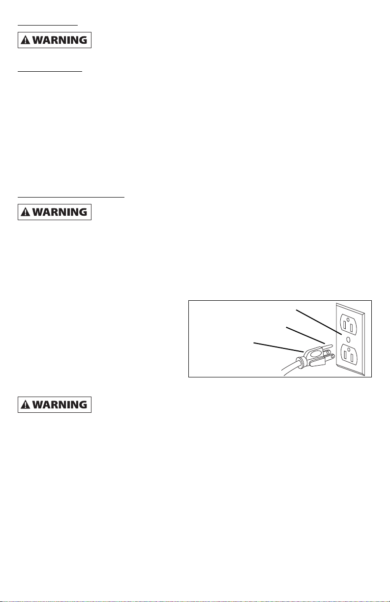
This tool is equipped with an approved 3-conductor cord rated at 300V and a 3-prong
grounding type plug for your protection against shock hazards.
Grounding plug should be plugged directly
into a properly installed and grounded 3-
prong grounding-type receptacle, as shown.
Do not remove or alter grounding prong in
any manner. In the event of a malfunction or
breakdown, grounding provides a path of
least resistance for electrical shock.
Do not permit fingers to touch the terminals of plug when installing
or removing from outlet.
Plug must be plugged into matching outlet that is properly installed and grounded in
accordance with all local codes and ordinances. Do not modify plug provided. If it will not fit in
outlet, have proper outlet installed by a qualified electrician.
Inspect tool cords periodically, and if damaged, have repaired by an authorized service facility.
Green (or green and yellow) conductor in cord is the grounding wire. If repair or replacement of
the electric cord or plug is necessary, do not connect the green (or green and yellow) wire to a
live terminal.
Where a 2-prong wall receptacle is encountered, it must be replaced with a properly grounded
3-prong receptacle installed in accordance with National Electric Code and local codes and
ordinances.
3-Prong recept cle.
Properly Grounded Outlet
Grounding Prong
3-Prong Plug
6

This work should be performed
by a qualified electrician.
A temporary 3-prong to 2-prong
grounding adapter is available for
connecting plugs to a two pole outlet if
it is properly grounded.
Do not use a 3-prong to 2-prong
grounding adapter unless permitted by
local and national codes and
ordinances.
(A 3-prong to 2-prong grounding adapter is not permitted in Canada.) Where permitted, the rigid
green tab or terminal on the side of the adapter must be securely connected to a permanent
electrical ground such as a properly grounded water pipe, a properly grounded outlet box or a
properly grounded wire system.
any cover plate screws, water pipes and outlet boxes are not properly grounded. To ensure
proper ground, grounding means must be tested by a qualified electrician.
Extension Cords
• The use of any extension cord will cause some drop in voltage and loss of power.
• Wires of the extension cord must be of sufficient size to carry the current and maintain
adequate voltage.
• Use the table to determine the minimum wire size (A.W.G.) extension cord.
• Use only 3-wire extension cords having 3-prong grounding type plugs and 3-pole
receptacles which accept the tool plug.
• If the extension cord is worn, cut or damaged in any way, replace it immediately.
Extension Cord Length nd G uge (120V
Len th Wire Size A.W.G.
Up to 25 ft 18
25 – 50 ft 16
NOTE: Using extension cords over 50 ft. long is not recommended.
2-Prong recept cle with d pter.
Grounding Lug
Adapter
3-Prong Plug
2-Prong
Receptacle
ake sure this is
connected to a
known grounded
receptacle.
7
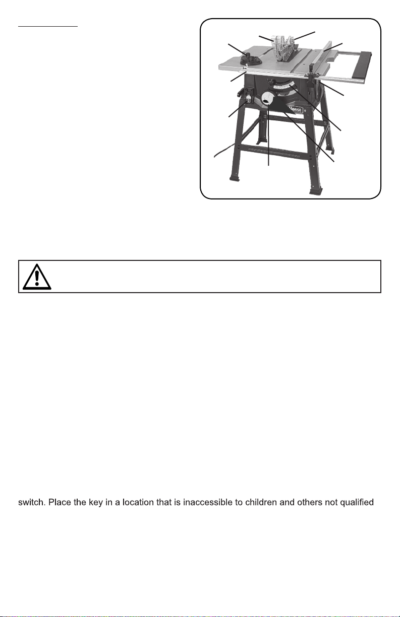
HEIGHT/
BEVEL
ADJUSTING
HANDWHEEL
BEVEL
LOCKING
LEVER
BEVEL
SCALE
SWITCH
SCALE
MITER
GAUGE
BLADE
GUARD
RIP FENCE
ANTI-
KICKBACK
PAWLS
LOCKING
LEVER
8
FEATURES
KNOW YOUR TABLE SAW
See Figure 2. The safe use of this
product requires an understanding of
the information on the tool and in this
operator’s manual, as well as a knowledge
of the project you are attempting. Before
use of this product, familiarize yourself with
all operating features and safety rules.
ANTI-KICKBACK PAWLS - Kickback is a
hazard in which the workpiece is thrown
back toward the operator. The teeth on
the removable anti-kickback pawls point
away from the workpiece. If the workpiece
should be pulled back toward the operator,
the teeth dig into the wood to help prevent
or reduce the possibility of kickback.
BEVEL SCALE - The easy-to-read scale
on the front of the cabinet shows the exact blade angle.
BLADE - This saw is provided with a 24-tooth, 10 in. carbide blade. The blade is raised
and lowered with the height/bevel adjusting handwheel. Bevel angles are locked with the
bevel locking lever.
BLADE GUARD - Always keep the removable blade guard down over the saw blade for
through-sawing cuts. BEVEL LOCKING LEVER - This lever, placed just under the saw
table surface on the front of the cabinet, locks the angle setting of the blade.
HEIGHT/BEVEL ADJUSTING HANDWHEEL - Located on the front of the cabinet, use
this handwheel to lower and raise the blade for height adjustments or blade replacement.
This handwheel also makes the adjustment for bevel angles easy.
MITER GAUGE - The miter gauge aligns the wood for a cross cut. The easy-to-read
indicator shows the exact angle for a miter cut.
MITER GAUGE GROOVES - The miter gauge rides in the grooves on the saw table.
RIP FENCE - A sturdy metal fence guides the workpiece and is secured with the locking
lever. RIVING KNIFE - A removable metal piece of the blade guard assembly, slightly
thinner than the saw blade, which helps keep the kerf open and prevent kickback. When
in the through sawing, or “up” position, it is higher than the saw blade. When in the non-
through sawing, or “down” position, it is below the saw blade teeth.
SCALE - Located on the front rail, the easy-to-read scale provides precise measurements
for rip cuts. SWITCH ASSEMBLY - This saw has an easy access power switch located
below the front rail. To lock the switch in the OFF position, remove the switch key from the
to use the tool.
OPERATING COMPONENTS
The upper portion of the blade projects up through the table and is surrounded by an
insert called the table insert. The height of the blade is set with a handwheel on the front of
the cabinet. To accommodate wide panels, the saw table has rails on each side. Detailed
instructions are provided in the Operation section of this manual for the basic cuts: cross
WARNING!
Do not use blades rated less than the speed of this tool. Failure to heed this warning
could result in personal injury.
Fig. 2
FEATURES
FXWVPLWHUFXWVEHYHOFXWVDQGFRPSRXQGFXWV
7KHULSIHQFHLVXVHGWRSRVLWLRQZRUNIRUOHQJWKZLVHFXWV
$VFDOHRQWKHIURQWUDLOVKRZVWKHGLVWDQFHEHWZHHQWKHULSIHQFHDQGWKHEODGH
,WLVYHU\LPSRUWDQWWRXVHWKHEODGHJXDUGDVVHPEO\IRUDOOWKURXJKVDZLQJRSHUDWLRQV7KH
EODGHJXDUGDVVHPEO\LQFOXGHVULYLQJNQLIHDQWLNLFNEDFNSDZOVDQGSODVWLFEODGHJXDUG
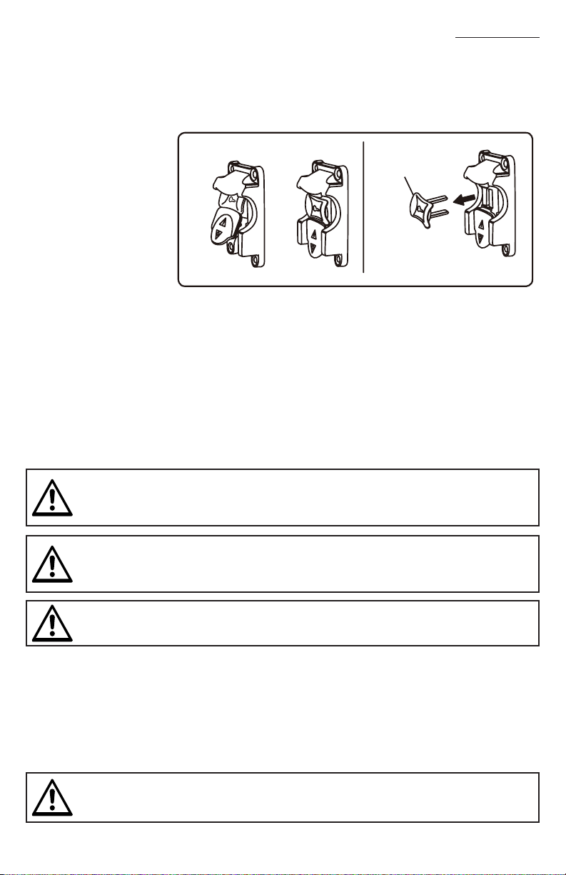
SWITCH ASSEMBLY
See Figure 3.
7KLVVDZLVHTXLSSHG
ZLWKDVZLWFKDVVHPEO\
WKDWKDVDEXLOWLQORFNLQJ
feature. This feature
LVLQWHQGHGWRSUHYHQW
XQDXWKRUL]HGDQG
SRVVLEOHKD]DUGRXVXVH
E\FKLOGUHQDQGRWKHUV
TO TURN YOUR
SAW ON:
:LWKWKHVZLWFKNH\LQVHUWHGLQWRWKHVZLWFKOLIWWKHVZLWFKWRWXUQRQO
TO TURN YOUR SAW OFF:
3UHVVWKHVZLWFKGRZQWRWXUQRII2
TO LOCK YOUR SAW:
• Press the switch down.
5HPRYHWKHVZLWFKNH\IURPWKHVZLWFKDQGVWRUHLQDVDIHVHFXUHORFDWLRQ
BLADES
)RUPD[LPXPSHUIRUPDQFHLWLVUHFRPPHQGHGWKDW\RXXVHWKHWRRWKFDUELGH
WLSSHGFRPELQDWLRQEODGHSURYLGHGZLWK\RXUVDZ$GGLWLRQDOEODGHVW\OHVRIWKHVDPHKLJK
TXDOLW\DUHDYDLODEOHIRUVSHFL¿FRSHUDWLRQVVXFKDVULSSLQJ
<RXUORFDOGHDOHUFDQSURYLGH\RXZ LWK FR PSOHWHLQIRUPDWLRQ.HUIZLGWKPXV WE HZ LWKLQWKH
OLPLWVVWDPSHGRQWKHULYLQJNQLIH
WARNING!
$/:$<6UHPRYHWKHVZLWFKNH\ZKHQWKHWRROLVQRWLQXVHDQGNHHSLWLQDVDIHSODFH,Q
WKHHYHQWRIDSRZHUIDLOXUHWXUQWKHVZLWFKRII2DQGUHPRYHWKHNH\7KLVDFWLRQZLOO
SUHYHQWWKHWRROIURPDFFLGHQWDOO\VWDUWLQJZKHQSRZHUUHWXUQV
WARNING!
$/:$<6PDNHVXUH\RXUZRUNSLHFHLVQRWLQFRQWDFWZLWKWKHEODGHEHIRUHRSHUDWLQJWKH
VZLWFKWRVWDUWWKHWRRO)DLOXUHWRKHHGWKLVZDUQLQJPD\FDXVHWKHZRUNSLHFHWREHNLFNHG
EDFNWRZDUGWKHRSHUDWRUDQGUHVXOWLQVHULRXVSHUVRQDOLQMXU\
WARNING!
7R UH GX FH W KH U LV N R I D F F L G H QW DO V WD UW LQ J $/:$< 6 PD NH V XU H WK H VZ LW FK L V LQ W KH R II 2
SRVLWLRQEHIRUHSOXJJLQJWRROLQWRWKHSRZHUVRXUFH
WARNING!
'RQRWXVHEODGHVUDWHGOHVVWKDQWKHVSHHGRIWKLVWRRO)DLOXUHWRKHHGWKLVZDUQLQJ
FRXOGUHVXOWLQSHUVRQDOLQMXU\
Fig. 3
SWITCH KEY
SWITCH IN LOCKED POSITION
SWITCH
OFF
SWITCH
ON
Here are the guidelines to help you understand the symbols used in this guide.
DANGER!
Indicates a potentially hazardous situation which could result in death or serious injury.
WARNING!
Indicates a situation which could result in death or serious injury
CAUTION!
Indicates a potentially hazardous situation which could result in mild to moderate injury
NOTICE:
When used without the Safety Alert symbol, this indicates a potentially hazardous
situation which, if not avoided, can result in property damage
TABLE OF CONTENTS
SAFETY GUIDELINES
Be sure to read and understand this manual for your safety. When using this product, it is
important to read and understand this information. It will protect you and help prevent any
problems
• KNOW YOUR POWER TOOL. Read the operator’s manual carefully. Learn the saw’s
tool.
• GUARD AGAINST ELECTRICAL SHOCK BY PREVENTING BODY CONTACT
WITH GROUNDED SURFACES. For example, pipes, radiators, ranges, refrigerator
enclosures.
• KEEP GUARDS IN PLACE and in good working order.
• REMOVE ADJUSTING KEYS AND WRENCHES. Form a habit of checking to see
that keys and adjusting wrenches are removed from tool before turning it on.
• KEEP WORK AREA CLEAN. Cluttered areas and benches invite accidents. DO NOT
leave tools or pieces of wood on the saw while it is in operation.
• DO NOT USE IN DANGEROUS ENVIRONMENTS. Do not use power tools in damp
or wet locations or expose to rain. Keep the work area well lit.
• KEEP CHILDREN AND VISITORS AWAY. All operators should wear safety glasses
and be kept a safe distance from work area. Do not contact tool or extension cord
while operating.
• MAKE WORKSHOP CHILDPROOF with padlocks and master switches, or by
removing starter keys.
2
SAFETY GUIDELINES ............................................2-7
FEATURES ......................................................8-9
ASSEMBLY & ADJUSTMENTS ..................................10-17
OPERATIONS ..................................................18-24
BLADE ADJUSTMENTS.........................................25-27
MAINTENANCE ................................................28-29
PARTS LIST ...................................................30-31
WARRANTY ......................................................32
C
H
B
E
A
F
D
G
JI
The following items are included with the table saw:
A. Anti-Kickback Pawls ................................................ 1
B. Blade Guard............................................................. 1
C. Push Stick ............................................................... 1
D. Handle...................................................................... 1
E. Miter Gauge ............................................................. 1
F. Rip Fence................................................................. 1
G. Locking Lever .......................................................... 1
H. Screws & Nut.s........................................................ 16
I. Closed End Wrench ................................................. 1
J. Closed End Wrench ................................................. 1
Fig. 5
ASSEMBLY AND ADJUSTMENTS
LOOSE PARTS
10
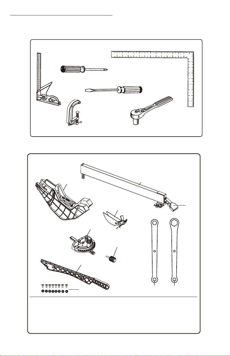
TOOLS NEEDED
The following tools (not included or drawn to scale) are needed for assembly and making adjustments:
Fig. 4
PHILLIPS
SCREWDRIVER
COMBINATION
SQUARE
FRAMING SQUARE
SOCKET WRENCH
WITH 10mmAND
1 1 m m S O C K E T
FLATHEAD
SCREWDRIVER
C-CLAMPS
UNPACKING
7KLVSURGXFWUHTXLUHVDVVHPEO\
&DUHIXOO\OLIWVDZIURPWKH
FDUWRQDQGSODFHLWRQDOHYHO
ZRUNVXUIDFH
NOTE:7KLVWRROLVKHDY\7R
DYRLGEDFNLQMXU\NHHS\RXU
NQHHVEHQWDQGOLIWZLWK\RXUOHJV
QRW\RXUEDFNDQGJHWKHOSZKHQ
needed.
,QVSHFWWKHWRROFDUHIXOO\WRPDNHVXUHQREUHDNDJHRUGDPDJHRFFXUUHGGXULQJ
VKLSSLQJ
'RQRWGLVFDUGWKHSDFNLQJPDWHULDOXQWLO\RXKDYHFDUHIXOO\LQVSHFWHGWKHWRRO
LQGHQWL¿HGDOOORRVHSDUWVDQGVDWLVIDFWRULO\RSHUDWHGWKHWRRO
NOTE:5HPRYHWKHIRDPEORFNIURPEHWZHHQWKHVDZVKRXVLQJDQGWKHPRWRUE\¿UVW
EHYHOLQJWKHEODGH
7KHVDZLVIDFWRU\VHWIRUDFFXUDWHFXWWLQJ$IWHUDVVHPEOLQJLWFKHFNIRUDFFXUDF\
,IVKLSSLQJKDVLQÀXHQFHGWKHVHWWLQJVUHIHUWRVSHFL¿FSURFHGXUHVH[SODLQHGLQWKLV
manual.
ASSEMBLY AND ADJUSTMENTS
Fig. 6
A
B
E
F
A
B
C
D
E
E
E
F
F
F
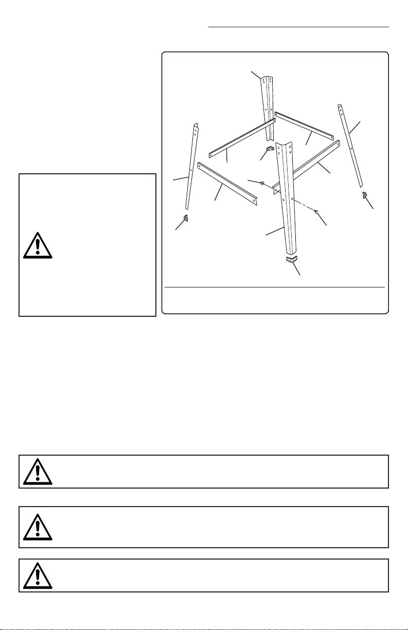
The following items are included with the table saw leg stand:
A. Lower Braces..............................................................2
B. Lower Side Braces......................................................2
C.
D.CarriageBolts........................................................... 8
E.Feet...........................................................................4
F.Legs............................................................................4
Hex Nuts.................................................................. 8
WARNING!
,IDQ\SDUWVDUHGDPDJHGRUPLVVLQJGRQRWRSHUDWHWKLVWRROXQWLOWKHSDUWVDUHUHSODFHG
8VHRIWKLVSURGXFWZLWKGDPDJHGRUPLVVLQJSDUWVFRXOGUHVXOWLQVHULRXVSHUVRQDOLQMXU\
WARNING!
'RQRWDWWHPSWWRPRGLI\WKLVWRRORUFUHDWHDFFHVVRULHVQRWUHFRPPHQGHGIRUXVHZLWK
WKLVWRRO$Q\VXFKDOWHUDWLRQRUPRGL¿FDWLRQLVPLVXVHDQGFRXOGUHVXOWLQDKD]DUGRXV
FRQGLWLRQOHDGLQJWRSRVVLEOHVHULRXVSHUVRQDOLQMXU\
WARNING!
'RQRWFRQQHFWWRSRZHUVXSSO\XQWLODVVHPEO\LVFRPSOHWH)DLOXUHWRFRPSO\FRXOGUHVXOW
LQDFFLGHQWDOVWDUWLQJDQGSRVVLEOHVHULRXVSHUVRQDOLQMXU\
WARNING!
'RQRWXVHWKLVSURGXFW
if any parts on the
Loose Parts Lists are
DOUHDG\DVVHPEOHGWR
your product when you
XQSDFNLW3DUWVRQWKLV
OLVWDUHQRWDVVHPEOHG
WRWKHSURGXFWE\WKH
PDQXIDFWXUHUDQGUHTXLUH
customer installation. Use
of a product that may
KDYHEHHQLPSURSHUO\
DVVHPEOHGFRXOGUHVXOWLQ
VHULRXVSHUVRQDOLQMXU\
11
LOOSE PARTS

Here are the guidelines to help you understand the symbols used in this guide.
DANGER!
Indicates a potentially hazardous situation which could result in death or serious injury.
WARNING!
Indicates a situation which could result in death or serious injury
CAUTION!
Indicates a potentially hazardous situation which could result in mild to moderate injury
NOTICE:
When used without the Safety Alert symbol, this indicates a potentially hazardous
situation which, if not avoided, can result in property damage
TABLE OF CONTENTS
SAFETY GUIDELINES
Be sure to read and understand this manual for your safety. When using this product, it is
important to read and understand this information. It will protect you and help prevent any
problems
• KNOW YOUR POWER TOOL. Read the operator’s manual carefully. Learn the saw’s
tool.
• GUARD AGAINST ELECTRICAL SHOCK BY PREVENTING BODY CONTACT
WITH GROUNDED SURFACES. For example, pipes, radiators, ranges, refrigerator
enclosures.
• KEEP GUARDS IN PLACE and in good working order.
• REMOVE ADJUSTING KEYS AND WRENCHES. Form a habit of checking to see
that keys and adjusting wrenches are removed from tool before turning it on.
• KEEP WORK AREA CLEAN. Cluttered areas and benches invite accidents. DO NOT
leave tools or pieces of wood on the saw while it is in operation.
• DO NOT USE IN DANGEROUS ENVIRONMENTS. Do not use power tools in damp
or wet locations or expose to rain. Keep the work area well lit.
• KEEP CHILDREN AND VISITORS AWAY. All operators should wear safety glasses
and be kept a safe distance from work area. Do not contact tool or extension cord
while operating.
• MAKE WORKSHOP CHILDPROOF with padlocks and master switches, or by
removing starter keys.
2
SAFETY GUIDELINES ............................................2-7
FEATURES ......................................................8-9
ASSEMBLY & ADJUSTMENTS ..................................10-17
OPERATIONS ..................................................18-24
BLADE ADJUSTMENTS.........................................25-27
MAINTENANCE ................................................28-29
PARTS LIST ...................................................30-31
WARRANTY ......................................................32
MOUNTING THE TABLE SAW BASE ON
THE LEG STAND
• Take the following from the table saw
base: 8 hex bolts
NOTE
• Place the table saw base on the leg
stand. Align the holes in the table.
• Place a bolt in each hole. Hand tighten.
• Repeat for three remaining holes.
Tighten all hardware securely with the
socket wrench.
ASSEMBLY AND ADJUSTMENTS
12
WARNING!
Never stand directly in line with the blade or allow hands to come closer than 3 in. to the
blade. Do not reach over or across the blade. Failure to heed this warning can result in
serious personal injury.
WARNING!
To avoid serious personal injury, always make sure the table saw is securely mounted to
.
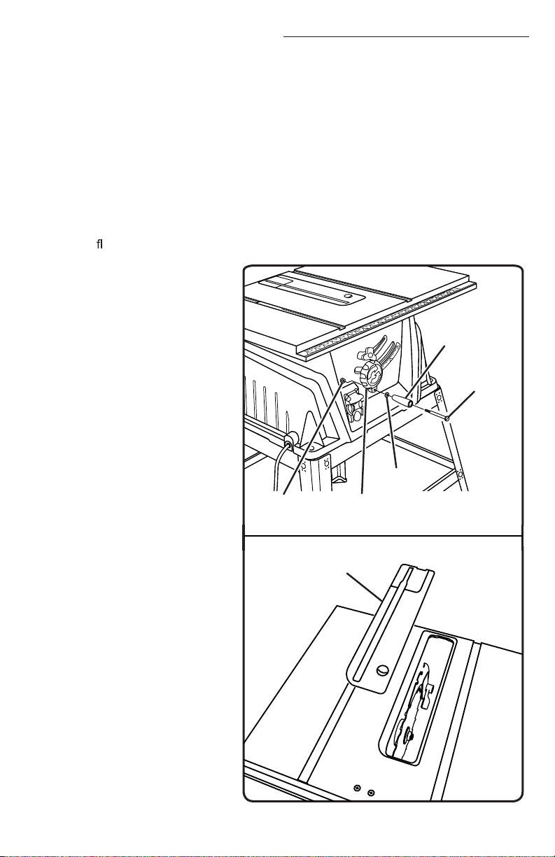
TO INSTALL THE HANDLE
See Figure 9.
• Hold the nylon nut securely and turn the screw counterclockwise to remove the nut
completely.
NOTE: Do not remove the screw from the handle.
• Place the nylon nut into the recessed hole on the back of the height/bevel adjusting
handwheel and hold in place.
• Slide the handle, screw, and washer into the hole on the height/bevel adjusting
handwheel.
• Usingaathead screwdriver, turn the screw clockwise and tighten in place.
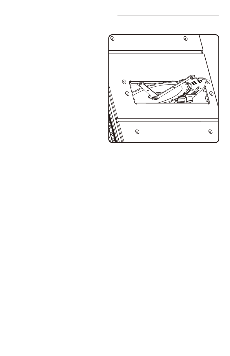
TO REMOVE/REPLACE THE
TABLE INSERT
See Figure 10.
• Lower the blade by turning
the height/bevel adjusting
handwheel counterclockwise.
• Remove the table insert.
ASSEMBLY AND ADJUSTMENTS
HEIGHT/BEVEL
ADJUSTING HANDWHEEL Fig. 9
SCREW
NYLON
NUT
WA S H E R
HANDLE
TABLE
INSERT
Fig. 10
13
Here are the guidelines to help you understand the symbols used in this guide.
DANGER!
Indicates a potentially hazardous situation which could result in death or serious injury.
WARNING!
Indicates a situation which could result in death or serious injury
CAUTION!
Indicates a potentially hazardous situation which could result in mild to moderate injury
NOTICE:
When used without the Safety Alert symbol, this indicates a potentially hazardous
situation which, if not avoided, can result in property damage
TABLE OF CONTENTS
SAFETY GUIDELINES
Be sure to read and understand this manual for your safety. When using this product, it is
important to read and understand this information. It will protect you and help prevent any
problems
• KNOW YOUR POWER TOOL. Read the operator’s manual carefully. Learn the saw’s
tool.
• GUARD AGAINST ELECTRICAL SHOCK BY PREVENTING BODY CONTACT
WITH GROUNDED SURFACES. For example, pipes, radiators, ranges, refrigerator
enclosures.
• KEEP GUARDS IN PLACE and in good working order.
• REMOVE ADJUSTING KEYS AND WRENCHES. Form a habit of checking to see
that keys and adjusting wrenches are removed from tool before turning it on.
• KEEP WORK AREA CLEAN. Cluttered areas and benches invite accidents. DO NOT
leave tools or pieces of wood on the saw while it is in operation.
• DO NOT USE IN DANGEROUS ENVIRONMENTS. Do not use power tools in damp
or wet locations or expose to rain. Keep the work area well lit.
• KEEP CHILDREN AND VISITORS AWAY. All operators should wear safety glasses
and be kept a safe distance from work area. Do not contact tool or extension cord
while operating.
• MAKE WORKSHOP CHILDPROOF with padlocks and master switches, or by
removing starter keys.
2
SAFETY GUIDELINES ............................................2-7
FEATURES ......................................................8-9
ASSEMBLY & ADJUSTMENTS ..................................10-17
OPERATIONS ..................................................18-24
BLADE ADJUSTMENTS.........................................25-27
MAINTENANCE ................................................28-29
PARTS LIST ...................................................30-31
WARRANTY ......................................................32
TO CHANGE RIVING KNIFE POSITIONS
6HH)LJXUH
7KLVVDZLVVKLSSHGZLWKDULYLQJNQLIHWKDW
VKRXOGEHSODFHGLQWKH³GRZQ´SRVLWLRQIRU
QRQWKURXJKFXWWLQJDQGPXVWEHSODFHG
LQWKH³XS´SRVLWLRQIRUDOORWKHUFXWWLQJ
operations.
8QSOXJWKHVDZ
To place in the “up” position for all
through cutting:
5HPRYHWKHWDEOHLQVHUW
5DLVHWKHVDZEODGHE\WXUQLQJWKH
KHLJKWEHYHODGMXVWLQJKDQGZKHHO
FORFNZLVH
8QORFNWKHUHOHDVHOHYHUE\SXOOLQJLW
up.
*UDVSWKHULYLQJNQLIHDQGSXOOLW
WRZDUGVWKHULJKWVLGHRIWKHVDZ
WRUHOHDVHWKHULYLQJNQLIHIURPWKH
VSULQJORDGHGULYLQJFODPS
3XOOWKHULYLQJNQLIHXSXQWLOWKH
LQWHUQDOSLQVDUHHQJDJHGDQGWKH
ULYLQJNQLIHLVDERYHWKHVDZEODGH
/RFNWKHUHOHDVHOHYHUE\SXVKLQJWKH
OHYHUGRZQ
5HLQVWDOOWKHWDEOHLQVHUW
To place in riving knife “down” position for all nonthrough cutting:
5HPRYHWKHWDEOHLQVHUW
5DLVHWKHVDZEODGHE\WXUQLQJWKHKHLJKWEHYHODGMXVWLQJKDQGZKHHOFORFNZLVH
8QORFNWKHUHOHDVHOHYHUE\SXOOLQJLWXS
*UDVSWKHULYLQJNQLIHDQGSXOOLWWRZDUGVWKHULJKWVLGHRIWKHVDZWRUHOHDVHWKHULYLQJ
NQLIHIURPWKHVSULQJORDGHGULYLQJFODPS
3XVKWKHULYLQJNQLIHGRZQXQWLOLWLVEHORZWKHVDZEODGH
3XOOWKHULYLQJNQLIHXSXQWLOWKHLQWHUQDOSLQVDUHHQJDJHGDQGWKHULYLQJNQLIHLVDERYH
WKHVDZEODGH
/RFNWKHUHOHDVHOHYHUE\SXVKLQJWKHOHYHUGRZQ
5HLQVWDOOWKHWDEOHLQVHUW
ASSEMBLY AND ADJUSTMENTS
IN “UP” POSITION FOR THROUGH CUTTING
IN “DOWN” POSITION FOR
NON-THROUGH CUTTING
RELEASE LEVER
(LOCKED)
Fig. 11
RELEASE LEVER
(UNLOCKED)
14
TO CHECK SAW BLADE INSTALLATION
6HH)LJXUH
NOTICE:7RZRUNSURSHUO\WKHVDZ
EODGHWHHWKPXVWSRLQWGRZQWRZDUGWKH
IURQWRIWKHVDZ)DLOXUHWRGRVRFRXOG
FDXVHGDPDJHWRWKHVDZEODGHWKH
VDZRUWKHZRUNSLHFH
8QSOXJWKHVDZ
/RZHUWKHVDZEODGHDQGUHPRYH
WKHWDEOHLQVHUW
0DNHVXUHWKHEHYHOORFNLQJOHYHU
LVVHFXUHO\SXVKHGWRWKHULJKW
5DLVHWKHVDZEODGHWRLWVIXOO
KHLJKWE\WXUQLQJWKHKHLJKWEHYHO
DGMXVWLQJKDQGZKHHOFORFNZLVH
3ODFHULYLQJNQLIHLQ³XS´SRVLWLRQ
To loosen the blade:
,QVHUWWKHFORVHGHQGZUHQFKRQWKHEODGHZDVKHU
,QVHUWWKHFORVHGHQGEODGHZUHQFKRYHUWKHEODGHQXW+ROGLQJERWKZUHQFKHV¿UPO\
pull the closed end wrench forward to the front of the machine.
To tighten the blade:
,QVHUWWKHFORVHGHQGZUHQFKRQWKHEODGHZDVKHU
,QVHUWWKHFORVHGHQGEODGHZUHQFKRYHUWKHEODGHQXW+ROGLQJERWKZUHQFKHV¿UPO\
SXVKWKHFORVHGHQGZUHQFKWRWKHEDFNRIWKHPDFKLQH0DNHVXUHWKHEODGHQXWLV
VHFXUHO\WLJKWHQHG'RQRWRYHUWLJKWHQ
5HLQVWDOOWKHWDEOHLQVHUW
&KHFNDOOFOHDUDQFHVIRUIUHHEODGHURWDWLRQ
ASSEMBLY AND ADJUSTMENTS
Fig. 12
15
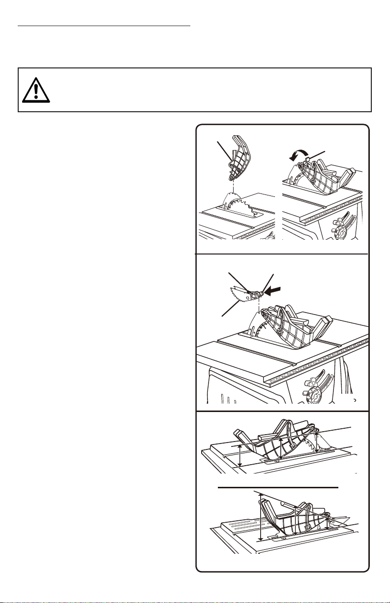
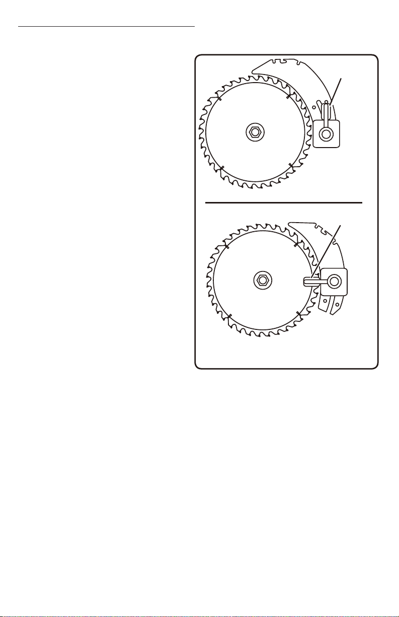
TO INSTALL THE BLADE GUARD AND ANTI-KICKBACK PAWLS
6HH)LJXUHV
8QSOXJWKHVDZ
5DLVHWKHVDZEODGHE\WXUQLQJWKH
KHLJKWEHYHODGMXVWLQJKDQGZKHHO
FORFNZLVH
3ODFHULYLQJNQLIHLQ³XS´SRVLWLRQ
5HLQVWDOOWKHWDEOHLQVHUW
To install anti-kickback pawls:
3UHVVDQGKROGWKHEXWWRQRQWKHULJKW
VLGHRIWKHDQWLNLFNEDFNSDZOV
$OLJQWKHVORWLQWKHSDZOVRYHUWKHUHDU
KROHLQWKHULYLQJNQLIH
3XVKWKHSDZOKDQGOHGRZQVQDSSLQJ
WKHPLQWRSODFHDQGUHOHDVHWKHEXWWRQ
NOTE:3XOORQWKHSDZOKDQGOHWRPDNH
VXUHSDZOVDUHVHFXUHO\ORFNHG
TO INSTALL THE BLADE GUARD:
/LIWWKHJXDUGOHYHUXSWRXQORFN
:LWKWKHIURQWRIWKHEODGHJXDUG
UDLVHGORZHUWKHEDFNRIWKHJXDUG
LQWRWKHPLGGOHKROHRIWKHULYLQJNQLIH
3XVKWKHIURQWRIWKHJXDUGGRZQXQWLO
LWLVSDUDOOHOWRWKHWDEOHVHH¿JXUH
,IWKHEODGHJXDUGLVQRWSDUDOOHOWRWKH
WDEOHWKHULYLQJNQLIHLVQRWLQWKH³XS´
position.
/RFNWKHJXDUGLQSODFHE\SXVKLQJWKH
JXDUGOHYHUGRZQ
NOTE:%ODGHDOLJQPHQWFDQEHDGMXVWHG
IRUGLIIHUHQWEODGHZLGWKV5HIHUWR7R
&KHFNDQG$OLJQWKH5LYLQJ.QLIHDQG6DZ
%ODGH&KHFNWKHEODGHJXDUGDVVHPEO\IRU
FOHDUDQFHVDQGIUHHPRYHPHQW
WARNING!
5HSODFHGXOORUGDPDJHGDQWLNLFNEDFNSDZOV'XOORUGDPDJHGSDZOVPD\QRWVWRSD
NLFNEDFNLQFUHDVLQJWKHULVNRIVHULRXVSHUVRQDOLQMXU\
$QWLNLFNEDFNSDZOVVKRXOGRQO\EHLQVWDOOHGIRUWKURXJKFXWV
ASSEMBLY AND ADJUSTMENTS
ANTI-KICKBACK
PAW L S
PAW L
HANDLE BUTTON
Fig. 14
Fig. 13
BLADE
GUARD
GUARD
LEVER
Fig. 15
CORRECT
INCORRECT
16

TO CHECK AND ALIGN THE RIVING KNIFE AND
SAW BLADE
6HH)LJXUHV
To check alignment of the riving knife:
8QSOXJWKHVDZ
5DLVHWKHVDZEODGHE\WXUQLQJWKHKHLJKWEHYHO
DGMXVWLQJKDQGZKHHOFORFNZLVH
5HPRYHWKHDQWLNLFNEDFNSDZOVDQGEODGH
JXDUGDVVHPEO\3ODFHDIUDPLQJVTXDUHRU
VWUDLJKWHGJHDJDLQVWERWKWKHVDZEODGHDQGWKH
ULYLQJNQLIH
NOTE:3ODFHIUDPLQJVTXDUHEHWZHHQFDUELGH
WHHWKDQGPHDVXUHIURPEODGH7KLVVWHSZLOOLQVXUH
IUDPLQJVTXDUHLVVTXDUHDJDLQVWEODGHIURPWKHIURQW
WREDFNRIEODGH
7KHVDZEODGHDQGULYLQJNQLIHDUHDOLJQHGZKHQ
WKHIUDPLQJVTXDUHFRQWDFWVERWKWKHEODGHDQG
ULYLQJNQLIHHYHQO\ZLWKQRJDSV,IWKHULYLQJ
NQLIHLVRXWRIDOLJQPHQWZLWKWKHVDZEODGH
DGMXVWPHQWLVQHHGHG7KHULYLQJNQLIHPXVWEH
LQDOLJQPHQWIURQWWREDFNKRUL]RQWDOO\DQGWRS
WRERWWRPYHUWLFDOO\
To adjust (horizontally and vertically):
5HPRYHWKHDQWLNLFNEDFNSDZOVDQGEODGH
JXDUGDVVHPEO\
*UDVSWKHRXWIHHGVXSSRUWZLWKERWKKDQGVDQG
SXOOLWXQWLOLWLVIXOO\H[WHQGHG
)URPWKHEDFNRIWKHVDZORRVHQWKHVFUHZV
KROGLQJWKHPRXQWLQJEUDFNHW
5HSRVLWLRQWKHULYLQJNQLIHOHIWRUULJKWDVQHHGHGWR
DOLJQWKHULYLQJNQLIHZLWKWKHVDZEODGH
2QFHSURSHUO\DOLJQHGVHFXUHO\UHWLJKWHQDOO
screws.
&KHFNDJDLQIRUVTXDUHQHVVDQGFRQWLQXHWRDGMXVW
if needed.
ASSEMBLY AND ADJUSTMENTS
Fig. 17
FRAMING
SQUARE
Fig. 16
RIVING
KNIFE
FRAMING
SQUARE
FRAMING
SQUARE
RIVING
KNIFE
BLADE
BLADE
RIVING
KNIFE
HORIZONTAL ADJUSTMENT
VERTICAL ADJUSTMENT
17
WRENCH AND BLADE STORAGE
6HH)LJXUH
Insert Blade and wrench into the holes on the side of
WKHWDEOHVDZWLJKWHQVFUHZVVHFXUHO\7KHSXVKVWLFN
DQGSRZHUFDEOHKDYHRQERDUGVWRUDJHDVVKRZQLQ
)LJ
Fig. 18

TO CHANGE RIVING KNIFE POSITIONS
6HH)LJXUH
7KLVVDZLVVKLSSHGZLWKDULYLQJNQLIHWKDW
VKRXOGEHSODFHGLQWKH³GRZQ´SRVLWLRQIRU
QRQWKURXJKFXWWLQJDQGPXVWEHSODFHG
LQWKH³XS´SRVLWLRQIRUDOORWKHUFXWWLQJ
operations.
8QSOXJWKHVDZ
To place in the “up” position for all
through cutting:
5HPRYHWKHWDEOHLQVHUW
5DLVHWKHVDZEODGHE\WXUQLQJWKH
KHLJKWEHYHODGMXVWLQJKDQGZKHHO
FORFNZLVH
8QORFNWKHUHOHDVHOHYHUE\SXOOLQJLW
up.
*UDVSWKHULYLQJNQLIHDQGSXOOLW
WRZDUGVWKHULJKWVLGHRIWKHVDZ
WRUHOHDVHWKHULYLQJNQLIHIURPWKH
VSULQJORDGHGULYLQJFODPS
3XOOWKHULYLQJNQLIHXSXQWLOWKH
LQWHUQDOSLQVDUHHQJDJHGDQGWKH
ULYLQJNQLIHLVDERYHWKHVDZEODGH
/RFNWKHUHOHDVHOHYHUE\SXVKLQJWKH
OHYHUGRZQ
5HLQVWDOOWKHWDEOHLQVHUW
To place in riving knife “down” position for all nonthrough cutting:
5HPRYHWKHWDEOHLQVHUW
5DLVHWKHVDZEODGHE\WXUQLQJWKHKHLJKWEHYHODGMXVWLQJKDQGZKHHOFORFNZLVH
8QORFNWKHUHOHDVHOHYHUE\SXOOLQJLWXS
*UDVSWKHULYLQJNQLIHDQGSXOOLWWRZDUGVWKHULJKWVLGHRIWKHVDZWRUHOHDVHWKHULYLQJ
NQLIHIURPWKHVSULQJORDGHGULYLQJFODPS
3XVKWKHULYLQJNQLIHGRZQXQWLOLWLVEHORZWKHVDZEODGH
3XOOWKHULYLQJNQLIHXSXQWLOWKHLQWHUQDOSLQVDUHHQJDJHGDQGWKHULYLQJNQLIHLVDERYH
WKHVDZEODGH
/RFNWKHUHOHDVHOHYHUE\SXVKLQJWKHOHYHUGRZQ
5HLQVWDOOWKHWDEOHLQVHUW
ASSEMBLY AND ADJUSTMENTS
IN “UP” POSITION FOR THROUGH CUTTING
IN “DOWN” POSITION FOR
NON-THROUGH CUTTING
RELEASE LEVER
(LOCKED)
Fig. 11
RELEASE LEVER
(UNLOCKED)
14
APPLICATIONS
<RXPD\XVHWKLVWRROIRUWKH SX USR VHVOLVWHGEHORZ
6WUDLJKWOLQHFXWWLQJRSHUDWLRQVVXFKDVFURVVFXWWLQJULSSLQJPLWHULQJEHYHOLQJDQG
FRPSRXQGFXWWLQJ
&DELQHWPDNLQJDQGZRRGZRUNLQJ
NOTE:7KLVWDEOHVDZLVGHVLJQHGWRFXWZRRGDQGZRRGFRPSRVLWLRQSURGXFWVRQO\
BASIC OPERATION OF THE TABLE SAW
7KHSRODUL]HGSOXJPXVWEHSOXJJHGLQWRDPDWFKLQJRXWOHWWKDWLVSURSHUO\LQVWDOOHG
DQGJURXQGHGDFFRUGLQJWRDOOORFDOFRGHVDQGRUGLQDQFHV,PSURSHUFRQQHFWLRQRIWKH
HTXLSPHQWFDQUHVXOWLQHOHFWULFVKRFN'RQRWPRGLI\WKHSOXJLILWZLOOQRW¿WWKHRXWOHW
+DYHWKHFRUUHFWRXWOHWLQVWDOOHGE\DTXDOL¿HGHOHFWULFLDQ5HIHUWRWKH(OHFWULFDOVHFWLRQLQ
this manual.
CAUSES OF KICKBACK
.LFNEDFNFDQRFFXUZKHQWKHEODGHVWDOOVRUELQGVNLFNLQJWKHZRUNSLHFHEDFNWRZDUG
\RXZLWKJUHDWIRUFHDQGVSHHG,I\RXUKDQGVDUHQHDUWKHVDZEODGHWKH\PD\EHMHUNHG
ORRVHIURPWKHZRUNSLHFHDQGPD\FRQWDFWWKHEODGH.LFNEDFNFDQFDXVHVHULRXVLQMXU\
8VHSUHFDXWLRQVWRDYRLGWKHULVNV
.LFNEDFNFDQEHFDXVHGE\DQ\DFWLRQWKDWSLQFKHVWKHEODGHLQWKHZRRGVXFKDV
0DNLQJDFXWZLWKLQFRUUHFWEODGHGHSWK
6DZLQJLQWRNQRWVRUQDLOVLQWKHZRUNSLHFH
7ZLVWLQJWKHZRRGZKLOHPDNLQJDFXW
)DLOLQJWRVXSSRUWZRUN
)RUFLQJDFXW
&XWWLQJZDUSHGRUZHWOXPEHU
8VLQJWKHZURQJEODGHIRUWKHW\SHRIFXW
OPERATIONS
WARNING!
'RQRWDOORZIDPLOLDULW\ZLWKWRROVWRPDNH\RXFDUHOHVV5HPHPEHUWKDWDFDUHOHVV
IUDFWLRQRIDVHFRQGLVVXI¿FLHQWWRLQÀLFWVHYHUHLQMXU\
WARNING!
$OZD\VZHDUH\HSURWHFWLRQZLWKVLGHVKLHOGVPDUNHGWRFRPSO\ZLWK$16,=)DLOXUH
WRGRVRFRXOGUHVXOWLQREMHFWVEHLQJWKURZQLQWR\RXUH\HVUHVXOWLQJLQSRVVLEOHVHULRXV
LQMXU\
WARNING!
'RQRWXVHDQ\DWWDFKPHQWVRUDFFHVVRULHVQRWUHFRPPHQGHGE\WKHPDQXIDFWXUHURI
this tool. The use of attachments or accessories not recommended can result in serious
SHUVRQDOLQMXU\
WARNING!
$OWKRXJKPDQ\RIWKHLOOXVWUDWLRQVLQWKLVPDQXDODUHVKRZQZLWKWKHEODGHJXDUGUHPRYHG
IRUFODULW\GRQRWRSHUDWHWKHVDZZLWKRXWWKHEODGHJXDUGXQOHVVVSHFL¿FDOO\LQVWUXFWHGWR
do so.

1RWIROORZLQJFRUUHFWRSHUDWLQJSURFHGXUHV
0LVXVLQJWKHVDZ
)DLOLQJWRXVHWKHDQWLNLFNEDFNSDZOV
&XWWLQJZLWKDGXOOJXPPHGXSRULPSURSHUO\VHWEODGH
AVOIDING KICKBACK
$OZD\VXVHWKHFRUUHFWEODGHGHSWKVHWWLQJ7KHWRSRIWKHEODGHWHHWKVKRXOGFOHDU
WKHZRUNSLHFHE\LQWRLQ
,QVSHFWWKHZRUNIRUNQRWVRUQDLOVEHIRUHEHJLQQLQJDFXW.QRFNRXWDQ\ORRVHNQRWV
ZLWKDKDPPHU1HYHUVDZLQWRDORRVHNQRWRUQDLO
$OZD\VXVHWKHULSIHQFHZKHQULSFXWWLQJ8VHWKHPLWHUJDXJHZKHQFURVVFXWWLQJ
7KLVKHOSVSUHYHQWWZLVWLQJWKHZRRGLQWKHFXW
$OZD\VXVHFOHDQVKDUSDQGSURSHUO\VHWEODGHV1HYHUPDNHFXWVZLWKGXOOEODGHV
7RDYRLGSLQFKLQJWKHEODGHVXSSRUWWKHZRUNSURSHUO\EHIRUHEHJLQQLQJDFXW
:KHQPDNLQJDFXWXVHVWHDG\HYHQSUHVVXUH1HYHUIRUFHFXWV
'RQRWFXWZHWRUZDUSHGOXPEHU
8VHH[WUDFDXWLRQZKHQFXWWLQJVRPHSUH¿QLVKHGRUFRPSRVLWLRQZRRGSURGXFWVDV
WKHDQWLNLFNEDFNSDZOVPD\QRWDOZD\VEHHIIHFWLYH
$OZD\VJXLGH\RXUZRUNSLHFHZLWKERWKKDQGVRUZLWKSXVKVWLFNVDQGRUSXVKEORFNV
.HHS\RXUERG\LQDEDODQFHGSRVLWLRQWREHUHDG\WRUHVLVWNLFNEDFNVKRXOGLWRFFXU
1HYHUVWDQGGLUHFWO\LQOLQHZLWKWKHEODGH
8VHRIDIHDWKHUERDUGZLOOKHOSKROGWKHZRUNSLHFHVHFXUHO\DJDLQVWWKHVDZWDEOHRU
fence.
&OHDQWKHVDZEODGHJXDUGXQGHUWKHWDEOHLQVHUWDQGDQ\DUHDVZKHUHVDZGXVWRU
VFUDSZRUNSLHFHVPD\JDWKHU
8VHWKHULJKWW\SHRIEODGHIRUWKHFXWEHLQJPDGH
$OZD\VXVHWKHULYLQJNQLIHIRUHYHU\RSHUDWLRQZKHUHLWLVDOORZHG7KHXVHRIWKLV
GHYLFHZLOOJUHDWO\UHGXFHWKHULVNRINLFNEDFN
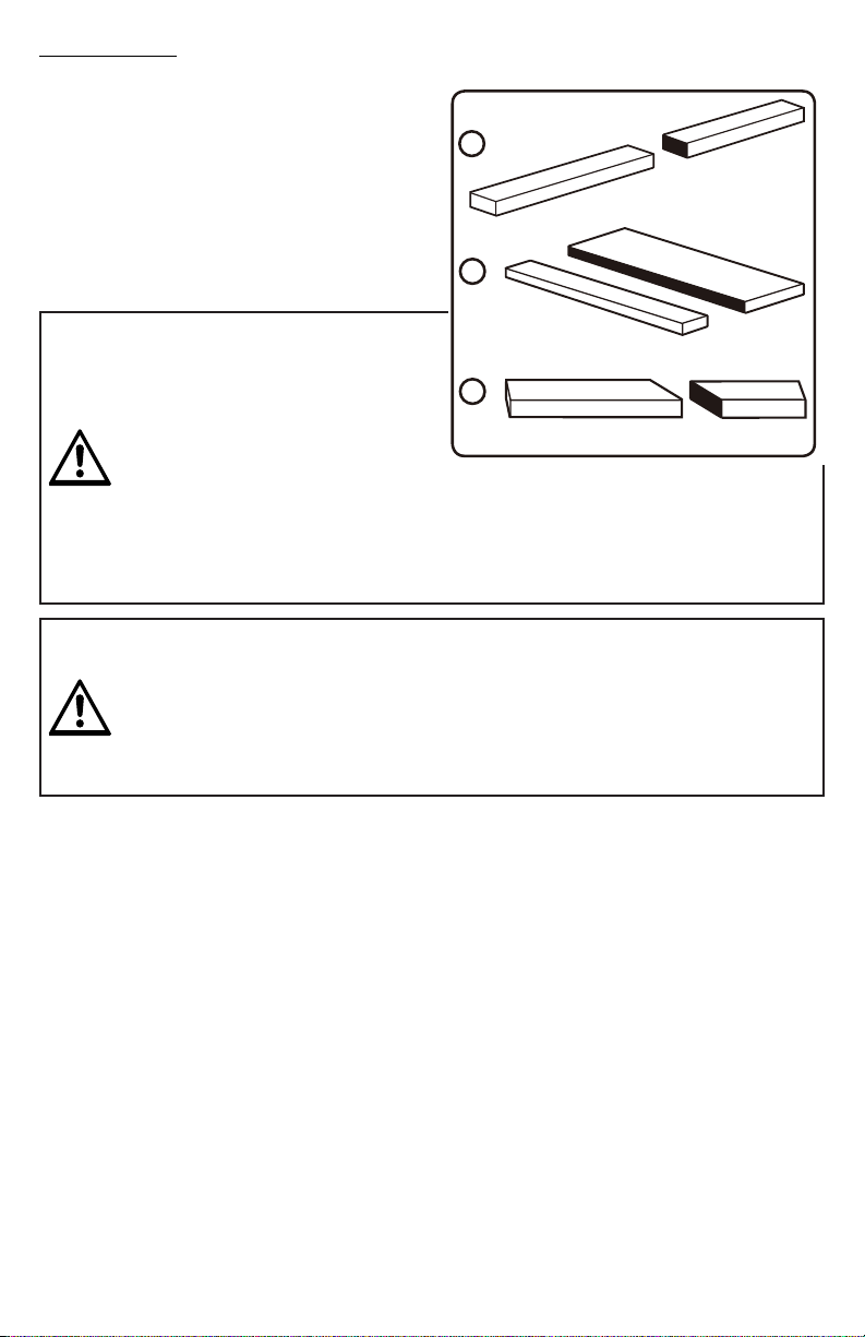
CUTTING AIDS
6HH)LJXUH
3XVKVWLFNVDUHGHYLFHVWKDWPD\EHXVHGIRUSXVKLQJDZRUNSLHFHWKURXJKWKHEODGHLQ
DQ\ULSFXW:KHQPDNLQJQRQWKURXJKFXWVRUULSSLQJQDUURZVWRFNDOZD\VXVHDSXVK
VWLFNSXVKEORFNDQGRUIHDWKHUERDUGVR\RXUKDQGVGRQRWFRPHZLWKLQLQFKHVRIWKH
VDZEODGH7KH\FDQEHPDGHLQYDULRXVVL]HVDQGVKDSHVIURPVFUDSZRRGDQGXVHGLQ
DVSHFL¿FSURMHFW7KHVWLFNPXVWEHQDUURZHUWKDQWKHZRUNSLHFHZLWKDÛQRWFKLQRQH
HQGDQGVKDSLQJIRUDJULSRQWKHRWKHUHQG
$SXVKEORFNKDVDKDQGOHIDVWHQHGE\UHFHVVHGVFUHZVIURPWKHXQGHUVLGH8VHSXVK
EORFNVIRUQDUURZFXWVDQGDOOQRQWKURXJKFXWV
NOTICE:%HVXUHWKHVFUHZVLQDSXVKEORFNDUHUHFHVVHGWRDYRLGGDPDJLQJWKHVDZRU
ZRUNSLHFH
OPERATIONS
TYPE OF CUTS
6HH)LJXUH
7KHUHDUHVL[EDVLFFXWVWKHFURVVFXW
WKHULSFXWWKHPLWHUFXWWKHEHYHO
FURVVFXWWKHEHYHOULSFXWDQGWKH
FRPSRXQGEHYHOPLWHUFXW$OORWKHUFXWVDUH
FRPELQDWLRQVRIWKHVHEDVLFVL[2SHUDWLQJ
SURFHGXUHVIRUPDNLQJHDFKNLQGRIFXWDUH
JLYHQODWHULQWKLVVHFWLRQ
L
K
WARNING!
$OZD\VPDNHVXUHWKHEODGHJXDUGDQG
DQWLNLFNEDFNSDZOVDUHLQSODFHDQG
ZRUNLQJSURSHUO\ZKHQPDNLQJWKHVH
FXWVWRDYRLGSRVVLEOHLQMXU\
&URVVFXWVDUHVWUDLJKWFXWVPDGH
DFURVVWKHJUDLQRIWKHZRUNSLHFH7KH
ZRRGLVIHGLQWRWKHFXWDWDDQJOHWR
WKHEODGHDQGWKHEODGHLVYHUWLFDO
5LSFXWVDUHPDGHZLWKWKHJUDLQRIWKHZRRG7RDYRLGNLFNEDFNZKLOHPDNLQJDULSFXW
PDNHVXUHRQHVLGHRIWKHZRRGULGHV¿UPO\DJDLQVWWKHULSIHQFH
0LWHUFXWVDUHPDGHZLWKWKHZRRGDWDQ\DQJOHWRWKHEODGHRWKHUWKDQ7KHEODGH
LVYHUWLFDO0LWHUFXWVWHQGWR³FUHHS´GXULQJFXWWLQJ7KLVFDQEHFRQWUROOHGE\KROGLQJWKH
ZRUNSLHFHVHFXUHO\DJDLQVWWKHPLWHUJDXJH
WARNING!
$OZD\VXVHDSXVKVWLFNZLWKVPDOOSLHFHVRIZRRGDQGDOVRWR¿QLVKWKHFXWZKHQULSSLQJ
DORQJQDUURZSLHFHRIZRRGWRSUHYHQW\RXUKDQGVIURPJHWWLQJFORVHWRWKHEODGH
%HYHOFXWVDUHPDGHZLWKDQDQJOHGEODGH%HYHOFURVVFXWVDUHDFURVVWKHZRRGJUDLQ
DQGEHYHOULSFXWVDUHZLWKWKHJUDLQ
&RPSRXQGRUEHYHOPLWHUFXWVDUHPDGHZLWKDQDQJOHGEODGHRQZRRGWKDWLVDQJOHG
WRWKHEODGH%HWKRURXJKO\IDPLOLDUZLWKPDNLQJFURVVFXWVULSFXWVEHYHOFXWVDQGPLWHU
FXWVEHIRUHWU\LQJDFRPSRXQGPLWHUFXW
RIP CUT
CROSS CUT
MITER CUT
1
2
3
Fig. 24
OPERATIONS
20
This manual suits for next models
1
Other CH Hanson Saw manuals


