CH Hanson PALMGREEN 9683336 Instructions for use

Operating Instructions & Parts Manual EN
9” Cold Saw
230 V, 1-Phase
Model 9683336
9644292.01

PLEASE READ AND SAVE
THESE INSTRUCTIONS.
READ CAREFULLY
BEFORE ATTEMPTING
TO ASSEMBLE, INSTALL,
OPERATE OR MAINTAIN THE
PRODUCT DESCRIBED.
PROTECT YOURSELF AND
OTHERS BY OBSERVING ALL
SAFETY INFORMATION. FAILURE
TO COMPLY WITH INSTRUCTIONS
COULD RESULT IN PERSONAL
INJURY AND/OR PROPERTY
DAMAGE! RETAIN INSTRUCTIONS
FOR FUTURE REFERENCE.
PLEASE REFER TO BACK COVER
FOR INFORMATION REGARDING
PALMGREN’S WARRANTY
AND OTHER IMPORTANT
INFORMATION.
Model #: ___________________
Serial #: ___________________
Purch. Date: _______________
© 2019 Palmgren / a C.H. Hanson Brand
All Rights Reserved
3
GETTING STARTED SAFETY / SPECIFICATIONS ASSEMBLY / INSTALLATION OPERATION TROUBLESHOOTING MAINTENANCE / REPAIR
GETTING STARTED
Save this manual
You will need this manual for the safety warnings and
precautions, assembly instructions, operating and maintenance
procedures, parts lists and diagrams. Keep your invoice with this
manual. Write the invoice number on the inside of the front cover.
Keep this manual and invoice in a safe and dry place for future
reference.
Structural requirements
Make sure all supporting structures and load attaching
devices are strong enough to hold your intended loads.
If in doubt, consult a qualified structural engineer.
Electrical requirements
This saw does not come with a plug, and can be wired
to a plug or directly into the power main. Blue wire is
neutral, brown is line wire, and yellow with a green
stripe is ground.
The circuit must be configured to provide 230VAC at 5.5A, single-
phase, 60 Hz.
Tools needed
Standard professional mechanic’s hand tool set.
UNPACKING
Be careful not to touch overhead power
lines, piping, lighting, etc. if lifting
equipment is used. Cold Saw weighs approximately 90 lbs
(41 kg), proper tools, equipment and qualified personnel
should be employed in all phases of unpacking and
installation.
Carton should be handled with care to avoid damage from
dropping, bumping, etc. Store and unpack carton with correct
side up. Unpack all parts from the container. Check for damage
as each piece is removed. Especially check the tubing located
at the bottom of the motor for kinks, cuts, or other damage that
would be detrimental to coolant flow. After unpacking Saw,
inspect carefully for any damage that may have occurred during
transit. Check for loose, missing or damaged parts. If any
damage or loss has occurred, claim must be filed with carrier
immediately. Check for completeness. Immediately report
missing parts to dealer.
Never use highly volatile solvents. Non
flammable solvents are recommended to
avoid possible fire hazard. Avoid getting cleaning solution
on paint as it may tend to deteriorate these finishes. Use
soap and water on painted components.
Dayton model 9683336 9” Cold Saw is shipped complete in one
box. The saw comes assembled as one unit. Additional parts
which need to be assembled or fastened to the saw should be
located and accounted for before assembling.
IMPORTANT: Many unpainted steel surfaces have been
coated with a protectant. To ensure proper fit and operation,
remove the coating. Coating can be easily removed with mild
solvents, such as mineral spirits, and a soft cloth. Avoid getting
solution on paint or any of the rubber/plastic parts. Solvents may
deteriorate these finishes. Use soap and water on paint, plastic
or rubber components. After cleaning, cover all exposed surfaces
with a light coating of oil.
Package Contents:
Saw unit 1
Trigger handle 1
Trigger handle rod 1
Depth stop rods 1
Allen wrench set,
sizes: 3, 4, 5, 6, 14
1 ea
Manual 1
Unpack
After unpacking the unit, carefully inspect for any
damage that may have occurred during transit. Check
for loose, missing or damaged parts. Shipping damage claims
must be filed with the carrier.
Inspect
After unpacking the unit, carefully inspect for any
damage that may have occurred during transit. Check
for loose, missing or damaged parts. Shipping damage
claims must be filed with the carrier.
All tools should be visually inspected before use, in addition to
regular periodic maintenance inspections.
Be sure that the voltage labeled on the unit matches your power
supply.
See General Safety Instructions, Cautions and
Warnings as shown.

MAINTENANCE / REPAIR TROUBLESHOOTING OPERATION ASSEMBLY / INSTALLATION SAFETY / SPECIFICATIONS GETTING STARTED
4
SAFETY RULES
Completely read and understand this
owner’s manual before assembly or tool
operation. Read and understand the warnings shown on the
machine and in this manual. Failure to comply with all of
these warnings may cause serious injury or death.
PROPOSITION 65 WARNING: Some dust created by
using power tools contain chemicals known to the state
of California to cause cancer, birth defects or other
reproductive harm.
Some examples of these chemicals are:
• Lead from lead-based paints
• Crystalline silica from bricks and cement and other masonry
products.
• Arsenic and chromium from chemically-treated lumber.
Your risk from these exposures varies, depending on how often
you do this type of work. To reduce your exposure to these
chemicals: work in a well ventilated area and work with approved
safety equipment. Always wear an OSHA/NIOSH approved,
properly fitting face mask or respirator when using such tools.
Always follow proper operating
procedures as defined in this manual
even if you are familiar with the use of this or similar tools.
Remember that being careless for even a fraction of a
second can result in severe personal injury.
PREPARING FOR YOUR JOB
• Wear proper apparel. Do not wear loose clothing, neckties,
rings, bracelets or other jewelry which may get caught up in
moving parts of machine. Do NOT wear gloves.
• Wear protective hair covering to contain long hair.
• Wear safety shoes with non-slip soles.
• Wear safety glasses complying with United States ANSI
Z87.1. Everyday glasses have only impact resistant lenses.
They are NOT safety glasses. Use guards and eye shields.
• Wear face mask or dust mask if operation is dusty.
• Wear ANSI approved ear protection for extended operation.
• Be alert and think clearly. Never operate power tools when
tired, intoxicated or when taking medications that cause
drowsiness.
• Focus your attention completely on your work. Looking
around, careless actions and other distractions can result in
serious injury.
Preparing the work area for your job
•Keep work area clean. Cluttered work areas invite accidents.
• Do not use power tools in dangerous environments. Do not
use power tools in damp or wet locations. Do not expose
power tools to rain.
• Work area should be properly lighted.
• Proper electrical receptacle should be available for tool.
Three-prong plug should be plugged directly into properly
grounded, three-prong receptacle.
• Extension cords should have a grounding prong and the three
wires of the extension cord should be of the correct gauge.
• Keep visitors at a safe distance from work area.
• Keep children out of workplace. Make workshop childproof.
Use padlocks, master switches or remove switch keys to
prevent any unintentional use of power tools.
Maintaining your tool
• Failure to follow the guidelines in this manual can result in
serious injury.
• Disconnect the tool completely from its power supply before
performing any service, maintenance, repair or adjustments.
• Follow OSHA lock-out, tag-out procedures to prevent
accidental machine starts.
• Consult this manual for the proper use, specific maintenance,
and adjustment procedures.
• Keep tool lubricated and clean for safest operation.
• Read and understand warnings posted on the machine and
in this manual. Replace the warning labels if they become
obscured or removed. Failure to comply with all of these
warnings can result in serious injury.
• Before using the machine, check for damaged parts. Check
for alignment of moving parts, binding, breakage, mounting
issues and any other conditions that may affect operation.
• A guard or other part that is damaged should be properly
repaired or replaced. Do not perform makeshift repairs.
(Use parts list provided to order repair parts.)
• Use compressed air or a suitable brush to clear chips or
debris — do not use your hands.
• Remove adjusting tools. Form habit of checking to see that
adjusting tools are removed before switching machine on.

5
GETTING STARTED SAFETY / SPECIFICATIONS ASSEMBLY / INSTALLATION OPERATION TROUBLESHOOTING MAINTENANCE / REPAIR
Know how to use your tool
The operation of any tool can result in
foreign objects being thrown into the
eyes, which can result in severe eye damage. Always wear
safety goggles complying with United States ANSI Z87.1.
before commencing power tool operation.
Think safety! Safety is a combination of operator
common sense and alertness at all times when tool
is being used.
• Use right tool for job. Do not force tool or attachment to do a
job for which it was not designed.
• Disconnect tool when changing the blade.
• Avoid accidental start-up. Make sure that the tool power
switch is in the OFF position before plugging in.
• Do not force tool. It will work most efficiently at the rate for
which it was designed.
• Keep hands away from moving parts and cutting surfaces.
• Never leave tool running unattended. Turn the power off and
do not leave tool until it comes to a complete stop.
• Do not overreach. Keep proper footing and balance.
• Never stand on tool. Serious injury could occur if tool is tipped
or if blade is unintentionally contacted.
• Know your tool. Learn the tool’s operation, application and
specific limitations.
• Use recommended accessories. Use of improper accessories
may cause risk of injury to persons.
• Handle workpiece correctly. Protect hands from possible
injury.
• Turn machine off if it jams. Blade jams when it digs too deeply
into workpiece. (Motor force keeps it stuck in the work.) Do
not remove jammed or cut off pieces until the saw is turned
off, unplugged and the blade has stopped.
• Adjust upper guide to just clear workpiece.
• Hold workpiece firmly against vise.
• DIRECTION OF FEED: Feed work into a blade or cutter
against the direction of rotation of the blade or cutter only
SPECIFICATIONS
The saw features a solid cast iron vise to ensure durability. The
saw is equipped with a miter gauge for performing many different
operations.
Parameter 9683336
Blade Diameter 9in
Blade thickness .008in; 2mm
Arbor diameter 1.25in; 32mm
Blade speed 52 rpm
Max vise opening 2-3/4 in; 70mm
Miter angle range 0 - 45° Right
Cutting degree 45° Right
Vise height from floor N/A
Motor specs .75 KW; 1~; 230V 5.5A; 1HP
Motor RPM 1400
Coolant tank capacity .75 Gal; 3 liters
Machine Dimensions 30.70in x 31.50in x 24.00in
Base Footprint 15.75in x 17.70in
Machine weight 90lbs; 41 kg

MAINTENANCE / REPAIR TROUBLESHOOTING OPERATION ASSEMBLY / INSTALLATION SAFETY / SPECIFICATIONS GETTING STARTED
6
ASSEMBLY/INSTALLATION
Location
The saw must be installed on a structurally stable surface. The
coolant pump output and inputs may extend below the coolant
tank of the saw, when the saw is at rest. Ensure that the saw is
installed so that coolant flow is not restricted. Alternatively, the
saw’s rest position may be adjusted by changing the set bolt’s
height.
Machine dimensions
The following figure shows the approximate dimensions of the
saw and its parts. When determining a final location for your
machine, ensure there is enough clearance for both the operator
and for technicians who will service the machine. Also,consider
any larger workpieces that would extend beyond the machine’s
table and require extra space.
24”
4.96”
26.7”
31.5”
30.7” 29.3”
Lifting and setting up the saw
Make certain that slings, cables, chains,
forklifts or other load suspending gear or
machines used to move this unit are properly rated to
handle the weight. The machine is heavy.
The machine must be properly secured
and anchored before use. Make sure that
it is supported equally on all four corners.
1. Remove any crating or overpacking materials which may be
covering the machine. Leave the machine attached to the
pallet.
NOTE: The saw is heavy, see “SPECIFICATIONS”. Be certain
any machine or devices used to lift the saw are capable
of handling this weight. If manually lifting, ensure that
enough people are performing the lift.
2. Ensure sufficient space is available for operation. See
Machine Dimensions.
3. Remove all the nuts and/or bolts securing saw to the pallet.
4. Center an overhead crane or other suitable overhead lifting
device and sling arrangement over the frame.
5. Carefully lift the saw off the pallet. Lift it no higher than
necessary to clear the surface on which it is to be installed
and pull the pallet out of the way. DO NOT put your hands or
feet beneath the saw while moving it or removing the pallet.
6. Place the saw into its final location where it will be anchored
to the table top.
7. Level the saw using shims under the corners needing
them. A highly accurate spirit or digital level should used for
leveling. It is very important that the saw be properly leveled
for accurate performance.
Electrical Connection To The Mains
NOTE: Install a differential thermomagnetic switch with
characteristics suited to the mains.
Make sure that the power supply voltage corresponds to the
voltage on the motor plate. Connect the cable to the power
supply line observing the color codes of the individual wires,
pay particular attention to the ground/earth wire. Connect the
saw, making sure that the rotation of the circular blade is in the
direction shown by the arrow on the guard.
See “Parts List” on page 12 for all parts
7
GETTING STARTED SAFETY / SPECIFICATIONS ASSEMBLY / INSTALLATION OPERATION TROUBLESHOOTING MAINTENANCE / REPAIR
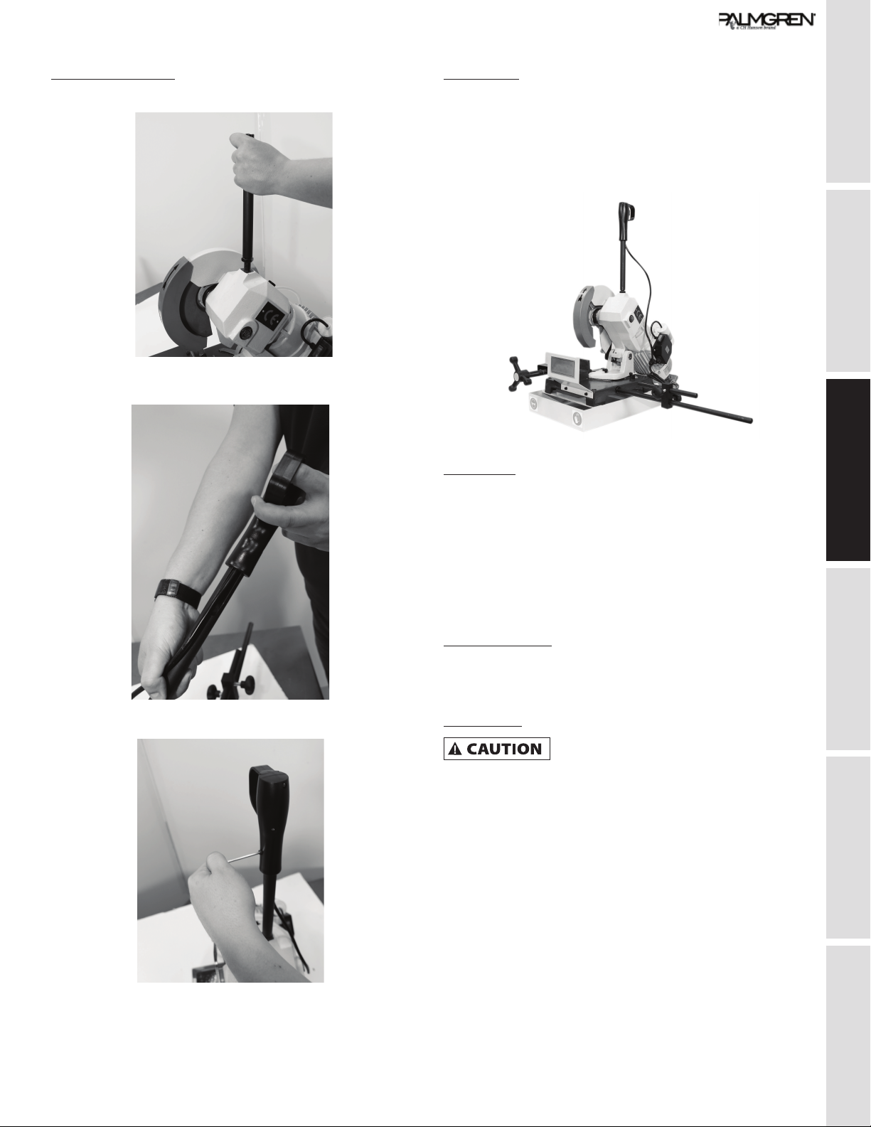
Assembly: Handle
1. Screw the shaft (item #22) into the top of the saw.
2. Slide the handle (#25) onto the shaft (#22). Ensure the wire
from the handle fits with the slot in the shaft.
3. Tighten the set screw to lock handle to shaft.
4. The nut on the end of the rod can be used to lock the handle
to face the desired direction.
Depth stop
1. Slide long bar stopper rod into bar stopper, and tighten the
handle screw.
2. Position and screw into the side of the blue base of the saw.
3. Use provided nut to lock the bar stopper in the upright
position.
Saw blade
Select the appropriate blade for the job as shown in “Blade
Selection” on page 9.
To install the blade, remove the screw 33, keeping the motor-
blade block raised and rotate the mobile guard 31 backwards .
Unscrew the screw 29 counter clock wise , withdraw the flange
28 , insert the circular blade, making sure that the teething faces
the same direction as the arrow on the mobile guard. Then refit
flange 28 and screw 29.
Cutting Coolant
For the cooling of the circular blade , fill the tank with emulsion oil
obtained from a mixture of water and AGIP AQUAMET 700 EP oil
with a percentage of 5-7%
Lubrication
Do not operate this machine before
lubrication and ensuring proper oil level.
Failure to comply may damage the machine.
Fill the pump with 32# or 46# hydraulic oil as shown by the fill
indications.

TROUBLESHOOTING OPERATION ASSEMBLY / INSTALLATION SAFETY / SPECIFICATIONS GETTING STARTED
8
MAINTENANCE / REPAIR
OPERATION
Always wear safety glasses complying
with U.S. ANSI Z87.1 before beginning any
power tool operation.
To avoid injury from unexpected starting,
whenever changing the saw blade or
carrying out adjustments, switch the saw off and remove the
power cord from the mains outlet. To avoid injury to hands
when handling the saw blade, wear gloves whenever
necessary.
Do not operate before properly lubricating
the machine. Failure to lubricate before
using can damage the saw.
Cutting
Power at the main power switch must be
set to “O” (OFF) .
1. Ensure the correct power is being supplied to the saw.
2. Ensure proper coolant is available (see “Cutting Coolant” on
page 7).
3. Ensure stock is securely clamped in the vise.
Miter Gauge
Do not activate the saw if bolt #52 is not
tightened.
4. Set the angle between the saw blade and stock to be cut.
Loosen the bolt #52, in the parts list. See the following
figure. Rotate the saw head to the desired angle. An angle
scale is provided behind the saw head. And retighten the bolt
to lock into position.
5. To prepare the saw to cut, flip the main power, rocker switch
from the “O”, OFF, position to the “1” , ON, position (See the
following figure). This provides power to the microswitch that
must be pressed to spin the saw blade in the next step.
6. Press and hold the micro switch found in the top handle, and
the saw blade will begin to spin. Use the handle to slowly
lower the blade into the stock to make the cut. If the micro
switch is released the saw blade will not continue to rotate.
CHANGING BLADES
To remove and replace the saw blade:
1. Make sure the cold saw is disconnected from the power.
2. Hold the saw blade still, by lowering the blade into a piece of
wood set in the vise.
3. Unhook the guard rod (A) from the guard.
Blade
Guard
Blade Housing
A
B
4. Remove Allen head screw (B)
5. Use gloves to safely remove the saw blade.
6. Follow these steps in the reverse order with a new blade.
NOTE: The new blade will need to be broken in, before full use.

9
GETTING STARTED SAFETY / SPECIFICATIONS ASSEMBLY / INSTALLATION OPERATION TROUBLESHOOTING MAINTENANCE / REPAIR
BLADE SELECTION
NOTE: Best performance of worm screw worm wheel gearing is guaranteed when circular saw blades with drawing-holes are used.
Cutting Capcity (values in parentheses are in mm)
Cut
90º 1.18” (30) 2.56” (65) 2.17” x 2.17” (55 x 55) 1.77” x 2.76” (45 x 70)
45º 1.18” (30) 2.36” (60) 1.97” x 1.97” (50 x 50) 1.57” x 2.36” (40 X 60)
Blade Selection (values in parentheses are in mm)
Diameter 7.78” (200) 8.86” (225) 9.84” (250) 10.83” (275) 11.81” (300) 12.40” (315) 13.78” (350)
Thickness 0.07” (1.8) 0.07” (1.8) 0.08” (2) 0.10” (2.5) 0.10” (2.5) 0.10” (2.5) 0.12” (3)
b=0.39”-3.15”
(10-80)
g<(2)
t 0.12” (3) 0.12” (3) 0.12” (3) 0.12” (3) 0.12” (3) 0.12” (3) 0.12” (3)
z 7.87” (200) 9.06” (230) 9.84” (250) 11.02” (280) 11.81” (300) 12.60” (320) 13.78” (350)
b= 0.39”-3.15”
(10-80)
g=0.08”-0.16”
(2-4)
d=0.39”-0.71”
(10-18)
t 0.20” (5) 0.20” (5) 0.20” (5) 0.20” (5) 0.20” (5) 0.20” (5) 0.20” (5)
z 5.12” (130) 5.51” (140) 6.30” (160) 6.70” (170) 7.48” (190) 7.87” (200) 8.66” (220)
b= 0.39”-3.15”
(20-80)
g=0.16”-0.39”
(4-10)
d=0.71”-1.18”
(18-30)
t 0.31” (8) 0.31” (8) 0.31” (8) 0.31” (8) 0.31” (8) 0.31” (8) 0.31” (8)
z 3.15” (80) 7.48” (90) 3.94” (100) 4.33” (110) 4.72” (120) 4.72” (120) 5.51” (140)
d=1.18”-1.57”
(30-40)
t 0.39” (10) 0.39” (10) 0.39” (10) 0.39” (10) 0.39” (10) 0.39” (10) 0.39” (10)
z 2.36” (60) 2.76” (70) 3.15” (80) 7.48” (90) 7.48” (90) 3.94” (100) 4.33” (110)
d>1.57” (40) t 0.47” (12) 0.47” (12) 0.47” (12) 0.47” (12)
z 2.76” (70) 3.15” (80) 3.15” (80) 7.48” (90)
NOTE: t = tothing pitch, z = number of teeth

TROUBLESHOOTING OPERATION ASSEMBLY / INSTALLATION SAFETY / SPECIFICATIONS GETTING STARTED
10
MAINTENANCE / REPAIR
TROUBLESHOOTING GUIDE
Symptom Possible Cause(s) Corrective Action
Teeth breaking Coolant flow problem Ensure proper coolant flow; hoses unclogged; nozzles pointed
correctly, etc. Make sure coolant type is suitable for the
machine.
Material too hard Check the blade speed and the type of blade you are using.
Also be aware of feed pressure.
Blade not worn-in correctly With a new blade it is necessary to start cutting at half feeding
speed. After the wearing-in period (a cutting surface of about
300 cm2 for hard materials and about 1000 cm2 for soft
materials) the blade and feed speeds can be raised to normal
values.
Blade with excessively fine tooth pitch The swarf wedges into the bottom of the teeth causing
excessive pressure on the teeth themselves. Use a blade with
coarser tooth pitch.
New blade inserted in a partially
completed cut
The surface of the cut may have undergone work hardening.
When starting work again, use a lower blade speed and
reduced feed pressure. A tooth from the old blade may be left
in the cut: check and remove before starting work again.
Work piece not clamped firmly in place Any movement of the work piece during cutting can cause
broken teeth: check the vise, jaws and clamping pressure.
Rapid tooth wear Feed speed too slow The blade runs over the material without removing it: increase
feed speed.
Blade speed too high The teeth slide over the material without cutting it: reduce the
blade speed.
Insufficient coolant Check the coolant level and clean coolant lines and nozzles.
Incorrect fluid concentration Check and use the correct concentration.
Material defective The materials may present altered zones either on the
surface, such as oxides or sand, or in section, such as under-
cooled inclusions. These zones, which are much harder than
the blade, cause the teeth to break: Discard or clean these
materials.
Broken blade Blade speed too high Reduce blade speed.
Teeth in contact with material before
starting the cut
Always check the position of the blade before starting a new
job.
Insufficient coolant Check the coolant level and clean coolant lines and nozzles.
Cuts not straight Feed speed too strong Reduce feed speed.
Blade not perpendicular to workpiece. Adjust blade tracking according to instructions. If this proves
unsuccessful, contact JET technical support.
Green pilot lamp not
lit when ON button
pressed
No incoming power Check connections at machine and power source.
Lamp fuse or bulb is out Replace fuse/bulb.

11
GETTING STARTED SAFETY / SPECIFICATIONS ASSEMBLY / INSTALLATION OPERATION TROUBLESHOOTING MAINTENANCE / REPAIR
Symptom Possible Cause(s) Corrective Action
Motor will not turn Emergency stop engaged Rotate Emergency Stop button to disengage.
Electrical power supply Check: the phases; the cables; the plug; the socket. Also
check that the motor connections are in place.
Trigger switch not activating Check that socket/plug connection from handle to motor is
inserted correctly; check micro-switch in trigger.
Transformer Check that the voltages are present both on the input and
output. Otherwise replace.
Magnetic contactor Check that the phases in it are present both on the input and
output, that it is not jammed, that it closes when powered and
that it is not causing short circuits. Change if any of these
problems are found.
Thermal relay Make sure it is closed, i.e. check that the phases are present
in input and output, that it is not causing short circuits and
responds when the reset coil is closed. If it has tripped to
protect the motor, check the amperage setting, re-set, and
check the motor. Change if necessary.
Motor Check that it has not burned out, that it turns freely and that
there is no moisture in the connection terminal board box. The
winding can be rewound or replaced by experienced motor
repair personnel.

MAINTENANCE / REPAIR TROUBLESHOOTING OPERATION ASSEMBLY / INSTALLATION SAFETY / SPECIFICATIONS GETTING STARTED
12
MAINTENANCE/REPAIR
Replacement of gear box oil
• Remove caps 38 and 19, let all the used oil flow out into a container which should have a label indicating the contents for the
purposes of disposal.
• Replace cap 19. Feed 0.2 litres of oil (as specified above) into the oil feed hole located on the upper part of the gear box and then
replace cap 38.
Lubrication of mobile parts of piece locking vice
Clean and grease the parts worked by the bench 2, the vice 9 and the vice screw 6.
Cleaning of the coolant tank: Filter check
Empty the coolant from the tank by means of the tap located on the rear part of the machine tank (after moving the liquid feed pipe
away from this). Collect the coolant in a container for future disposal. Clean out the shavings and the metallic powder, taking care not to
scatter this over the machine especially around the motor and the box containing the electrical equipment. Reconnect the pipe, check
filter 44 and if necessary replace it. Fill the tank with the amount and liquid stated previously.
Suggested Maintenance Schedule
FREQUENCY ( working hours ) OPERATION
1000 hrs or monthly Replace the oil in the gear box with AGIP BLASIA 220 oil (0.2 litres) or equivalent.
1000 hrs or monthly Lubrication of mobile parts in the piece locking vice
50 hrs or every 2 days Cleaning of the coolant tank and filter check
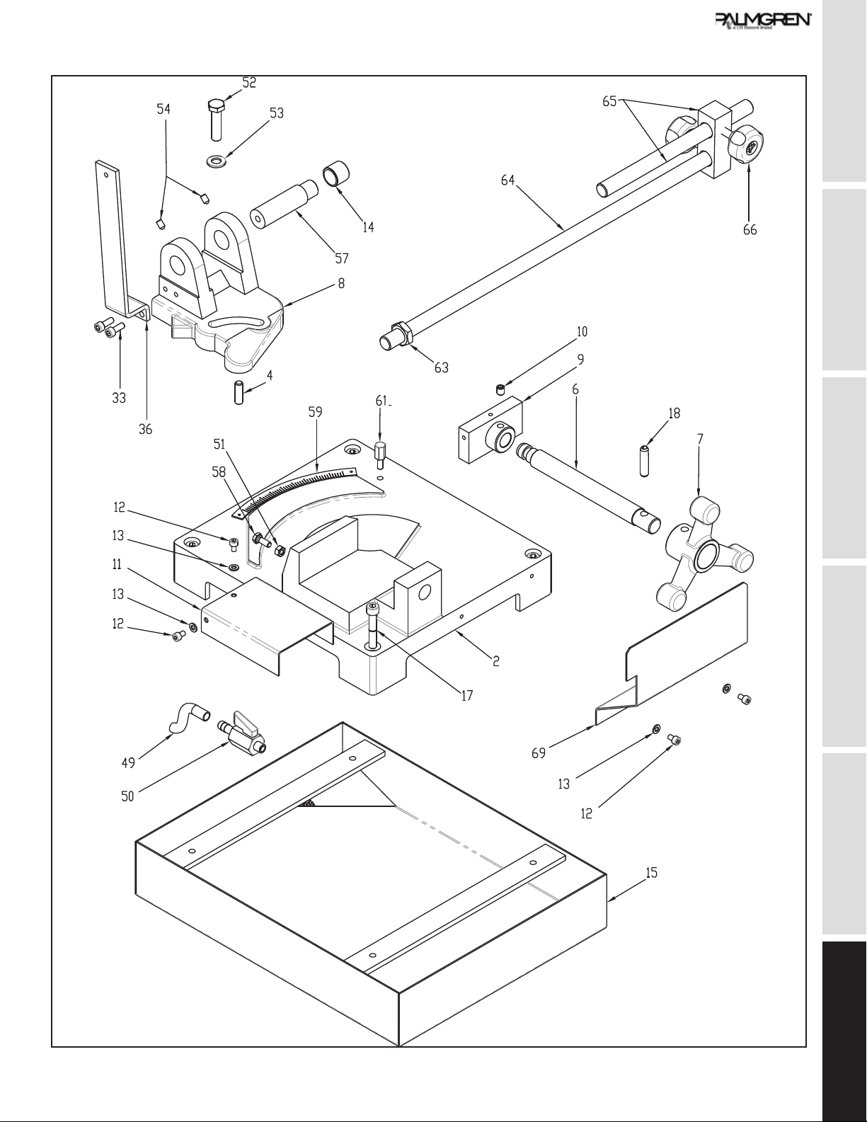
Parts List
GETTING STARTED SAFETY / SPECIFICATIONS ASSEMBLY / INSTALLATION OPERATION TROUBLESHOOTING MAINTENANCE / REPAIR
13

MAINTENANCE / REPAIR TROUBLESHOOTING OPERATION ASSEMBLY / INSTALLATION SAFETY / SPECIFICATIONS GETTING STARTED
14
POS. DESCRIPTION Part
Number
QTY
1 Snap Ring ?9 E * 1
2 Bench 9644230.01 1
3 Bearing 629-2RS ?9/26x8 * 1
4 Pin 8x26 DIN-6325 9644231.01 1
5 Not shown * 1
6 Vice screw 9644233.01 1
7 Vice handwheel ?140 3BR
BF 18 H7
9644234.01 1
8 Head carrying arm 9644235.01 1
9 Vice jaw 9644236.01 1
10 Dowel M8x10 DIN-915 UNI-
5925
9644237.01 1
11 Vice cover 9644238.01 1
12 HSHC screw M5x8 DIN-912
UNI-5931
* 4
13 Washer ?5 DIN-125-A * 2
14 Bush Eccentric 9644239.01 2
15 Tank 9644240.01 1
16 Not shown * 1
17 HSHC Screw M8x45 DIN-
912 UNI-5931
* 4
18 Spring Pin ?8x36 * 1
19 Oil level plug ?3/8? 9644241.01 1
20 Head 9644242.01 1
21 Spacer worm Screw 9644243.01 1
22 Head lever 9644244.01 1
23 Helical gear 9644245.01 1
24 Pin 6x6x40 9644246.01 1
25 Head lever handle with slot 9644247.01 1
26 Disk shaft 9644248.01 1
27 Disk 9644249.01 1
28 Disk flange 9644250.01 1
29 Disk fastening screw 9644251.01 1
30 Disk guard 9644252.01 1
31 Disk movable guard 9644253.01 1
32 Snap ring ?45 E DIN-471 * 1
33 HSHC screw M6x16 DIN-
912 UNI-5931
* 2
34 HSHC screw M6x16 DIN-
912 UNI-5931
* 2
35 Disk movable guard movable
rod
9644254.01 1
36 Disk movable guard fixed rod 9644255.01 1
37 HSHC screw M6x16 DIN-
912 UNI-5931
* 1
38 Oil filling cap ?3/8? 9644256.01 1
39 Key 5x5x30 DIN-6885 9644257.01 1
POS. DESCRIPTION Part
Number
QTY
40 Dowel M8x35 DIN-914 UNI-
5927
9644258.01 4
41 Switch box 9644259.01 1
42 Not shown * 1
43 Motor M80 V230/50 1F 4P
B4 HP1
9644261.01 1
44 Filter TE 250 FB 7 9644262.01 1
45 Splash ?30/42x7 9644263.01 1
46 Bearing 6205 ?25/52x15 * 1
47 Worm screw 9644264.01 1
48 Self-locking ring nut M16x1
DIN-981
* 1
49 Water pipe 9644265.01 1
50 Tap ?1/8? 9644266.01 1
51 Medium Nut M6 DIN-934
UNI-5589
* 1
52 HH screw M10x40 DIN-933
UNI-5739
* 1
53 Washer ?10 DIN-125/A * 1
54 Dowel 6x10 DIN-914 UNI-
5927
9644267.01 1
55 Not shown * 1
56 Stator 9644269.01 1
57 Head pin 9644270.01 1
58 HH screw M6x16 DIN-933
UNI-5739
* 1
59 Graduated sector 9644271.01 1
60 Splash guard 25-35-7 9644272.01 1
61 Stopper 9644273.01 1
62 Not shown * 1
63 Nut M16 DIN-934 UNI-5589 * 1
64 Bar stopper rod 9644275.01 1
65 Bar stopper 9644276.01 1
66 Bar stopper knob 9644277.01 2
67 HH screw M6x30 DIN-933
UNI-5739
* 2
68 Pump 9644278.01 1
69 Front cover 9644279.01 1
70 Nut M8 DIN-934 UNI-5589 * 4
71 Nut M6 DIN-934 UNI-5589 * 3
72 Nut M14 DIN-936 UNI-5589 * 1
73 Not shown * 1
74 Not shown * 1
75 Snap ring ?52 I * 1
76 Compensation Ring 9644282.01 1
77 Spring pin 6x16 DIN1481 * 1
78 Bearing 6204 - 2Z ?20/47x14 * 1
79 Not shown * 1

GETTING STARTED SAFETY / SPECIFICATIONS ASSEMBLY / INSTALLATION OPERATION TROUBLESHOOTING MAINTENANCE / REPAIR
15
POS. DESCRIPTION Part
Number
QTY
80 Fan MEC80 9644284.01 1
81 ”Self Locking Ring Nut
M25x1 5”
* 1
82 ”Belleville Washer 16x8 2x2
DIN-2093”
* 2
83 Bush ?6 9644285.01 2
219 HSFHC screw M4x8 DIN-
7991
* 1
220 Electrical cable 2x1 9644286.01 1
221 ”RH screw M2 9x13 DIN-
7981”
* 6
222 Micro switch of handle 9644287.01 1
223 Capacitor 25æFñ5% SH
450V Ac-50/60Hz
9644288.01 1
224 ”Fitting Pg 13 5” 9644289.01 1
225 Fitting Pg 9 9644290.01 1

PALMGREN WARRANTY
C.H. Hanson / Palmgren warrants their products to be free of defects in material or
workmanship. This warranty does not cover defects due directly or indirectly to misuse,
abuse, normal wear and tear, failure to properly maintain the product, heated, ground or
otherwise altered, or used for a purpose other than that for which is was intended.
The warranty does not cover expendable and/or wear part (i.e. v-belts, screws, abrasives,
jaws), damage to tools arising from alteration, abuse or use other than their intended
purpose, packing and freight. The duration of this warranty is expressly limited to the terms
noted below beginning from the date of delivery to the original user.
The Palmgren branded items carry the following warranties on parts:
All vises, clamps, positioning tables, tombstones, jack screws and vise
accessories - LIFETIME.
All bench grinders, drill presses, tapping machines, band saws, lathes, milling
machines, arbor presses, abrasive finishing machines and work stands - 3
YEARS.
The obligation of C.H. Hanson / Palmgren is limited solely to the repair or replacement, at
our option, at its factory or authorized repair agent of any part that should prove inoperable.
Purchaser must lubricate and maintain the product under normal operating conditions at
all times. Prior to operation become familiar with product and the included materials, i.e.
warnings, cautions and manuals.
Failure to follow these instructions will void the warranty.
This warranty is the purchaser’s exclusive remedy against C.H. Hanson for any inoperable
parts in its product. Under no circumstances is C.H. Hanson liable for any direct, indirect,
incidental , special or consequential damages including loss of profits in any way elated to
the use or inability to use our products. This warranty gives you specific legal rights which
may vary from state to state.
Palmgren - a C.H. Hanson Company
2000 N. Aurora Rd., Naperville, IL
60563
U.S.A.
or call 1-800-827-3398
Table of contents
Other CH Hanson Saw manuals


