CH X1 User manual

X1 External Power Supply
User Manual


Dear Client,
We are honored that you have chosen the CH X1 External Power Supply to ta e your existing CH Precision setup to the next level.
Our team made every effort to design and manufacture this top quality product and is proud to present it to you. We hope your
X1-powered system will bring you countless hours of emotion from your musical collection.
Before you start your musical journey, we indly as you to pay attention to the information contained within this manual. The X1,
as you will discover in the following pages, is a Swiss precision product designed for ultimate performance. However, in order to
reach sonic excellence, your unit needs to be setup and operated correctly and this what this manual is all about. If you have any
questions or require assistance, please don't hesitate to contact your authorized dealer.
We hope you will enjoy your CH Precision system for many years.
The Concert has just begun...
Cossy F.
Heeb T.


Table of contents
1 Technical highlights............................................................................................................................................................. 6
1.1 Electrical characteristics............................................................................................................................................... 7
1.1.1 Mains filtering................................................................................................................................................... 7
1.1.2 Transformers..................................................................................................................................................... 7
1.1.3 Rectifying and filtering secondary windings......................................................................................................... 7
1.1.4 Discrete regulation............................................................................................................................................. 7
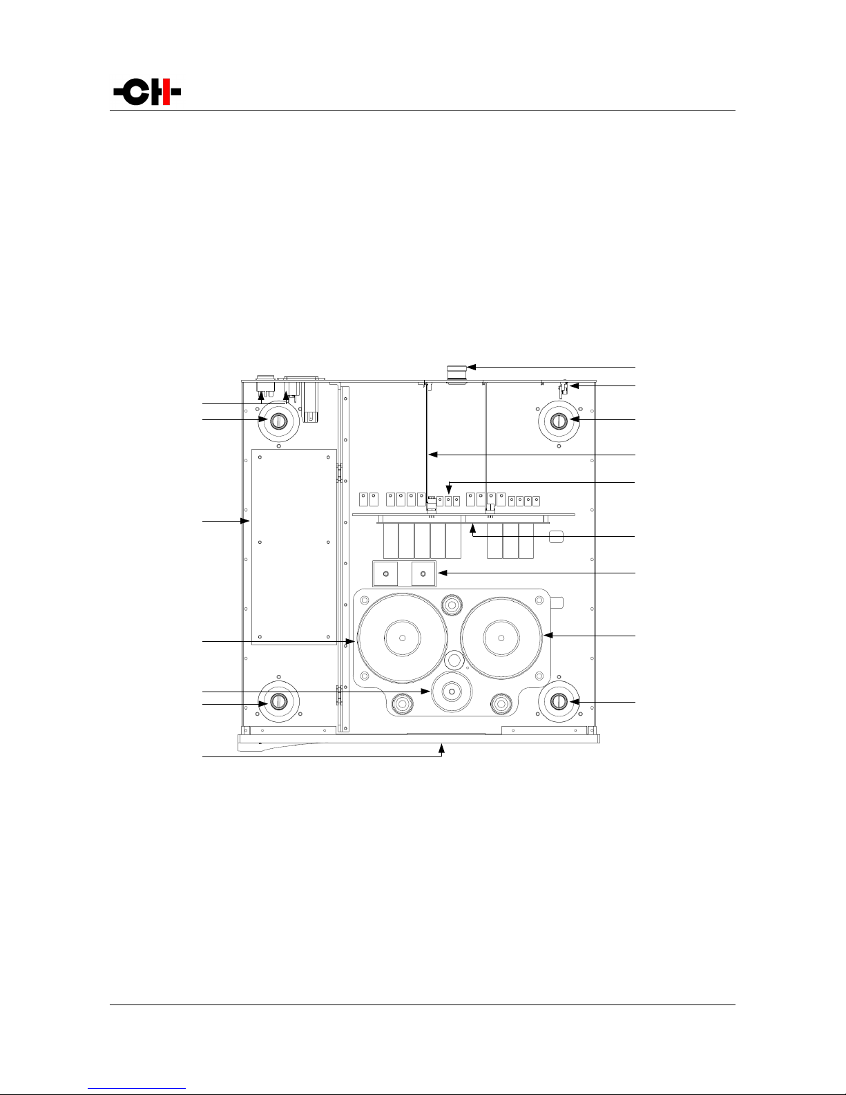
1.2 Mechanical construction.............................................................................................................................................. 8
2 Before use.......................................................................................................................................................................... 9
2.1 Pac age content......................................................................................................................................................... 9
2.2 Safety notice.............................................................................................................................................................. 9
2.3 User manual............................................................................................................................................................ 10
2.4 Mains supply............................................................................................................................................................ 10
2.5 Transport and pac aging........................................................................................................................................... 10
2.6 Cleaning.................................................................................................................................................................. 11
2.7 Maintenance and service........................................................................................................................................... 11
3 Installation....................................................................................................................................................................... 12
3.1 Unpac ing your unit................................................................................................................................................. 12
3.2 Positioning your unit................................................................................................................................................ 12
3.3 Connections.............................................................................................................................................................. 13
3.3.1 CONTROL board............................................................................................................................................... 14
3.3.1.1 USB port................................................................................................................................................. 15
3.3.1.2 Push-buttons........................................................................................................................................... 15
3.3.2 POWER SOURCE board..................................................................................................................................... 15
3.3.2.1 Power connector..................................................................................................................................... 15
3.3.3 Power cord receptacle and voltage selection...................................................................................................... 16
4 Operation......................................................................................................................................................................... 17
4.1 Front panel.............................................................................................................................................................. 17
4.2 Configuration........................................................................................................................................................... 18
5 Firmware update.............................................................................................................................................................. 19
5.1 Introduction............................................................................................................................................................. 19
5.2 Firmware update procedure...................................................................................................................................... 19
5.2.1 Preparing the firmware image.......................................................................................................................... 19
5.2.2 Updating the firmware..................................................................................................................................... 19
6 Troubleshooting................................................................................................................................................................ 21
7 Specifications.................................................................................................................................................................... 22
Rev 2.1 X1 User Manual 5

1 Technical highlights
CH products are proudly designed and manufactured in Switzerland by CH Precision Sàrl. Our engineers have put all their now-
how and ingenuity to bring you the X1, a top performance, ultra low-noise, high current capable, DC-regulated external power
supply capable of powering up to two CH Precision units.
An X1 fitted with two regulation boards can be used to power two CH Precision devices simultaneously (such as a C1 controller, a
D1 disc transport, a L1 line preamplifier or a P1 phonostage), with the advantage of dedicated transformers for analog and digital
sections, and cascaded voltage regulation. However, for ultimate performance, the X1 can be dedicated to power a single CH
Precision unit.
X1 main components
(1) Mains switch and power cord receptacle (on bac panel)
(2) Adjustment shafts and screws
(3) High noise-rejection mains filter
(4) Digital power supply transformer
(5) Standby power transformer (ensures green mode Standby)
(6) PMOLED display (on front panel)
(7) Power supply output connectors (one or two per X1), must be connected to C1 and/or D1 and/or L1 and/or P1
(8) USB A-type receptacle for firmware update
6 X1 User Manual Rev 2.1
(1)
(2)
(6)
(2)
(2) (2)
(3)
(7)
(9)
(4)
(5)
(13)
(8)
(11)
(12)
(10)

(9) Power supply regulation boards (one or two per X1)
(10) Motherboard
(11) Filtering board
(12) Rectifiers
(13) Analog power supply transformer
1.1 Electrical characteristics
The X1 is a high grade linear power supply delivering the analog and digital DC power supplies required by a C1, D1, L1 and a P1
on high current capable M23 19-poles connector(s). Input AC voltage can be set to 100V, 115V or 230V AC to accommodate local
mains supply.
1.1.1 ains filtering
The X1 transformer primary windings are individually filtered by massive RLC balanced networ s. Both common mode and
differential harmonics and bac ground noise get heavily attenuated. The critical analog power supplies are therefore isolated from
the noisy digital power supplies, leading to unprecedented micro-dynamics and signal-to-noise ratio.
1.1.2 Transformers
X1 houses no less than 3 magnetically shielded toroidal transformers, with static shields between primaries and secondaries:
•An overspecified transformer is dedicated to analog power supplies, holding multiple sets of secondary windings (one of
them being exclusively used generate the purest Mastercloc signal)
•The second overspecified transformer is dedicated to digital power supplies, capable of delivering high current pea s
required by high performance DSPs and FPGAs, without radiating noise
•A tiny transformer is used as standby transformer to ensure green standby mode, meeting the latest energy saving
regulations
All three transformers are mounted on a separate steel plate which is isolated from the main aluminium base plate through silent
bloc s.
1.1.3 Rectifying and filtering secondary windings
A large array of low ESR capacitors follows fast switching rectifier bridges on all secondary windings. This creates a proper energy
reservoir responding extremely fast to high current demands, ensuring the transformers wor under minimal stress condition,
leading to less radiated noise and excellent component preservation over time.
1.1.4 Discrete regulation
Discrete (power-transistor and op-amp based) ultra low noise regulators are used throughout the regulation stages of the X1 and
special care has been paid to the Mastercloc power supply, which is completely decoupled from all other power supplies. This
ensures an ultra-low jitter cloc source for the whole system.
Rev 2.1 X1 User Manual 7

When the X1 external power supply is connected to a CH Precision device, the latter's internal power supply is turned off (only the
standby transformer remains active, requiring its mains lead to remain plugged in). Turning the internal power supply off ensures
that no power supply induced noise or radiations are generated inside that unit, thus permitting optimal operating conditions for
the circuitry.
Moreover, all DC-regulated voltages delivered by the X1 get regulated once more inside the CH Precision unit it powers, leading to
vanishingly low noise floor.
1.2 echanical construction
The X1 external power supply is assembled from high-quality aluminium and steel elements with no visible screws on the front, top
and side panels. The front panel, base, side panels and top cover are machined from aluminium. The mains filtering section is
isolated from the rest of the machine in a dedicated compartment to avoid any contamination of unclean power distribution grid to
the secondary windings of the transformers by radiated noise. Pin assembly of all chassis elements provides smooth joints between
elements while screws every 6cm ensures protection against electromagnetic interferences. First class mechanical and chemical
surface treatments provide the luxury finish of the X1.
Four steel feet support the unit. Each feet ends with a elastomer ring to sit on delicate surfaces but is also equipped with a height
adjustable steel spi e to fine tune unit positioning. Horizontal adjustment is done with the provided screwdriver through the four
adjustment shafts accessible from the top of the unit. In addition to providing convenient horizontal adjustment from the top of the
unit, the shafts also serve as vibration evacuation channels for any stac ed unit. Special shaft covers are provided to interface with
the spi es of the stac ed unit. Any vibration from the upper unit is transmitted by the shaft cover to the shaft and from the shaft to
the lower unit feet or spi e, forming a privileged path for vibrations evacuation.
8 X1 User Manual Rev 2.1

2 Before use
Please read this manual carefully before ma ing connections or operating your X1. After reading this manual, please store it in an
accessible place for future reference. If after reading this manual you feel unsure about how to ma e connections or how to
operate the unit, please contact your authorized dealer for assistance.
2.1 Package content
Ma e sure that the pac age content is complete. If not, please contact your authorized dealer. Your pac age should contain:
•The X1 external power supply unit
•One or two Power Lin Cables (configuration-dependent)
•A power cord
•Four adjustment steel spi es
•A suction cup (used to unscrew the top covers)
•An accessory box containing:
◦a spi e adjustment screwdriver
◦a Torx 10 screwdriver
◦four stac ing covers
◦a USB stic containing the latest CH Precision firmwares.
◦four CH Support Discs
Please store the pac aging for future transportation. Chec your X1 external power supply for apparent damages. In case of
damage, please contact your authorized dealer. If your X1 is still very cold following transport, please let it warm up to room
temperature before powering it up (in order to avoid condensation inside the unit).
2.2 Safety notice
Ma e sure to observe the following rules:
•Install your X1 external power supply unit on a stable base
•Do not install your X1 near water
Rev 2.1 X1 User Manual 9

•Always handle with care. The X1 is quite heavy, so as someone to help you handle it
•Do not expose the unit to any ind of liquid
•Do not install in direct sunlight or near any heat source such as radiators or other apparatus generating heat
•Do not install in a confined space and allow sufficient airflow around the unit
•Do not operate under high ambient temperature (>40°C) or with extremely high humidity such as in humid cellars
•Only use options and accessories specified or recommended by the manufacturer
•Only connect CH Precision compatible devices (such as C1, D1, L1 or P1)
•Do not open the unit nor try to service it. Do not install any option board yourself. Always refer to a qualified technician
for service, maintenance or hardware upgrades. Failure to do so will void the unit's warranty
2.3 User manual
Please read this manual carefully before ma ing connections or operating your X1 external power supply. Keep this manual at
hand for future reference. If after reading this manual you feel unsure of how to ma e connections or how to operate the unit,
please contact your local authorized dealer.
2.4 ains supply
Ma e sure to use 3 terminals (phase, neutral and earth) power cords. Ma e sure that the mains voltage selection at the bac of
the unit matches your local mains voltage.
Always disconnect your X1 external power supply from the AC wall soc et in the following cases:
•When ma ing connections (it is also recommended to disconnect the rest of the system from AC wall power)
•When cleaning the unit
•During thunderstorms
•When unused for a long period of time
Ma e sure your X1 external power supply is disconnected from other CH Precision devices when running a self-test.
2.5 Transport and packaging
The X1 external power supply must always be stored in its original pac aging for transportation. Doing so will ensure optimal level
10 X1 User Manual Rev 2.1

of protection to your unit. Therefore, eep the pac aging in a dry and clean place for future use.
Besides, we recommend to remove the adjustment spi es and to put them into the X1 box for transportation. Indeed, vibrations
during transport may cause the adjustment spi es to move from their fully retracted position. There is a ris of scratching the piece
of furniture the unit is installed onto if the spi es are not fully retracted.
2.6 Cleaning
Use a soft, dry towel or cloth for cleaning. Never use any solvent or liquids as they may damage the surface or penetrate inside
the unit.
2.7 aintenance and service
The X1 external power supply contains no user serviceable parts. Do not try to open, modify or repair your X1 yourself. This will
void any warranty. Your X1 must be chec ed by a qualified technician in any of the following cases:
•The unit is not functioning properly
•The mains cable or the power cord receptacle is damaged
•The Power Lin Cable or M23 19-poles connector is damaged
•The unit has been dropped or presents external damage
•The X1 has been exposed to liquids (such as rain) or un nown substances
Rev 2.1 X1 User Manual 11

3 Installation
3.1 Unpacking your unit
Unpac the X1 external power supply and store the pac aging for future transportation. Be careful when lifting the X1 as the unit
is heavy (over 20 g). Get someone to help you if necessary. When unpac ing and installing the X1, ta e care not to damage the
high quality surface treatments.
3.2 Positioning your unit
When delivered from factory, the X1 external power supply's four feet sit on elastomer rings, ensuring both scratch-protection for
the base on which the unit sits, as well as safe anti-slipping unit positioning.
But a more advanced vibration-channeling mechanical coupling can be implemented, than s to the steel spi es and the polymer
support discs provided with the X1. To use this optimal coupling, simply go through the following steps:
1. Place the X1 unit on a stable base at its approximate final position, for instance in your preferred audio rac . Ma e sure
cooling air is able to freely flow around the unit.
2. Gently lift the unit's corners and insert a support disc under each foot. The foot's elastomer ring should disappear in the
support disc's groove when properly placed. Carefully chec all four feet perfectly fit in each support disc before pursuing
any further. The unit should stably rest on its feet at that point.
3. Unscrew the four top covers from the X1's shafts with the provided suction cup. Be careful not to scratch their delicate
finish.
4. Insert the adjustment spi es into each adjustment shaft.
5. Softly screw cloc wise each adjustment spi es into the shaft with the provided screwdriver, until any resistance is felt (just
before the unit's corner starts to lift).
6. Then screw cloc wise each spi e by the same amount (for instance two full turns).
7. If the base is flat, the unit should be stable and horizontal. If not, correct the unit's stability and horizontality by turning
cloc wise or anti-cloc wise the required spi es.
8. If no CH Precision unit is to be stac ed on top of the X1, screw the four top covers bac . Otherwise, screw the four
polymer stac ing caps instead, and gently lay down the unit to be stac ed on top of it. Be very careful that both units are
perfectly aligned in order not to scratch the X1's top plate with the other unit's feet. Repeat steps 3 to 8.
12 X1 User Manual Rev 2.1

Adjustment shafts, feet and spikes
(1) Adjustment shafts. Insert spi es and use the provided screwdriver to adjust individual feet spi es
(2) Feet
(3) Adjustment spi e heads (when inserted into adjustment shafts)
(4) Adjustment spi e
Never stac any component other than CH components on your X1. Never use the aluminum shaft covers (top covers) when
another CH component is to be stac ed on top of your X1.
Shaft covers (left: stacking cover, right: top cover)
3.3 Connections
This section provides information on how to connect your X1 external power supply to your system. As the X1 can be configured to
power one or two CH Precision devices, it can be fitted with a single or two POWER SOURCE boards (the picture below shows an X1
with two POWER SOURCE boards).
Rev 2.1 X1 User Manual 13
(1)
(1)
(1)
(1)
(2)
(3) (3)
(3) (3)
(2) (2)
(2)
(4)

Rear panel connections
(1) USB port for software upgrades.
(2) Push-button for software upgrades and parameter value editing
(3) Push-button for X1 self-test and parameter selection
(4) Power Lin Cable connector to power a CH precision unit, such as C1, D1, L1 or P1
(5) Power Lin Cable connector to power a CH precision unit, such as C1, D1, L1 or P1 (optional)
(6) Power on/off switch
(7) Power cord receptacle
(8) Mains fuse and voltage selection
3.3.1 CONTROL board
The CONTROL board is factory installed into the X1. It provides a USB port for software updates and two push-buttons for
configuration. The following drawing shows the layout of the bac panel of the CONTROL board:
CONTROL board back panel layout
14 X1 User Manual Rev 2.1
(1) (4) (5) (6)
(8) (7)
(2) (3)

3.3.1.1 USB port
The USB port on the CONTROL board is dedicated to the firmware update of the X1 unit. Do not use it for any other purpose. For
more information on unit firmware update, please refer to chapter 5 of this manual.
3.3.1.2 Push-buttons
Two push-buttons allow access to four functions, depending when they are pushed. Detailed information on that topic is provided in
chapter 4 (Operation) of this manual.
3.3.2 POWER SOURCE board
As an X1 can be used to power one or two CH Precision units, it can be fitted with one or two Power source boards. Each board has
its own set of discrete regulators for analog and digital voltage rails. The following drawing shows the layout of the bac panel of
the POWER SOURCE board:
POWER SOURCE board back panel layout
3.3.2.1 Power connector
The interface between an X1 and a CH Precision unit is handled by the Power Lin Cable, plugged to the 19-poles connector at both
ends.
Ma e sure both X1 and X1-powered unit are turned off completely (Power on/off switch in the off position) before connecting the
two units together. Insert the Power Lin Cable plugs and secure them by fully tightening their outer ring.
Then both units can then be switched on (Power on/off switch in the on position). They will remain in standby until the X1-powered
device is ta en out of standby (by pushing its inner encoder, or from its remote control).
The X1's wa e up and standby operations are automatically ta en care of by signals exchanged between the units through the
Power Lin Cable, so no user action is required on the X1 once its power switch is in the on position.
Rev 2.1 X1 User Manual 15

3.3.3 Power cord receptacle and voltage selection
Ma e sure that the voltage selection is set to the correct value with respect to the AC mains voltage in your location. Connect the
power cord to the power cord receptacle and plug the power plug to an AC wall soc et only after all the other connections were
made.
16 X1 User Manual Rev 2.1

4 Operation
The X1 external power supply is designed to seamlessly integrate in a CH Precision setup. Once properly connected and set up, it
requires no user intervention to operate.
4.1 Front panel
Front panel elements
(1) Standby LED
(2) Display area (PMOLED display)
The standby LED lights up when the unit is in standby, i.e. when no connected CH Precision unit is being powered. It normally turns
off when the X1 is on, i.e. when at least one connected CH Precision unit is being powered. The LED can also be programmed to
remain on during operation. The PMOLED display can report status. Its color and operation can be adjusted to user's taste.
When an X1 powers a CH Precision device, the powered devices report it on their AMOLED display:
C1 display when X1-powered D1 display when X1-powered
(1) X1-powered icon
Rev 2.1 X1 User Manual 17
44.1 > 705.6 Hz -18.5 dB
AES EBU 1
JAUDIO IN
(1)
<
SACD 6ch
700:28:34
JINTERNAL
(1)
<
(1) (2)

4.2 Configuration
The PMOLED display and the LED behavior of the X1 are customizable through two push-buttons located on the control plate at the
bac of the unit. Each button has two different functions: a main function and an alternate function.
•The main function is called if the button is pushed while the X1 is in standby or on (i.e. powering a CH unit).
•The alternate function is called if the button is ept pushed while X1's main power switch is flipped from OFF to ON.
Function Button Description
Main 1 Setting selection (scroll across all settings, displaying their value)
2 Setting editing (scroll across all possible value of a particular setting)
Alternate 1 Self-test (chec that the X1 is wor ing well, displays a report of all tests)
2 Firmware update (start firmware update when a USB ey with valid f/w is plugged)
Control board push-buttons description
The table below lists all X1 settings and available values for each one:
SETTING POSSIBLE VALUES REMARKS
DISPLAY BRIGHTNESS 20%
40%
…
100%
Display brightness during the few seconds following a status modification
LED ON/OFF On
Off
Front LED state when the X1 is ON (i.e. powering at least one CH unit)
DISPLAY MODE Status
Off
What to display when the X1 is left idle for several seconds.
INFORMATION Firmware version
Slot left
Slot Right
Displays software and hardware related information about the X1
X1 settings
18 X1 User Manual Rev 2.1

5 Firmware update
5.1 Introduction
The X1's operation is managed by a microcontroller. This type of component runs a firmware which can be updated when needed,
for instance to support additional features or to correct bugs. The following sections describe how to update the firmware of your
X1 unit.
5.2 Firmware update procedure
5.2.1 Preparing the firmware image
Before doing the actual firmware update, it is necessary to prepare the firmware update image. Firmware update images are
available in the form of compressed .zip files from our website at www.ch-precision.com.
The following procedure shows how to prepare the firmware image:
1. Start by downloading the latest X1 firmware image from www.ch-precision.com
2. Prepare a blan , FAT32 formatted USB stic . Please note that some USB stic s are not properly detected by the USB
interface of the X1. CH Precision recommends the use of Sandis USB flash drives such as the one delivered with the unit.
3. Decompress the firmware image .zip file to the root of your USB stic
After doing so, your USB stic should contain the following file:
•X1_xxx.mc1: Firmware update file for X1 Micro-controller
where 'xxx' indicates the software version number.
Ma e sure this file is present at the root of your USB stic , and that only one version of this file is present. If multiple versions of
the same unit's firmware are present at the root of the USB stic , it can not be guaranteed which one will be loaded as the new X1
firmware.
5.2.2 Updating the firmware
Once the USB stic is ready with the appropriate file, you can proceed with the update of the X1 unit firmware. To do so, follow
these steps:
1. Turn off all CH Precision components connected to the X1.
2. Turn the X1 off by setting the Power on/off switch to off.
3. Disconnect any CH Precision unit from the X1.
Rev 2.1 X1 User Manual 19

4. Prepare and insert the USB ey containing the appropriate firmware image for your unit (as detailed above).
5. Keep the firmware update push-button (located next to the USB receptacle at the bac of the unit) pushed while
powering-up the unit (by setting the Power on/off switch to on).
6. The unit will start up in firmware update mode and will update its internal firmware with the image present on the
USB stic . Do not interrupt or unplug the unit until the firmware update is finished. This typically ta es about 5
seconds.
7. Once the firmware update is finished, the units goes into standby mode. You can then remove the USB stic .
8. To verify that the firmware update was successful, you can press the other push-button once. The current firmware in
use will be displayed.
9. Switch off the X1 unit (Power on/off switch to off) before plugging bac CH Precision component(s) to be powered by
the X1 unit.
Note: The firmware update process can last several seconds, do NOT interrupt it!
If the firmware update procedure fails, try to download the latest software images from www.ch-precision.com, use another USB
stic , and rerun the firmware update procedure (don't forget to prepare the software update files and USB stic accordingly). If
failure persists, contact your authorized dealer.
20 X1 User Manual Rev 2.1
Table of contents