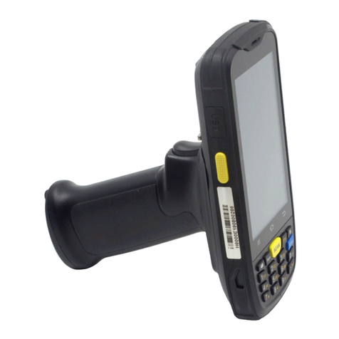
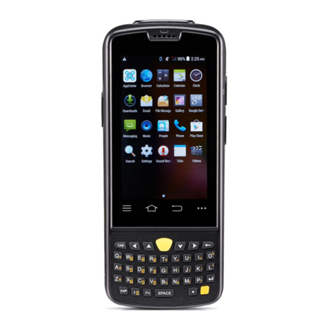
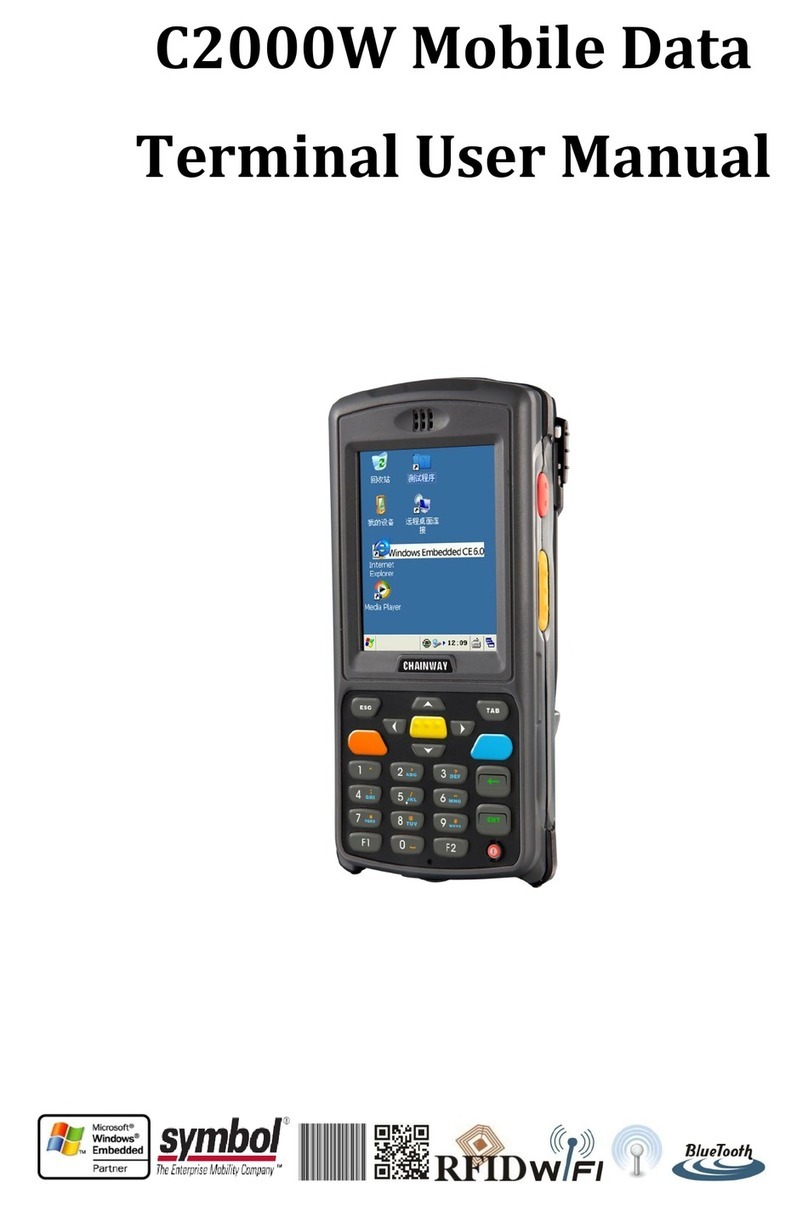
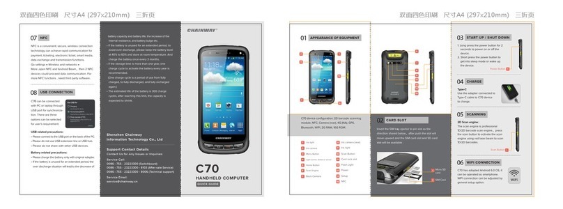
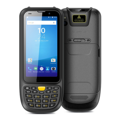
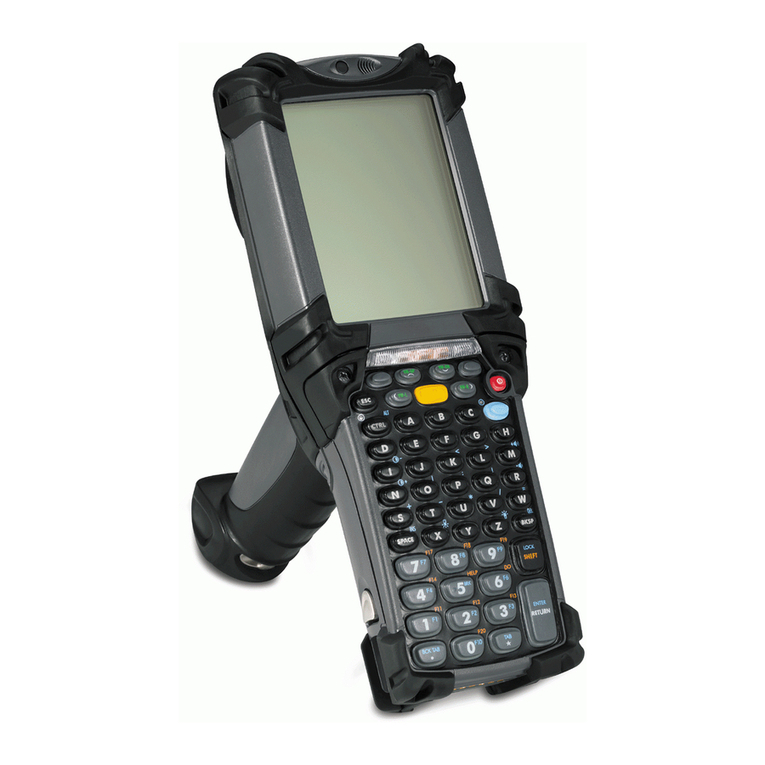
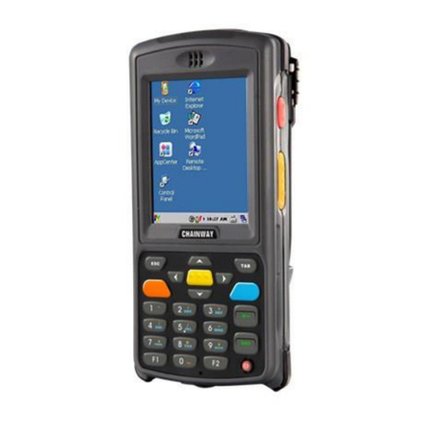
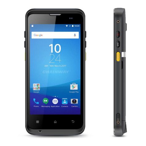
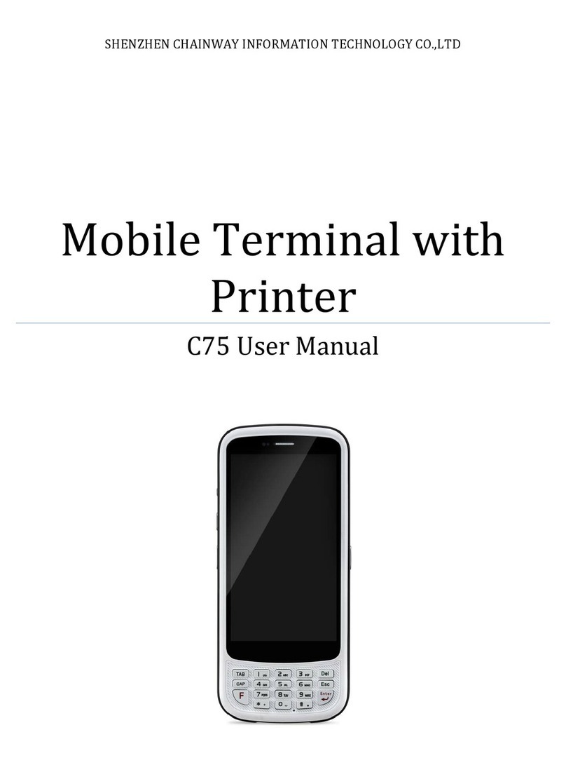
Chainway C5000U User manual

C5000U Mobile Data Terminal
User’s Manual
V1.03


C5000 Series Mobile Data Terminal
User’s Manual
P-C5000-20110803
Rev. C
August 2011

I
Table of Contents
TABLE OF CONTENTS...................................................................................................................................................... I
CHAPTER 1 OVERVIEW ............................................................................................................................................... 1
1.1 FEATURES AND STRUCTURE.............................................................................................................................................. 1
1.2 PACKAGE AND ACCESSORIES ............................................................................................................................................ 4
CHAPTER 2 GETTING STA RT E D ................................................................................................................................... 6
2.1 BATTERY INSTALLATION AND RECHARGING .......................................................................................................................... 6
2.2 SD CARD (TF CARD)...................................................................................................................................................... 7
2.3 SIM CARD ................................................................................................................................................................... 8
2.4 STANDBY/WAKEUP ........................................................................................................................................................ 8
2.5 RESTART ...................................................................................................................................................................... 8
2.6 UPDATE FIRMWARE /RESTORE TO FACTORY SETTINGS .......................................................................................................... 9
CHAPTER 3 SYSTEM SETTINGS...................................................................................................................................10
3.1 DESKTOP ................................................................................................................................................................... 10
3.2 TASKBAR .................................................................................................................................................................... 10
3.3 INPUT METHOD .......................................................................................................................................................... 11
3.4 CONTROL PANEL.......................................................................................................................................................... 12
CHAPTER 4 FUNCTION MODULES .............................................................................................................................15
4.1 BARCODE SCANNER........................................................................................................................................................ 15
4.1.1 1D Barcode Scanner........................................................................................................................................ 15
4.1.2 2D Imager....................................................................................................................................................... 15
4.1.3 Scanning Direction.......................................................................................................................................... 16
4.2 UHF READER ............................................................................................................................................................. 17
4.2.1 Parameters ........................................................................................................................................................ 17
4.2.2 UHF Tags............................................................................................................................................................ 17
4.2.3 UHF Sample & Functions ................................................................................................................................... 18
4.3 WIFI......................................................................................................................................................................... 23
4.3.1 WiFi Configuration.......................................................................................................................................... 23
4.3.2 IP Address Setting........................................................................................................................................... 25
4.3.3 WiFi auto Connecting ..................................................................................................................................... 26
4.4 GPRS ....................................................................................................................................................................... 27
4.4.1 Create and Configure Connection................................................................................................................... 27
4.4.2 Connect and Disconnect with GPRS................................................................................................................ 29
4.5 BLUETOOTH................................................................................................................................................................ 30
II
4.6 GPS ......................................................................................................................................................................... 31
4.7 CAMERA .................................................................................................................................................................... 31
CHAPTER 5 SYNCHRONIZATION AND UPDATE ...........................................................................................................32
5.1 SYNCHRONIZATION WITH PC.......................................................................................................................................... 32
5.1.1 Install Microsoft ActiveSync............................................................................................................................ 32
5.1.2 Install Device Driver ........................................................................................................................................ 33
5.2 INSTALL APPLICATIONS.................................................................................................................................................. 33
5.3 UPDATE OPERATION SYSTEM ......................................................................................................................................... 33
5.3.1 Copy System Files to SD Card.......................................................................................................................... 33
5.3.2 Update OS for Windows CE ............................................................................................................................ 33
5.3.3 Install drivers and default applications........................................................................................................... 34
CHAPTER 6 GUIDE FOR DEVELOPMENT .....................................................................................................................35
6.1 DEVELOPMENT ENVIRONMENT SETTINGS ......................................................................................................................... 35
6.1.1 Install C5000 SDK ............................................................................................................................................ 35
6.1.2 Create C++ MFC Project (VS2005)................................................................................................................... 37
6.2 EXTENDED SERIAL PORT INSTRUCTIONS ........................................................................................................................... 40
CHAPTER 7 MALFUNCTION AND REPAIR ...................................................................................................................41
7.1 EQUIPMENT AND SYSTEM PROBLEMS .............................................................................................................................. 41
7.2 SCANNING PROBLEMS .................................................................................................................................................. 41
7.3 RFID PROBLEMS ......................................................................................................................................................... 42
7.4 NETWORK AND COMMUNICATION PROBLEMS ................................................................................................................... 42
CHAPTER 8 MAINTENANCE .......................................................................................................................................43
CHAPTER 9 AC ADAPTER & BATTERY SAFETY.............................................................................................................44
CHAPTER 10 CERTIFICATION & CONFORMITY ...........................................................................................................46
10.1 CERTIFICATION:......................................................................................................................................................... 46
10.2 CONFORMITY:........................................................................................................................................................... 46

III
○
C2011 by Chainway Information Technology Co., Limited.All rights reserved.
No part of this publication may be reproduced or used in any form, or by any electrical or mechanical
means, without permission in writing from Chainway. This includes electronic or mechanical means, such
as photocopying, recording, or information storage and retrieval systems. The material in this manual is
subject to change without notice.
The software is provided strictly on an “as is” basis.All software, including firmware, furnished to the user
is on a licensed basis. Chainway grants to the user a non-transferable and non-exclusive license to use
each software or firmware program delivered hereunder (licensed program). Except as noted below, such
license may not be assigned, sublicensed, or otherwise transferred by the user without prior written
consent of Chainway. No right to copy a licensed program in whole or in part is granted, except as
permitted under copyright law. The user shall not modify, merge, or incorporate any form or portion of a
licensed program with other program material, create a derivative work from a licensed program, or use a
licensed program in a network without written permission from Chainway.
Chainway reserves the right to make changes to any software or product to improve reliability, function, or
design.
Chainway does not assume any product liability arising out of, or in connection with, the application or use
of any product, circuit, or application described herein.
No license is granted, either expressly or by implication, estoppels, or otherwise under any Chainway
intellectual property rights.An implied license only exists for equipment, circuits, and subsystems
contained in Chainway products.
Bluetooth is a registered trademark of Bluetooth SIG. Microsoft, Windows andActiveSync are either
registered trademarks or trademarks of Microsoft Corporation. All other product or service names are the
property of their respective owners.
Chainway Information Technology Co., Limited.
6/F, Building A, Tsinghua Information Harbor,
Technology Park, Nanshan, Shenzhen 518057
www.chainway.net


1
Chapter 1 Overview
This chapter introduces the overview of our device, such as features, structure, accessories and so on.
1.1 Features and Structure
Please refer to Table 1-1 about standard hardware configuration and specifications.
Table 1-1 Standard Configurations
Feature
Parameters
CPU Samsung ARM920T@533MHz
Memory 128MB RAM/1GB Flash
OS Microsoft WinCE 6.0 Pro
Wireless Communication WIFI, supports IEEE 802.11b/g protocol
Display
TFT touch screen
Resolution: 240 x 320
Color 3.2-inch QVGA, TFT-LCD, 65K colors
Transflective screen (sun view) optional
Keypad 26 keys and 1 Standby/Wakeup button on the keyboard and 4 side keys;
Side keys and F1/F2/F3/F4/F5 can be customized
Ports Mini USB (5PIN, USB 2.0)
IO port (14PIN, supports RS232)
Extension Slots SIM, PSAM
Micro SD (TF), supports maximum of 8G capacity
Speaker 0.5W output
Battery
(Power)
Standard Battery: 3.7V 3240mAh rechargeable Li-ion polymer battery
Extended Battery (Optional): 3.7V 2000mAh rechargeable Li-ion polymer
battery
Standby Current : <5mA
Temperature Operating Temperature : -20°C to +50°C
Storage Temperature : -25°C to +70°C
Operating Environment Dropping Survive : With stands 1.5m drop to concrete (six sides)
Rolling Survive : 1,000 times, 0.5 meter, rolling by six contact surfaces
Sealing Environment : IP64 (water- and dust-proof)
Weight Weight : <400g (including Standard battery)
Dimensions 186.5mm x 75mm x 38.9mm (with 4000mAh battery)

2
Please refer to Figure1-1-1 (Front), Figure1-1-2 (Back), Figure1-1-3 (Bottom) and Table1-2 about
structure.
Figure1-1-1 Front

3
Figure1-1-2 Back
Figure1-1-3 Bottom
The keypad consists of 26 buttons and 1 Standby/Wakeup button. There are 9 buttons, including 4 side
buttons and F1/F2/F3/F4/F5 on keyboard can be customized.
Please refer to Figure1-1-4 and Table 1-2 about the keyboard.
Figure1-1-4 Keyboard
Table1-2 Keyboard Description
Button
Description
F6 and F7
Move up, down, left and right
Enter key

4
Numbers
Backspace
F8 button
F1-F5 can be customized
Standby/Wakeup
1.2 Package and Accessories
Please refer to Table 1-4 about the Accessories.
Table1-4 Accessories List
Name
Figure
Description
Quantity
ACAdapter
Charge the battery 1
USB Cable
Synchronize with PC 1
Stylus
For touch screen operation 1
Battery
Li-ion polymer battery;
3240mAh 1

5
Serial Cable
Communicate with PC by
serial port Optional
Docking Station
(Charging Cradle)
Charge the device and
a spare battery Optional

6
Chapter 2 Getting Started
This chapter introduces basic operations to use the mobile data terminal, such as installation of battery,
SD Card and SIM Card, and Standby/Wakeup.
2.1 Battery Installation and Recharging
Battery installation steps (Figure2-1-1):
1) Unscrew to open the back cover with screwdriver.
2) Open the back cover.
3) Insert the battery; bottom first, into the battery compartment in the back.
4) Close the back cover.
5) Fasten the screws.
Figure2-1-1 Battery Installation Steps
Note: The C5000 Series ships with a 4000 mAh battery;
Position the battery correctly, with the battery charging contacts on top of the charging
contacts in the battery compartment.

7
Battery Recharging
1) UseAC Adapter to recharge by 220VAC power sockets.
(Figure2-1-2):
There are two methods to recharge battery:
2) Use USB cable to recharge by PC.
Figure2-1-2 Battery Recharging
LED Indicators
Note:
1. If the terminal standby, the LED indicators will not on no matter charging or not.
2. When battery very low till cannot turn on, please charge at least 30 minutes, then try to turn on; when
charging, the terminal would perform in turns like this: no response->display “Low battery”->can be
turned on->full battery
:
The LED indicators are on the upper right of the terminal, totally 3 LEDs.
1) When charging, the left 2 LEDs on, as Figure2-1-3;
2) When battery full, only the middle LED on, as Figure2-1-4;
3) When battery low, only the right LED on, as Figure2-1-5;
2.2 SD Card (TF Card)
Attention: The Micro SD card is standard accessory, which contains backup system firmware;
please do not pick it out,change its data, or format it without guidance by factory.
SD card installation steps:
1) Ensure the device is power off and in non-recharging status.
2) Unscrew the battery cover and then open the back cover.
3) Take out battery.
4) Place the SD card correctly, pay attention to the positions (Figure2-2-1, the slot at right).
5) Place the battery back and close the back cover.

8
6) Fasten the screws.
After the SD card is installed successfully, you can see an
icon named “Storage Card” when open “My Device”. You
can open it to get the files stored.
Figure2-2-1 SIM Card & SD Card Slot Figure2-2-2 Storage Card Icon
2.3 SIM Card
The SIM card installation steps are similar with SD card:
1) Ensure the device is power off and in non-recharging status.
2) Unscrew the battery cover and then open the back cover.
3) Take out battery
4) Place SIM card onto SAM2 slot (Figure2-3, the middle slot), push the lid downward and open it, then
place the SIM card correctly into the slot and push the lid upward to fasten.
5) Place back the battery and close the back cover.
6) Fasten the screws.
Please refer to chapter 4 “GPRS” to get how to use SIM card.
2.4 Standby/Wakeup
There is a red button on keyboard; it is the Standby/Wakeup button.
You can press this button to switch the status Standby or Wakeup. When standby, the screen will be dark
and all modules stop working. The standby current is less than 5mA.
Note: It is better to standby when recharging, then the battery will be full faster.
Attention: do not press this button frequently within a short period of time, which may cause damages to
the screen and data.
2.5 Restart
If you want to restart the mobile data terminal, please use the stylus to insert into the reset hole between

9
F4 and F5 on keyboard, hold on for seconds, and then the device will restart.
Note: the restart method above is cold start, and there is no warm start method for this device.
2.6 Update firmware / Restore to Factory Settings
1) Before updating or resetting, make sure the micro SD card is in.
2) If you want to restart the mobile data terminal, please use the stylus to insert into the reset hole
between F4 and F5 on keyboard, hold on for seconds, and then the device will restart.
3) When it restarted, press F1 when progress bar shows 0%, there will be a menu as Figure2-6-1, press
direction buttons to choose
Update OS
,then press enter button (yellow button), and the system will
update or restore to factory; it depends on the backup firmware in SD card to update or restore.
4) If you just want to enter Windows without any change, please choose
Start OS.
5) See more in 5-3 about updating.
Attention: do not choose Restore factory settings to restore, which is a reserved function.
Figure2-6-1

10
Chapter 3 System Settings
This chapter introduces system settings and operations on Windows CE.
3.1 Desktop
After starting the device, its default view is desktop (Figure3-1-1). You can click the icons or shortcuts on
desktop by stylus. If touch the screen for a while by stylus, it will be as right click by mouse on PC, you
can see the right-click menu (Figure3-1-2).
Figure3-1-1 Desktop Figure3-1-2 Right-click Menu
3.2 Taskbar
The taskbar is on the bottom of screen. It displays on-going tasks (Figure3-2-1).
Figure3-2-1 Taskbar
Start Menu: on the left of task bar, you can see program list in it (Figure3-2-2).
Figure3-2-2 Start Menu

11
Time: display current time; when double click, it will popup the calendar, and you can
change the date, the time and the time zone.
On-going Task Menu: on the right of task bar, displays all on-going tasks after clicking, and you can
switch tasks from here (Figure3-2-3).
Figure3-2-3 On-going Task Menu
3.3 Input Method
1) Input from keyboard: input numbers only by default;
2) Input by soft keyboard: click the keyboard icon on task bar, check the “Keyboard” (Figure3-3-1), it
will pop up the soft keyboard (Figure3-3-2), you can type letters from it.
Figure3-3-1 Check Keyboard Figure3-3-2 Soft Keyboard
There are two methods for inputting capitalized letters;
a) Press on soft keyboard and you can input capital letters and tap again to go back to
lower case status (Figure3-3-3).
b) Click and the soft keyboard switch to capital letter input, after a capital letter is input, the soft
keyboard will restore to lower case (Figure3-3-4).
Figure3-3-3 Press CAP Figure3-3-4 Press Shift
If you need to input symbols, click and select the ones you desire to input. When it’s done, click
to restore to normal (Figure3-3-5).

12
Figure3-3-5 Open Control Panel
3.4 Control Panel
Open control panel from start menu (Figure3-8), you can see system settings in it (Figure3-4-1).
Figure3-4-1 Control Panel
The setting applications are listed as Table3-1.
Table3-1 System Settings List
Application
Description
Set internet options such as homepage, privacy, etc.
Specify the method connecting with PC.

13
Recalibrate the stylus pen.
Storage management, including HDD and TF cards.
View battery power and manage power schemes.
Set keyboard properties.
Set password for system
Regional settings. Customize regions, user interface/input language.
Adjust current time, current date, and change time zone.
Select and remove programs.
Switch input method.
View properties of mouse.
Change information of the owner.
Network and dial-up connections. Used for WiFi or GPRS connecting configuration.
Table of contents
Other Chainway Handheld manuals

Chainway
Chainway C5000 Series User manual

Chainway
Chainway C6000 User manual

Chainway
Chainway C60 User manual

Chainway
Chainway C4000 User manual

Chainway
Chainway C70 User manual

Chainway
Chainway C4050 Series User manual

Chainway
Chainway C66 User manual

Chainway
Chainway C75 User manual

Chainway
Chainway C2000W User manual