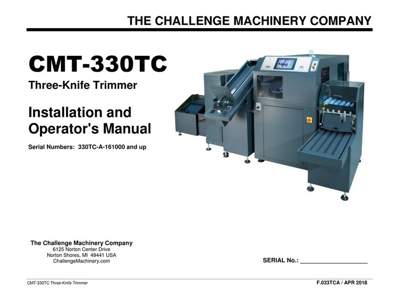
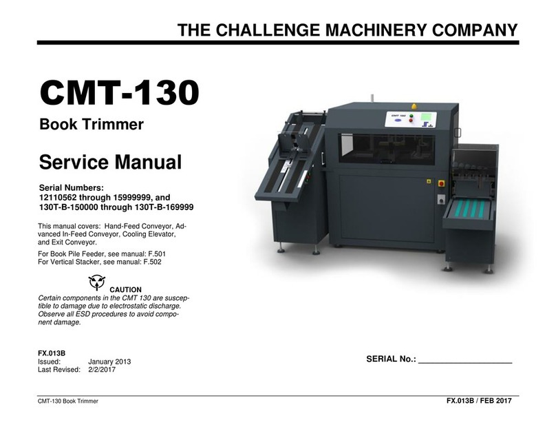
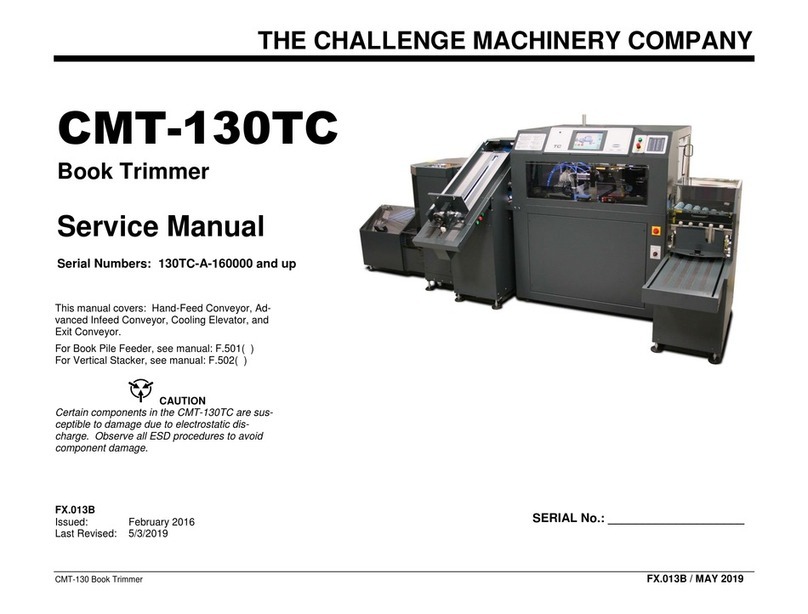
Challenge CMT-330TC User manual

THE CHALLENGE MACHINERY COMPANY
CMT-330 Three-Knife Trimmer FX.033TCA / DEC 2019
CAUTION
Certain components in the CMT-330TC are sus-
ceptible to damage due to electrostatic dis-
charge. Observe all ESD procedures to avoid
component damage.
FX.033TCA
Issued: July 2017
Last Revised: 12/16/2019
SERIAL No.: ____________________
CMT-330TC
Three-Knife Trimmer
Service Manual
Serial Numbers: 330TC-A-161000 and up

DEC 2019
Introduction ii CMT-330TC Three-Knife Trimmer
NOTICE
Service documentation is supplied to Challenge
external customers for informational purposes
only. Service documentation is intended for use
by certified, product-trained personnel only.
Challenge does not warrant or represent that
such documentation is complete, nor does Chal-
lenge represent or warrant that it will notify or
provide to such customer any future changes to
this documentation. Customer performed ser-
vice of equipment may affect the warranty of-
fered by Challenge with respect to such equip-
ment. If the customer services this equipment,
modules, components or parts thereof, the cus-
tomer releases Challenge from any and all liabil-
ity for the customer actions, and the customer
agrees to indemnify, defend and hold Challenge
harmless from any third party claims which arise
directly or indirectly from such service.
Prepared by:
The Challenge Machinery Company
6125 Norton Center Drive
Norton Shores, MI 49441 USA
Phone: 231.799.8484 Fax: 231.798.1275
ChallengeMachinery.com
©2019 by The Challenge Machinery Company.
All rights reserved.
Challenge® is a registered trademark of The
Challenge Machinery Company.
Introduction
The Challenge Machinery Company provides owner's manuals on its
products solely as a courtesy to its customers. See the information
below before using this manual.
These manuals are for reference only. These manuals include products which are noncurrent,
unsupported or no longer produced by The Challenge Machinery Company, and are provided
solely as an accommodation to our customers. By providing these manuals, The Challenge Ma-
chinery Company makes no representation or warranty as to the products, their current condition,
or their suitability or fitness for use in any particular application, which are the sole and independ-
ent responsibility of the product owner and user.
Older products may not comply with current safety procedures, guidelines or regulations,
and it is the product owner's and user's responsibility to evaluate the suitability and fitness
of the products in their current use and application. The Challenge Machinery Company
makes no representation, warranty or recommendation regarding any modifications which
may be required on non-current or unsupported products. The Challenge Machinery Com-
pany assumes no liability for any modification or alteration to any Challenge product, and
any such modification or alteration to any Challenge product is not authorized by The
Challenge Machinery Company. The availability of these manuals is solely for the purpose of
providing reference information for the products.
This manual may not be complete in all aspects of product maintenance and repair. All products
should be used only by qualified and properly trained personnel, following proper safety
procedures. All products should be regularly inspected and maintained, and their condition, ap-
plication and use should be periodically evaluated by qualified personnel. Only qualified and
properly trained technicians should perform maintenance, repair and replacement procedures.
Attempting these procedures without proper training may cause machine damage or operator
injury!
Products may be unsupported by The Challenge Machinery Company due to age or the unavail-
ability of parts from their original manufacturer. No parts or product support will be available to
repair or maintain unsupported products. Older products maynot be UL listed (if the product does
not have a UL label it is not a listed product), and may not comply with applicable installation or
other regulations or requirements if relocated to a new facility. Many municipalities require a prod-
uct to be UL listed before an electrician will connect power to them. Often the cost of updating an
older product to comply with current safety regulations is greater than the value of the product.

DEC 2019
CMT-330TC Three-Knife Trimmer iii Introduction
SAFETY
Before installing or operating any equipment, it
is important to take precautions. Read and thor-
oughly understand the safety precautions out-
lined below.
This machine is designed for one-per-
son operation. Never operate the ma-
chine with more than one person.
Safe use of this machine is the respon-
sibility of the operator. Use good judg-
ment and common sense when working
with and around the machine and its ac-
cessories.
Read and understand all instructions
thoroughly before using the machine. If
questions remain, contact your Author-
ized Challenge Dealer. Failure to un-
derstand the operating instructions may
result in personal injury.
Only trained and authorized individuals
should operate this machine.
Only trained and authorized service
technicians should service this machine.
Do not alter safety guards or devices.
They are there for your protection. Se-
vere laceration or dismemberment may
result if safety devices are altered.
Disconnect power and lock out before
performing any maintenance. See
Power Lockout Procedure on page ix.
Observe all caution and instruction la-
bels on this machine.
Be extremely careful when handling and
changing knives. Severe lacerations or
dismemberment could result from care-
less handling procedures.
Perform the Safety System Check found
in the CMT-330TC Operator’s Manual
before each shift begins.

DEC 2019
Introduction iv CMT-330TC Three-Knife Trimmer
Page
Rev.
Page
Rev.
Revision Control List
Page
Rev.
Page
Rev.
Page
Rev.
Page
Rev.

DEC 2019
CMT-330TC Three-Knife Trimmer v Introduction
Table of Contents
Introduction......................................................ii
NOTICE...................................................................ii
SAFETY .................................................................iii
Revision Control List ..............................................iv
Table of Contents....................................................v
About this Manual................................................. viii
Organization......................................................... viii
Symbology and Nomenclature ............................. viii
Power Lockout Procedure......................................ix
1. Service Call Procedures ..........................1-1
Contents.............................................................. 1-1
SCP 1.1 Initial Actions......................................... 1-1
SCP 1.2 Fault Analysis........................................ 1-1
SCP 1.3 Regular Maintenance............................ 1-1
SCP 1.4 Final Actions ......................................... 1-2
2. Status Indicator RAPs..............................2-1
Contents.............................................................. 2-1
Introduction.......................................................... 2-2
RAP 2.1 Fault Entry............................................. 2-3
RAP 2.2 Error Messages..................................... 2-4
RAP 2.3 Faults Without an Error Message.......... 2-8
RAP 2.4 Input Power......................................... 2-11
RAP 2.5 DC Power............................................ 2-13
RAP 2.6 Touch Screen Display......................... 2-15
RAP 2.7 LED Enclosure Lights.......................... 2-16
RAP 2.8 Cooling Fans....................................... 2-17
RAP 2.9 Status Light......................................... 2-18
RAP 2.10 Door Interlocks –Trimmer................. 2-19
RAP 2.11 Interlock Test..................................... 2-20
RAP 2.12 Interlock Relay .................................. 2-21
RAP 2.13 Start/Remote Cut Buttons ................. 2-22
RAP 2.14 E-Stop/Remote E-Stop Buttons......... 2-23
RAP 2.15 Starter Circuit.................................... 2-24
RAP 2.16 Hydraulic Motor Relay....................... 2-25
RAP 2.17 Hydraulic Unload and Flow Valves.... 2-26
RAP 2.18 Cut Valves......................................... 2-27
RAP 2.19 Shutdown Relay................................ 2-28
RAP 2.20 Pneumatic Pressure.......................... 2-29
RAP 2.21 Left Jogger Cylinder.......................... 2-30
RAP 2.22 Gripper Clamp Cylinder..................... 2-31
RAP 2.23 Side Knife Lock Cylinders................. 2-32
RAP 2.24 Center Clamp Cylinder......................2-33
RAP 2.25 Gripper Lift Cylinder ..........................2-34
RAP 2.26 Cover/Scrap Blast .............................2-35
RAP 2.27 Knife Latch Cylinders ........................2-36
RAP 2.28 Knife Scrap Blast...............................2-37
RAP 2.29 Registration Plate Extend Cylinder....2-38
RAP 2.30 Book Lift Air Blast..............................2-39
RAP 2.31 Book Gate Cylinder...........................2-40
RAP 2.32 Face Jog Cylinder .............................2-41
RAP 2.33 Internal Conveyor Motors..................2-42
RAP 2.34 Registration Assembly Motor ............2-43
RAP 2.35 Gripper Transport Servo Motor .........2-44
RAP 2.36 Side Knife Position Servo Motor........2-45
RAP 2.37 Knife Latch Sensors..........................2-46
RAP 2.38 Book in Gripper Sensor.....................2-47
RAP 2.39 Left Jogger Retract Sensor ...............2-48
RAP 2.40 Registration Preset Sensor ...............2-49
RAP 2.41 Side Knife Preset Sensor..................2-50
RAP 2.42 Side Knife Overtravel Switch.............2-51
RAP 2.43 Face Jog Sensor...............................2-52
RAP 2.44 Gripper Position Sensor....................2-53
RAP 2.45 Center Clamp Sensor........................2-54
RAP 2.46 Waste Bin Full Sensors.....................2-55
RAP 2.47 Knife Up Sensors ..............................2-56
RAP 2.48 Knife Slow-Down Sensors.................2-57
RAP 2.49 Knife Down Switches.........................2-58
RAP 2.50 Book Entering CMT Sensor...............2-60
RAP 2.51 Book Width Sensor............................2-61
RAP 2.52 Book Thickness Sensor.....................2-62
RAP 2.53 Barcode Scanner...............................2-63
RAP 2.54 Elevator Input Power.........................2-64
RAP 2.55 Elevator Door Interlocks....................2-65
RAP 2.56 Elevator Tilt Table Cylinders .............2-66
RAP 2.57 Elevator Tilt Infeed Motors ................2-67
RAP 2.58 Elevator Lift Motor.............................2-68
RAP 2.59 Elevator Pusher Cylinder...................2-69
RAP 2.60 Book In From Binder Sensor.............2-70
RAP 2.61 Tilt Conv. Tilt Up Switch....................2-71
RAP 2.62 Tilt Conv. Book on Tilt Sensors.........2-72
RAP 2.63 Book Entering Elevator Sensor.........2-73
RAP 2.64 Elevator Book at Top Sensor ............2-74
RAP 2.65 Elevator Shelf Level Detect Sensor...2-75
RAP 2.66 Elevator Empty Sensor......................2-76
RAP 2.67 Elevator Pusher Home Sensor..........2-77
RAP 2.68 Elevator Pusher Interlock ..................2-78
RAP 2.69 Pile Feeder Input Power....................2-79
RAP 2.70 Pile Feeder Transition Conv. Cyl.......2-80
RAP 2.71 Pile Feeder Tilt Table Cylinders ........2-81
RAP 2.72 Pile Feeder Conveyor Motors............2-82
RAP 2.73 Pile Feeder Motor Dir. Relay.............2-83
RAP 2.74 Pile Feeder Lift Servo Motor..............2-84
RAP 2.75 Pile Feeder Bottom Limit Sensor.......2-85
RAP 2.76 Pile Feeder Top Limit Sensor............2-86
RAP 2.77 Pile Feeder Book at Drop Sensor......2-87
RAP 2.78 Pile Feeder Transition Sensor...........2-88
RAP 2.79 Pile Feeder Book on Tilt Sensors......2-89
RAP 2.80 Pile Feeder Tilt Down Sensor............2-90
RAP 2.81 Stacker Input Power..........................2-91
RAP 2.82 Stacker Door Interlock.......................2-92
RAP 2.83 Stacker Roller Motor..........................2-93
RAP 2.84 Stacker Tray Up/Down Cylinder........2-94
RAP 2.85 Stacker Tray Dump Cylinder .............2-95
RAP 2.86 Stacker Pusher Cylinder....................2-96
RAP 2.87 Stacker Finger Lift Cylinder...............2-97
RAP 2.88 Stacker Roller Start Sensor...............2-98
RAP 2.89 Stacker Book In Tray Sensor.............2-99
RAP 2.90 Stacker Book to Pusher Sensor ......2-100
RAP 2.91 Stacker Pusher Cylinder Sensor .....2-101
RAP 2.92 Stacker Tray Full Sensor.................2-102
RAP 2.93 Exit Conveyor Motor........................2-103
RAP 2.94 Exit Conveyor Full Sensor...............2-104
RAP 2.95 Final Actions/System Checks..........2-105
3. Book Quality..............................................3-1
Contents..............................................................3-1
Introduction..........................................................3-1
BQ 3.1 Book Quality Entry Rap ...........................3-2
BQ 3.7 Wrinkles in Spine.....................................3-2
BQ 3.10 Books Not Accurately Trimmed .............3-2
BQ 3.2 Burr Marks...............................................3-3
BQ 3.3 Jagged Bottom Cover..............................3-3
BQ 3.4 Burr Marks/Jagged Cover........................3-3
BQ 3.5 Rectangular Crease Lines.......................3-4
BQ 3.6 Linear Crease Lines ................................3-4
BQ 3.7 Wrinkles in Spine.....................................3-4
BQ 3.8 Draw........................................................3-5
Title Page Title Page Title Page

DEC 2019
Introduction vi CMT-330TC Three-Knife Trimmer
BQ 3.9 All Sheets Not Cut................................... 3-5
BQ 3.10 Books Not Accurately Trimmed............. 3-5
BQ 3.11 Books Not Square................................. 3-6
4. Repair/Adjustment Procedures...............4-1
Contents.............................................................. 4-1
Introduction.......................................................... 4-1
REP 4.1 Cut Plates Replacement ....................... 4-2
REP 4.2 Cut Stick Replacement.......................... 4-3
REP 4.3 Knife Replacement................................ 4-4
ADJ 4.4 Knife Depth Adjustment......................... 4-8
ADJ 4.5 Lubrication............................................. 4-9
ADJ 4.6 Accuracy Adjustment........................... 4-11
ADJ 4.7 Squaring Adjustment ........................... 4-12
ADJ 4.8 Knife Down Switches Adjustment........ 4-14
ADJ 4.9 Knife Slow-Down Sensors Adjustment 4-16
ADJ 4.10 Sensor Adjustments........................... 4-17
ADJ 4.11 Timing and Conv. Belt Check/Repl.... 4-18
ADJ 4.12 Conveyor Belt Tracking Adjustment... 4-20
REP 4.13 Slide Tape......................................... 4-21
REP 4.14 Oil / Filter Change............................. 4-22
REP 4.15 Air Filter Change............................... 4-23
ADJ 4.16 Hydraulic System Pressure ............... 4-24
ADJ 4.17 Counterbalance Valves...................... 4-25
ADJ 4.18 Knife Cushion Adjustment ................. 4-26
ADJ 4.19 Book Underside Air Lift...................... 4-27
ADJ 4.20 Knife Gib Adjustment......................... 4-28
ADJ 4.21 Knife Latches..................................... 4-29
ADJ 4.22 Clamp Pressure Adjust. (Optional) .... 4-30
ADJ 4.23 Left Jog Pressure Adjustment............ 4-31
ADJ 4.24 Gripper Clamp Pressure.................... 4-32
ADJ 4.25 Face Jog Pressure............................. 4-33
ADJ 4.26 Pile Feeder Pressure......................... 4-34
ADJ 4.27 Face Jog Compensation Adjustment. 4-35
ADJ 4.28 Input Offset Adjustment..................... 4-36
ADJ 4.29 Spine Offset Adjustment.................... 4-37
REP 4.30 Main PCB Replacement.................... 4-38
REP 4.31 Console PCB Replacement .............. 4-39
REP 4.32 DI/HS PCB Replacement.................. 4-40
REP 4.33 Accessory PCB Replacement........... 4-41
ADJ 4.34 Elevator Pusher Height...................... 4-42
ADJ 4.35 Elevator Shelf Synchronization.......... 4-43
5. Parts List ...................................................5-1
Contents.............................................................. 5-1
Introduction.......................................................... 5-1
PL 5.1 Main Assembly 56000TCA (1/26) ............ 5-2
PL 5.2 Main Assembly 56000TCA (2/26) ............ 5-3
PL 5.3 Main Assembly 56000TCA (3/26) ............5-4
PL 5.4 Main Assembly 56000TCA (4/26) ............5-5
PL 5.5 Main Assembly 56000TCA (5/26) ............5-6
PL 5.6 Main Assembly 56000TCA (6/26) ............ 5-7
PL 5.7 Main Assembly 56000TCA (7/26) ............5-8
PL 5.8 Main Assembly 56000TCA (8/26) ............5-9
PL 5.9 Main Assembly 56000TCA (9/26) .......... 5-10
PL 5.10 Main Assembly 56000TCA (10/26) ......5-11
PL 5.11 Main Assembly 56000TCA (11/26) ......5-12
PL 5.12 Main Assembly 56000TCA (12/26) ......5-13
PL 5.13 Main Assembly 56000TCA (13/26) ......5-14
PL 5.14 Main Assembly 56000TCA (14/26) ......5-15
PL 5.15 Main Assembly 56000TCA (15/26) ......5-16
PL 5.16 Main Assembly 56000TCA (16/26) ......5-17
PL 5.17 Main Assembly 56000TCA (17/26) ......5-18
PL 5.18 Main Assembly 56000TCA (18/26) ......5-19
PL 5.19 Main Assembly 56000TCA (19/26) ......5-20
PL 5.20 Main Assembly 56000TCA (20/26) ......5-21
PL 5.21 Main Assembly 56000TCA (21/26) ......5-22
PL 5.22 Main Assembly 56000TCA (22/26) ......5-23
PL 5.23 Main Assembly 56000TCA (23/26) ......5-24
PL 5.24 Main Assembly 56000TCA (24/26) ......5-25
PL 5.25 Main Assembly 56000TCA (25/26) ......5-26
PL 5.26 Main Assembly 56000TCA (26/26) ......5-27
PL 5.27 Registration Asm. 56316......................5-28
PL 5.28 Power Panel EE-3554 (1/2)..................5-29
PL 5.29 Power Panel EE-3554 (2/2)..................5-30
PL 5.30 Control Console EE-3456-5 .................5-31
PL 5.31 Panel Assembly EE-3471.....................5-32
PL 5.32 Pneu. Diag. 56000TCA-P (1/4) ............5-33
PL 5.33 Pneu. Diag. 56000TCA-P (2/4) ............5-34
PL 5.34 Pneu. Diag. 56000TCA-P (3/4) ............5-35
PL 5.35 Pneu. Diag. 56000TCA-P (4/4) ............5-36
PL 5.36 Pneu. Manifold Asm. 56010-2.............. 5-37
PL 5.37 Hydraulic Power Unit –60Hz 56700 ....5-38
PL 5.38 Hydraulic Power Unit –50Hz 56700-1.5-39
PL 5.39 Manifold Assembly 56702....................5-40
PL 5.40 Hydraulic Schem. 56700-S...................5-41
PL 5.41 Manifold Sub-Plate H-517....................5-42
PL 5.42 Elevator 56431TCLA (1/7)....................5-43
PL 5.43 Elevator 56431TCLA (2/7)....................5-44
PL 5.44 Elevator 56431TCLA (3/7)....................5-45
PL 5.45 Elevator 56431TCLA (4/7)....................5-46
PL 5.46 Elevator 56431TCLA (5/7)....................5-47
PL 5.47 Elevator 56431TCLA (6/7)....................5-48
PL 5.48 Elevator 56431TCLA (7/7)....................5-49
PL 5.49 Idler 56446...........................................5-50
PL 5.50 Elev. Electrical Panel EE-3523.............5-51
PL 5.51 Elev. Pneumatics 56421TCA-P............5-52
PL 5.52 Tilt Conveyor 56630TCLA (1/8)............5-53
PL 5.53 Tilt Conveyor 56630TCLA (2/8)............5-54
PL 5.54 Tilt Conveyor 56630TCLA (3/8)............5-55
PL 5.55 Tilt Conveyor 56630TCLA (4/8)............5-56
PL 5.56 Tilt Conveyor 56630TCLA (5/8)............5-57
PL 5.57 Tilt Conveyor 56630TCLA (6/8)............5-58
PL 5.58 Tilt Conveyor 56630TCLA (7/8)............5-59
PL 5.59 Tilt Conveyor 56630TCLA (8/8)............5-60
PL 5.60 Tilt Conv. Elec. Panel EE-3547............5-61
PL 5.61 Tilt Conv. Pneumatics 56600TCA-P.....5-62
PL 5.62 Pile Feeder 58600TCLA (1/9)...............5-63
PL 5.63 Pile Feeder 58600TCLA (2/9)...............5-64
PL 5.64 Pile Feeder 58600TCLA (3/9)...............5-65
PL 5.65 Pile Feeder 58600TCLA (4/9)...............5-66
PL 5.66 Pile Feeder 58600TCLA (5/9)...............5-67
PL 5.67 Pile Feeder 58600TCLA (6/9)...............5-68
PL 5.68 Pile Feeder 58600TCLA (7/9)...............5-69
PL 5.69 Pile Feeder 58600TCLA (8/9)...............5-70
PL 5.70 Pile Feeder 58600TCLA (9/9)...............5-71
PL 5.71 Pile Feeder Electrical Panel EE-3515 ..5-72
PL 5.72 Pile Feeder Pneumatics 58500TCA-P..5-73
PL 5.73 Long Hand-Feed 56433TCLA (1/3)......5-74
PL 5.74 Long Hand-Feed 56433TCLA (2/3)......5-75
PL 5.75 Long Hand-Feed 56433TCLA (3/3)......5-76
PL 5.76 Long Hand-Feed Elec. EE-2985-1 .......5-77
PL 5.77 Std. Hand-Feed Conv. 59230TCLA......5-78
PL 5.78 Std. Hand-Feed Elec. EE-3342............5-79
PL 5.79 Outfeed Stacker 58100TCLA (1/9).......5-80
PL 5.80 Outfeed Stacker 58100TCLA (2/9).......5-81
PL 5.81 Outfeed Stacker 58100TCLA (3/9).......5-82
PL 5.82 Outfeed Stacker 58100TCLA (4/9).......5-83
PL 5.83 Outfeed Stacker 58100TCLA (5/9).......5-84
PL 5.84 Outfeed Stacker 58100TCLA (6/9).......5-85
PL 5.85 Outfeed Stacker 58100TCLA (7/9).......5-86
PL 5.86 Outfeed Stacker 58100TCLA (8/9).......5-87
PL 5.87 Outfeed Stacker 58100TCLA (9/9).......5-88
PL 5.88 Stacker Elec. Panel EE-3518...............5-89
PL 5.89 Stacker Pneumatics 58000TCA-P........5-90
PL 5.90 Stacker Air Manifold 58008 ..................5-91
PL 5.91 Exit Conv. 56430TCLA (1/3).................5-92
PL 5.92 Exit Conv. 56430TCLA (2/3).................5-93
PL 5.93 Exit Conv. 56430TCLA (3/3).................5-94
PL 5.94 Exit Conv. Elec. Panel EE-3566...........5-95
PL 5.95 Conveyor Drive Asm. 56340-1 .............5-96
PL 5.96 Conveyor Drive Asm. 56340-2 .............5-97
6. General Procedures/Information.............6-1

DEC 2019
CMT-330TC Three-Knife Trimmer vii Introduction
Contents.............................................................. 6-1
Introduction.......................................................... 6-1
GP 6.1 Retrieve Recent Error Messages ............ 6-2
GP 6.2 Input/Output Diagnostics......................... 6-3
GP 6.3 Input/Output LEDs................................... 6-4
GP 6.4 Updating Machine Software .................... 6-5
GP 6.5 Proximity Sensors ................................... 6-6
GP 6.6 Retro-reflective Sensors.......................... 6-7
GP 6.7 Diffuse Sensors....................................... 6-8
GP 6.8 Optical Distance Sensor.......................... 6-9
GP 6.9 Barcode Scanner................................... 6-10
GP 6.10 Micro-Switches.................................... 6-11
GP 6.11 Keyed Interlock Switches.................... 6-12
GP 6.12 Hirschmann Connectors...................... 6-13
GP 6.13 Contact Blocks .................................... 6-14
GP 6.14 Speed-Control Air Valves.................... 6-15
GP 6.15 Principles of Operation........................ 6-16
GP 6.16 Specifications...................................... 6-19
GP 6.17 Book Size Chart .................................. 6-20
GP 6.18 Scheduled Maintenance...................... 6-21
GP 6.19 Change Tags....................................... 6-22
7. Wiring Data................................................7-1
Contents.............................................................. 7-1
Introduction.......................................................... 7-1
WD 7.1 Trimmer Schematic –Incoming Voltage. 7-2
WD 7.2 Trimmer Schematic –120 VAC.............. 7-3
WD 7.3 Trimmer Schematic –53 VAC................ 7-4
WD 7.4 Trimmer Schematic –19 VAC................ 7-5
WD 7.5 Trimmer Schematic –9 VAC.................. 7-6
WD 7.6 Trimmer Schematic –75 VDC................ 7-7
WD 7.7 Trimmer Schematic –24 VDC................ 7-8
WD 7.8 Trimmer Schematic –15 VDC................ 7-9
WD 7.9 Trimmer Schematic –5 VDC................ 7-10
WD 7.10 Elevator Schematic –120VAC ........... 7-11
WD 7.11 Elevator Schematic –24VDC............. 7-12
WD 7.12 Tilt Schematic –120VAC.................... 7-13
WD 7.13 Tilt Schematic –24VDC ..................... 7-14
WD 7.14 Pile Feeder Schematic –120VAC...... 7-15
WD 7.15 Pile Feeder Schematic –24VDC........ 7-16
WD 7.16 Long Infeed Schematic –120VAC...... 7-17
WD 7.17 Std. Infeed Schematic –120VAC....... 7-18
WD 7.18 Stacker Schematic –120VAC ............ 7-19
WD 7.19 Stacker Schematic –24VDC.............. 7-20
WD 7.20 Exit Conv. Schematic –120VAC........ 7-21
WD 7.21 Exit Conv. Schematic –24VDC.......... 7-22
WD 7.22 Exit Conv. Schematic –5VDC............ 7-23
WD 7.23 Interconnection Diagram .................... 7-24
WD 7.24 Fuse/Circuit Breaker Chart .................7-25
8. Installation.................................................8-1
Contents..............................................................8-1
Introduction..........................................................8-1
8.1 Shipping Claims.............................................8-2
8.2 Unpacking......................................................8-2
8.3 Moving...........................................................8-2
8.4 Infeed Setup..................................................8-3
8.5 Trimmer Height Setup .................................8-12
8.6 Outfeed Setup .............................................8-13
8.7 Main Power Hookup ....................................8-17
8.8 Main Air Hookup..........................................8-19
8.9 Cleaning ......................................................8-20

DEC 2019
Introduction viii CMT-330TC Three-Knife Trimmer
About this Manual
This Service Manual is part of a multinational
documentation system that includes service
training. It is intended to supplement service
training with specific procedures and necessary
reference information to efficiently service the
CMT-330TC Three-knife trimmer.
Organization
This manual is divided into 7 sections. The sec-
tions are outlined below:
Section 1 –Service Call Procedures
This section outlines the strategy for success-
fully completing a service call.
This section includes the following:
Initial Actions
Fault Analysis
Scheduled Maintenance
Final Actions
Section 2 –Status Indicator RAPs
This section contains Repair Analysis Proce-
dures (RAPs) necessary to repair faults. Enu-
merated procedures are prefixed with RAP 2.x.
The "2" refers to section number in this manual.
Section 3 –Book Quality
This section contains procedures necessary to
correct book trim quality issues. Enumerated
procedures are prefixed with the letters BQ 3.x.
The "3" refers to the section number in this man-
ual.
Section 4 –Repairs/Adjustments
This section contains detailed procedures for the
repair and/or adjustment of mechanical and
electrical components. Enumerated procedures
are prefixed with the letters ADJ 4.x or REP 4.x.
The "4" refers to section number in this manual.
Section 5 –Parts List
This section contains exploded view drawings
and parts lists essential to the repair of the ma-
chine. Enumerated drawings are prefixed with
the letters PL 5.x. The "5" refers to its section
number in this manual.
Section 6 –General Procedures/Information
This section contains general procedures, diag-
nostic information, product specifications, tag
modification information, and other general infor-
mation. General procedures are prefixed with
the letters GP 6.x. The "6" refers to its section
number in this manual.
Section 7 –Wiring Data
This section contains Block Schematic Drawings
(BSDs) and wiring diagrams. Diagrams are enu-
merated with the prefix WD 7.x.
Section 8 –Installation Instructions
This section contains procedures necessary to
install the CMT-330TC and its accessories.
Symbology and Nomenclature
The following reference symbols are used
throughout the documentation
Warnings, Cautions, and Notes
The formats of three specific types of notes
found throughout this manual indicate the level
of danger or importance associated with the task
presented. The format of warning notes, caution
notes, and regular notes imply a certain level of
danger. The following examples give a descrip-
tion. Associate the text format and symbol with
its level of danger or importance.
Warning Definition:
WARNING
A warning indicates an operating or mainte-
nance procedure that if not observed, could
result in injury or loss of life.
Caution Definition:
CAUTION
A Caution with this symbol indicates an operat-
ing or maintenance procedure that if not ob-
served, could result in damage to equipment.
ESD Caution Definition:
CAUTION
A Caution with this symbol indicates an operat-
ing or maintenance procedure that if not ob-
served, could result in damage due to electro-
static discharge.
Note Definition:
Note: A regular note indicates an operating,
maintenance procedure that can be helpful, yet
is not required.

DEC 2019
CMT-330TC Three-Knife Trimmer ix Introduction
Warning Label Symbols
Warning labels are posted throughout the ma-
chine to indicate areas where physical injury
may occur. The following symbols are used:
Read the instruction manual.
The instruction manual should be
read and understood before operat-
ing this machine.
Do not operate with more than
one person!
One person only should operate
this machine at a time.
Cut / Crush Hazard!
Do not operate with covers re-
moved.
Do not disable safety devices.
Crush Hazard!
Do not operate with covers re-
moved.
Do not disable safety devices.
Crush / Entanglement Hazard!
Do not operate with covers or
guards removed.
Electrical Shock Hazard!
Disconnect power before removing
cover.
Electrical Shock Hazard!
Disconnect power before removing
cover.
Power Lockout Procedure
For maximum safety while making ADJUST-
MENTS or REPAIRS to your machine, lock out
the main power disconnect switch. The switch
should be moved to the OFF position and a pad-
lock securely fastened through the loop. The
person adjusting or servicing the machine
should hold the key.
Power Switch
Main Power Disconnect

DEC 2019
Introduction x CMT-330TC Three-Knife Trimmer
NOTES

DEC 2019
CMT-330TC Three-Knife Trimmer 1-1 1. Service Call Procedures
Contents
Title Page
SCP 1.1 Initial Actions......................................... 1-1
SCP 1.2 Fault Analysis........................................ 1-1
SCP 1.3 Regular Maintenance............................ 1-1
SCP 1.4 Final Actions ......................................... 1-2
SCP 1.1 Initial Actions
Initial Actions include collecting background in-
formation regarding the service issue and re-
trieving status messages from the machine's
memory.
Procedure
1. Take note of symptoms or error messages.
2. Ask the operator to describe or demonstrate
the problem.
3. If available, check the machine service log
book for any previous actions that may be
relevant to the call.
4. Retrieve status messages from the ma-
chine's memory (GP 6.1 Retrieve Recent Er-
ror Messages).
SCP 1.2 Fault Analysis
Fault analysis is done to identify faults and direct
the service technician to a resolution.
Procedure
1. Perform RAP 2.1 Fault Entry.
SCP 1.3 Regular Maintenance
Regular Maintenance is performed after proper
machine operation is re-established.
Procedure
1. Perform GP 6.18 Scheduled Maintenance.
1. Service Call Procedures

DEC 2019
1. Service Call Procedures 1-2 CMT-330TC Three-Knife Trimmer
SCP 1.4 Final Actions
Final Actions are taken to complete the service
call. Service log entries are made. If necessary,
tag modifications are made. The service issue is
closed.
Procedure
1. Perform RAP 2.95 Final Actions/System
Checks.

DEC 2019
2. Status Indicator RAPs 2-1 CMT-330TC Three-Knife Trimmer
Contents
RAP 2.1 Fault Entry............................................. 2-3
RAP 2.2 Error Messages..................................... 2-4
RAP 2.3 Faults Without an Error Message.......... 2-8
RAP 2.4 Input Power......................................... 2-11
RAP 2.5 DC Power............................................ 2-13
RAP 2.6 Touch Screen Display......................... 2-15
RAP 2.7 LED Enclosure Lights.......................... 2-16
RAP 2.8 Cooling Fans....................................... 2-17
RAP 2.9 Status Light......................................... 2-18
RAP 2.10 Door Interlocks –Trimmer................. 2-19
RAP 2.11 Interlock Test..................................... 2-20
RAP 2.12 Interlock Relay .................................. 2-21
RAP 2.13 Start/Remote Cut Buttons................. 2-22
RAP 2.14 E-Stop/Remote E-Stop Buttons......... 2-23
RAP 2.15 Starter Circuit.................................... 2-24
RAP 2.16 Hydraulic Motor Relay....................... 2-25
RAP 2.17 Hydraulic Unload and Flow Valves.... 2-26
RAP 2.18 Cut Valves......................................... 2-27
RAP 2.19 Shutdown Relay................................ 2-28
RAP 2.20 Pneumatic Pressure.......................... 2-29
RAP 2.21 Left Jogger Cylinder.......................... 2-30
RAP 2.22 Gripper Clamp Cylinder..................... 2-31
RAP 2.23 Side Knife Lock Cylinders................. 2-32
RAP 2.24 Center Clamp Cylinder...................... 2-33
RAP 2.25 Gripper Lift Cylinder.......................... 2-34
RAP 2.26 Cover/Scrap Blast............................. 2-35
RAP 2.27 Knife Latch Cylinders........................ 2-36
RAP 2.28 Knife Scrap Blast............................... 2-37
RAP 2.29 Registration Plate Extend Cylinder.... 2-38
RAP 2.30 Book Lift Air Blast.............................. 2-39
RAP 2.31 Book Gate Cylinder........................... 2-40
RAP 2.32 Face Jog Cylinder............................. 2-41
RAP 2.33 Internal Conveyor Motors.................. 2-42
RAP 2.34 Registration Assembly Motor ............ 2-43
RAP 2.35 Gripper Transport Servo Motor ......... 2-44
RAP 2.36 Side Knife Position Servo Motor........ 2-45
RAP 2.37 Knife Latch Sensors.......................... 2-46
RAP 2.38 Book in Gripper Sensor..................... 2-47
RAP 2.39 Left Jogger Retract Sensor ............... 2-48
RAP 2.40 Registration Preset Sensor............... 2-49
RAP 2.41 Side Knife Preset Sensor.................. 2-50
RAP 2.42 Side Knife Overtravel Switch.............2-51
RAP 2.43 Face Jog Sensor...............................2-52
RAP 2.44 Gripper Position Sensor....................2-53
RAP 2.45 Center Clamp Sensor........................2-54
RAP 2.46 Waste Bin Full Sensors.....................2-55
RAP 2.47 Knife Up Sensors ..............................2-56
RAP 2.48 Knife Slow-Down Sensors.................2-57
RAP 2.49 Knife Down Switches.........................2-58
RAP 2.50 Book Entering CMT Sensor...............2-60
RAP 2.51 Book Width Sensor............................2-61
RAP 2.52 Book Thickness Sensor.....................2-62
RAP 2.53 Barcode Scanner...............................2-63
RAP 2.54 Elevator Input Power.........................2-64
RAP 2.55 Elevator Door Interlocks....................2-65
RAP 2.56 Elevator Tilt Table Cylinders .............2-66
RAP 2.57 Elevator Tilt Infeed Motors ................2-67
RAP 2.58 Elevator Lift Motor.............................2-68
RAP 2.59 Elevator Pusher Cylinder...................2-69
RAP 2.60 Book In From Binder Sensor.............2-70
RAP 2.61 Tilt Conv. Tilt Up Switch....................2-71
RAP 2.62 Tilt Conv. Book on Tilt Sensors.........2-72
RAP 2.63 Book Entering Elevator Sensor.........2-73
RAP 2.64 Elevator Book at Top Sensor ............2-74
RAP 2.65 Elevator Shelf Level Detect Sensor...2-75
RAP 2.66 Elevator Empty Sensor......................2-76
RAP 2.67 Elevator Pusher Home Sensor..........2-77
RAP 2.68 Elevator Pusher Interlock.................. 2-78
RAP 2.69 Pile Feeder Input Power....................2-79
RAP 2.70 Pile Feeder Transition Conv. Cyl.......2-80
RAP 2.71 Pile Feeder Tilt Table Cylinders........2-81
RAP 2.72 Pile Feeder Conveyor Motors............2-82
RAP 2.73 Pile Feeder Motor Dir. Relay.............2-83
RAP 2.74 Pile Feeder Lift Servo Motor..............2-84
RAP 2.75 Pile Feeder Bottom Limit Sensor.......2-85
RAP 2.76 Pile Feeder Top Limit Sensor............2-86
RAP 2.77 Pile Feeder Book at Drop Sensor......2-87
RAP 2.78 Pile Feeder Transition Sensor...........2-88
RAP 2.79 Pile Feeder Book on Tilt Sensors......2-89
RAP 2.80 Pile Feeder Tilt Down Sensor............2-90
RAP 2.81 Stacker Input Power..........................2-91
RAP 2.82 Stacker Door Interlock.......................2-92
RAP 2.83 Stacker Roller Motor..........................2-93
RAP 2.84 Stacker Tray Up/Down Cylinder ........2-94
RAP 2.85 Stacker Tray Dump Cylinder .............2-95
RAP 2.86 Stacker Pusher Cylinder....................2-96
RAP 2.87 Stacker Finger Lift Cylinder...............2-97
RAP 2.88 Stacker Roller Start Sensor...............2-98
RAP 2.89 Stacker Book In Tray Sensor.............2-99
RAP 2.90 Stacker Book to Pusher Sensor ......2-100
RAP 2.91 Stacker Pusher Cylinder Sensor .....2-101
RAP 2.92 Stacker Tray Full Sensor.................2-102
RAP 2.93 Exit Conveyor Motor........................2-103
RAP 2.94 Exit Conveyor Full Sensor...............2-104
RAP 2.95 Final Actions/System Checks..........2-105
2. Status Indicator RAPs
Title Page Title Page Title Page

DEC 2019
2. Status Indicator RAPs 2-2 CMT-330TC Three-Knife Trimmer
Introduction
The status indicator repair analysis procedures
(RAPs) provide in-depth troubleshooting
measures. They were designed for thorough
resolution of faults indicated by status messages
or controller board states.
WARNING
HIGH VOLTAGE! Nearly all RAPs require
that the machine have power while testing.
Use extreme caution at ALL times. Serious
injury or death may result from unsafe test-
ing practices. If replacing parts, lock out
main power at the source according to the
Power Lockout Procedure on page ix.
CAUTION
Standard precautions to prevent electro-static
discharge must be taken when working with
PCBs. Observe these practices whenever work
is being done in the electrical panel.

DEC 2019
CMT-330TC Three-Knife Trimmer 2-3 2. Status Indicator RAPs
RAP 2.1 Fault Entry
This RAP should be performed on every service
call in order to correctly diagnose and trouble-
shoot the problem being reported.
Initial Actions
Clear all books from the trimmer and accesso-
ries.
Check that all doors are closed completely.
Procedure
1. Ask the customer to describe the problem.
2. Check that a compressed air line is con-
nected to the trimmer, and is suppling com-
pressed air at least 80 psi (for compressed
air requirements and hookup, see Section
8.8 Main Air Hookup).
3. Check that the main air valve at the back of
the trimmer is switched on.
4. Switch the main power ON at the power
switch shown in Figure 2-1. Does the touch
screen display come on?
Y N
Perform RAP 2.4 Input Power and RAP 2.5
DC Power to confirm that all power sources
are working properly. Perform RAP 2.6
Touch Screen Display if necessary. Does
the problem still exist?
Y N
Go to Step 13.
5. Are there any error messages on the
screen?
Y N
Go to Step 7.
6. When possible, attempt to resolve and clear
the error message (for example, for an open
door message, close the door). It may be
necessary to switch the power OFF and
back ON. If the error message continues to
display, go to RAP 2.2 Error Messages and
perform the applicable RAPs until no error
messages show at this step. Does a prob-
lem still exist?
Y N
Go to Step 13.
7. Push the green start button. Does the hy-
draulic motor start?
Y N
Perform RAP 2.15 Starter Circuit
8. Are there any error messages on the
screen?
Y N
Go to Step 10.
9. When possible, attempt to resolve and clear
the error message (for example, for an open
door message, close the door). It may be
necessary to switch the power OFF and
back ON. If the error message continues to
display, go to RAP 2.2 Error Messages and
perform the applicable RAPs until no error
messages show at this step. Does a prob-
lem still exist?
Y N
Go to Step 13.
10. Do the gripper and other mechanical compo-
nents initialize properly?
Y N
Perform RAP 2.4 Input Power and RAP 2.5
DC Power to confirm that all power sources
are working properly. If the gripper does not
move, go to RAP 2.35 Gripper Transport
Servo Motor.
11. Is the problem a book quality problem?
Y N
Go to RAP 2.3 Faults Without an Error Mes-
sage and perform the applicable RAPs.
When complete, go to Step 13.
12. Go to BQ 3.1 Book Quality Entry Rap. When
complete, go to Step 13.
13. Go to GP 6.18 Scheduled Maintenance and
perform any necessary routine maintenance.
14. Perform RAP 2.95 Final Actions/System
Checks.
Figure 2-1. Start Up Controls

DEC 2019
2. Status Indicator RAPs 2-4 CMT-330TC Three-Knife Trimmer
RAP 2.2 Error Messages
An error message will appear on the display
screen often times when there is a fault. The fol-
lowing table contains the complete list of possi-
ble error messages. Always attempt to resolve
and clear the error message before performing
the recommended procedures in this list (for ex-
ample, for an open door message, close the
door). It may be necessary to switch the power
OFF and back ON in order to clear the mes-
sage. If the error message cannot be resolved
or continues to be displayed, follow the associ-
ated recommended procedures shown below.
Error Messages (in Alphabetical Order)
Recommended Procedures
Accuracy is out of range
ADJ 4.6 Accuracy Adjustment
Bar Code Error
RAP 2.53 Barcode Scanner
Book did not reach Width sensor in time
RAP 2.51 Book Width Sensor
Book failed to clear Book in Gripper Sensor
RAP 2.38 Book in Gripper Sensor
Book finish length outside limits
See Installation and Operator's Manual for allowed dimensions
Book finish width outside limits
See Installation and Operator's Manual for allowed dimensions
Book in Elevator JAM Error
RAP 2.63 Book Entering Elevator Sensor
RAP 2.57 Elevator Tilt Infeed Motors
RAP 2.58 Elevator Lift Motor
Book Length & Trim combination too large
See Installation and Operator's Manual for allowed dimensions
Book Start length outside limits
See Installation and Operator's Manual for allowed dimensions
Book Start width outside limits
See Installation and Operator's Manual for allowed dimensions
Book Thickness Sensor OFF Unexpectedly
RAP 2.52 Book Thickness Sensor
Book Thickness Sensor ON Unexpectedly
RAP 2.50 Book Entering CMT Sensor
RAP 2.52 Book Thickness Sensor
Book Thickness value too large
See Installation and Operator's Manual for allowed dimensions
Center Clamp Error
RAP 2.24 Center Clamp Cylinder
RAP 2.45 Center Clamp Sensor
Connection Lost to I/O Motor Controller!
Switch the main power OFF and then back ON.
Check all cable connections between trimmer and accessories
RAP 2.6 Touch Screen Display

DEC 2019
CMT-330TC Three-Knife Trimmer 2-5 2. Status Indicator RAPs
Error Messages (in Alphabetical Order)
Recommended Procedures
EE memory Read Fail
GP 6.4 Updating Machine Software
REP 4.31 Console PCB Replacement
EE memory Write failed
GP 6.4 Updating Machine Software
REP 4.31 Console PCB Replacement
Elevator Book on Tilt Error
RAP 2.62 Tilt Conv. Book on Tilt Sensor
RAP 2.63 Book Entering Elevator Sensor
RAP 2.57 Elevator Tilt Infeed Motors
RAP 2.58 Elevator Lift Motor
Elevator Book Push Error
RAP 2.59 Elevator Pusher Cylinder
RAP 2.67 Elevator Pusher Home Sensor
RAP 2.68 Elevator Pusher Interlock
Elevator Door Open
RAP 2.55 Elevator Door Interlocks
Elevator Failed to Lift
RAP 2.65 Elevator Shelf Level Detect Sensor
RAP 2.58 Elevator Lift Motor
Elevator JAM Book on Top
RAP 2.64 Elevator Book at Top Sensor
Elevator JAM From the Binder
RAP 2.62 Tilt Conv. Book on Tilt Sensor
RAP 2.63 Book Entering Elevator Sensor
RAP 2.57 Elevator Tilt Infeed Motors
RAP 2.58 Elevator Lift Motor
Elevator Tilt Door Open
RAP 2.55 Elevator Door Interlocks
Elevator Tilt Error
RAP 2.62 Tilt Conv. Book on Tilt Sensors
RAP 2.61 Tilt Conv. Tilt Up Switch
RAP 2.56 Elevator Tilt Table Cylinders
RAP 2.57 Elevator Tilt Infeed Motors
Elevator Top Door Open
RAP 2.55 Elevator Door Interlocks
Face Jog Failed to Rotate
RAP 2.32 Face Jog Cylinder
RAP 2.43 Face Jog Sensor
Flash file is corrupted! CheckSum failed
GP 6.4 Updating Machine Software
Gripper not at Side Cut Position Sensor
RAP 2.44 Gripper Position Sensor
Interlock relay OFF when should be ON
RAP 2.12 Interlock Relay
RAP 2.15 Starter Circuit
JAM - Book Between Sensor Error
RAP 2.50 Book Entering CMT Sensor
RAP 2.33 Internal Conveyor Motors
Knife failed to leave down limit in time!
RAP 2.49 Knife Down Switches
RAP 2.17 Hydraulic Unload and Flow Valve
RAP 2.18 Cut Valve

DEC 2019
2. Status Indicator RAPs 2-6 CMT-330TC Three-Knife Trimmer
Error Messages (in Alphabetical Order)
Recommended Procedures
Knife failed to leave up limit in time
RAP 2.47 Knife Up Sensors
RAP 2.17 Hydraulic Unload and Flow Valve
RAP 2.18 Cut Valve
Knife failed to reach down limit in time!
RAP 2.49 Knife Down Switches
RAP 2.17 Hydraulic Unload and Flow Valve
RAP 2.18 Cut Valve
RAP 2.47 Knife Up Sensors
Knife failed to reach Slow Down Prox
RAP 2.48 Knife Slow-Down Sensors
RAP 2.49 Knife Down Switches
Knife failed to reach up Sensor (Check Mo-
tor Rotation)
Section 8.7 Main Power Hookup
RAP 2.47 Knife Up Sensors
RAP 2.17 Hydraulic Unload and Flow Valve
RAP 2.18 Cut Valve
Knife Latch did not pull in!
RAP 2.27 Knife Latch Cylinders
RAP 2.37 Knife Latch Sensors
Knife Latch OUT when should be IN
RAP 2.27 Knife Latch Cylinders
RAP 2.37 Knife Latch Sensors
Left Jog Failed to Extend
RAP 2.21 Left Jogger Cylinder
RAP 2.39 Left Jogger Retract Sensor
Linear Position Err. Press Stop, Then Green
Start
RAP 2.35 Gripper Transport Servo Motor
Lubricate Machine and Clear Lube Counter
ADJ 4.5 Lubrication
Machine Front Door Open
RAP 2.12 Interlock Relay
RAP 2.10 Door Interlocks
Machine Rear Door Open
RAP 2.12 Interlock Relay
RAP 2.10 Door Interlocks
Machine Side Door Open
RAP 2.12 Interlock Relay
RAP 2.10 Door Interlocks
Motor failed to move
RAP 2.35 Gripper Transport Servo Motor
Motor Starter off when it should be on!
RAP 2.15 Starter Circuit
RAP 2.58 Elevator Lift Motor
RAP 2.93 Exit Conveyor Motor
RAP 2.21 Left Jogger Cylinder
Motor Starter on when it should be off!
RAP 2.15 Starter Circuit
RAP 2.58 Elevator Lift Motor
RAP 2.93 Exit Conveyor Motor

DEC 2019
CMT-330TC Three-Knife Trimmer 2-7 2. Status Indicator RAPs
Error Messages (in Alphabetical Order)
Recommended Procedures
No Air Pressure!
RAP 2.20 Pneumatic Pressure
Output is Full
RAP 2.94 Exit Conveyor Full Sensor
Pile Feeder Book Not Received
RAP 2.79 Pile Feeder Book on Tilt Sensors
RAP 2.72 Pile Feeder Conveyor Motors
RAP 2.59 Elevator Pusher Cylinder
Pile Feeder Book On Tilt
RAP 2.79 Pile Feeder Book on Tilt Sensors
RAP 2.72 Pile Feeder Conveyor Motors
Pile Feeder Tilt Down Error
RAP 2.80 Pile Feeder Tilt Down Sensor
Registration Data Error
RAP 2.40 Registration Preset Sensor
RAP 2.34 Registration Assembly Motor
Registration motor failed to move
RAP 2.34 Registration Assembly Motor
Registration Position Error
RAP 2.40 Registration Preset Sensor
RAP 2.34 Registration Assembly Motor
Sharpen Knife and Clear Knife Counter
REP 4.3 Knife Replacement
To clear counter, see Installation and Operator's Manual
Side Knives failed to reach Position
RAP 2.36 Side Knife Position Servo Motor
RAP 2.41 Side Knife Preset Sensor
RAP 2.42 Side Knife Overtravel Switch
Stacker Book Jam at Input
RAP 2.88 Stacker Roller Start Sensor
RAP 2.83 Stacker Roller Motor
Stacker Book Jam Book to Pusher
RAP 2.90 Stacker Book to Pusher Sensor
RAP 2.85 Stacker Tray Dump Cylinder
Stacker Book Jam Start
RAP 2.89 Stacker Book In Tray Sensor
RAP 2.84 Stacker Tray Up/Down Cylinder
RAP 2.85 Stacker Tray Dump Cylinder
Stacker Door Open
RAP 2.82 Stacker Door Interlock
Stacker Output Full
RAP 2.92 Stacker Tray Full Sensor
Stacker Push Position Error
RAP 2.91 Stacker Pusher Cylinder Sensor
RAP 2.86 Stacker Pusher Cylinder
Stop Button is Pressed
RAP 2.14 E-Stop/Remote E-Stop Buttons
Target Position out of range
See Installation and Operator's Manual for allowed dimensions

DEC 2019
2. Status Indicator RAPs 2-8 CMT-330TC Three-Knife Trimmer
RAP 2.3 Faults Without an Error Message
Note: For book quality issues, go to BQ 3.1 Book Quality Entry Rap.
Description of Fault
Recommended Procedures
Trimmer Faults
Machine will not switch on
RAP 2.4 Input Power
The status light is always on, or never on
RAP 2.9 Status Light
Console will not illuminate
RAP 2.6 Touch Screen Display
RAP 2.4 Input Power
Enclosure lights will not switch on or will not switch off
RAP 2.7 LED Enclosure Lights
Cooling fan(s) do not function
RAP 2.8 Cooling Fans
The hydraulic motor will not start
RAP 2.4 Input Power
RAP 2.15 Starter Circuit
The internal conveyors will not start and the gripper will not
move
RAP 2.12 Interlock Relay
RAP 2.15 Starter Circuit
The internal conveyors do not run while the pump motor is
on
RAP 2.33 Internal Conveyor Motors
The internal conveyors run while the pump motor is off
RAP 2.33 Internal Conveyor Motors
Registration assembly fails to move
RAP 2.40 Registration Preset Sensor
RAP 2.34 Registration Assembly Motor
Gripper clamp will not clamp, will not un-clamp, or is other-
wise stuck
RAP 2.22 Gripper Clamp Cylinder
Gripper never clamps book and/or books are delivered to
outfeed accessory without being cut
RAP 2.38 Book in Gripper Sensor
Gripper freezes in registration area
RAP 2.32 Face Jog Cylinder
RAP 2.43 Face Jog Sensor
Registration stop plate is always extended, never extends,
or extends erratically
RAP 2.29 Registration Plate Extend Cylinder
The left side jogger fails to extend
RAP 2.21 Left Jogger Cylinder
The knife/knives will not come down
RAP 2.17 Hydraulic Unload and Flow Valve
The knife/knives stay down and hydraulic fluid passes over
the relief valve
RAP 2.17 Hydraulic Unload and Flow Valve
RAP 2.49 Knife Down Switches
Knife mechanism cuts with high impact at bottom of stroke
even when cushioning is set HIGH
RAP 2.17 Hydraulic Unload and Flow Valve
RAP 2.48 Knife Slow-Down Sensors
Other manuals for CMT-330TC
1
Table of contents
Other Challenge Trimmer manuals

Challenge
Challenge HTEG33-550 Operation instructions

Challenge
Challenge CGT180 User manual

Challenge
Challenge M0E-12ET-410 Operation instructions

Challenge
Challenge CMT-130 User manual

Challenge
Challenge M0E-9ET-410 Operation instructions

Challenge
Challenge HTEG34C-450 User manual

Challenge
Challenge DOCUTRIM Technical reference manual

Challenge
Challenge N1F-GT-250-B Operation instructions

Challenge
Challenge N0E-15ET-230 Operation instructions

Challenge
Challenge N0E-2ET-230 User manual