Challenger Smart Force ASFK1 User manual

Challenger_ASFK1_Instructions_Rev01
ASFK1
Gateway
Hub
User Manual
1. Introduction
The ASFK1 Gateway is a member of the Smart Force series and is fully
compatible with any Smart Force enabled devices. It can remotely
control and monitor remote enabled devices. Whether onsite or logged
in through the internet, you will always have access to control and
monitor your control system. With this system you can achieve a better
control of your home security to make your life safer and easier than
ever.
2. Appearance
Figure 1 ASFK1 Gateway Hub
2.1 Sockets
DC Jack: DC power voltage 9V, current 2A.
RJ-45 socket: ASFK1 has an Ethernet hub function and is equipped
with two linked RJ-45 sockets.
2.2 Buttons
ASFK1 has two buttons: One reset button and a connection button
(next to the RJ-45 socket).
■Reset Button:
This button will reboot the system. The user can press this button
when the system has stopped working.
Note: ASFK1 is equipped with internal battery power, which will be
automatically switched on when DC power is disconnected.
■Connection Button:
‧
Manually enable the learn function:
Press the connection button once after the system is powered on.
‧
Manually cancel the learn function:
Press the connection button once when the system is in learn
mode.
2.3. LED
Figure 2 ASFK1 Front View
Definition of LED:
LED1 Power LED2 Connection
LED3 Network 1
LED (RJ45) LED4 Network 2
LED (RJ45)
2.3.1 Power LED
Green light: The power is on.
Red light: Flashing writing data.
Red light flashes every 5 seconds: The system time is not
synchronized after boot up.
2.3.2. Connection LED
Green light: Open VPN has successfully connected to the server.
Red light: The DHCP function is enabled but could not obtain IP
information.
Red and green light flashes: The firmware is being upgraded.
Green light flashes every of 0.5 seconds: The system is in learning
mode.
Green light flashes every 2 seconds: The system has successfully
added other radio devices.
LED1 LED2 LED3 LED4
Challenger_ASFK1_Instructions_Rev01
Green light flashes every 0.1 seconds: If code learning has timed out
it will continue to flash for 4 seconds.
If code learning is aborted it will continue to flash for 1 second.
Green and red light flash 3 times: The system has successfully
booted up.
2.3.3 Network 1 LED
Green light: The RJ-45 socket near the connection button is
connecting.
2.3.4 Network 2 LED
Green light: The RJ-45 socket near the DC power jack is
connecting.
2.4 USB
There are three USB sockets in the box, which can plug to the 3G dongle.
3. Installation
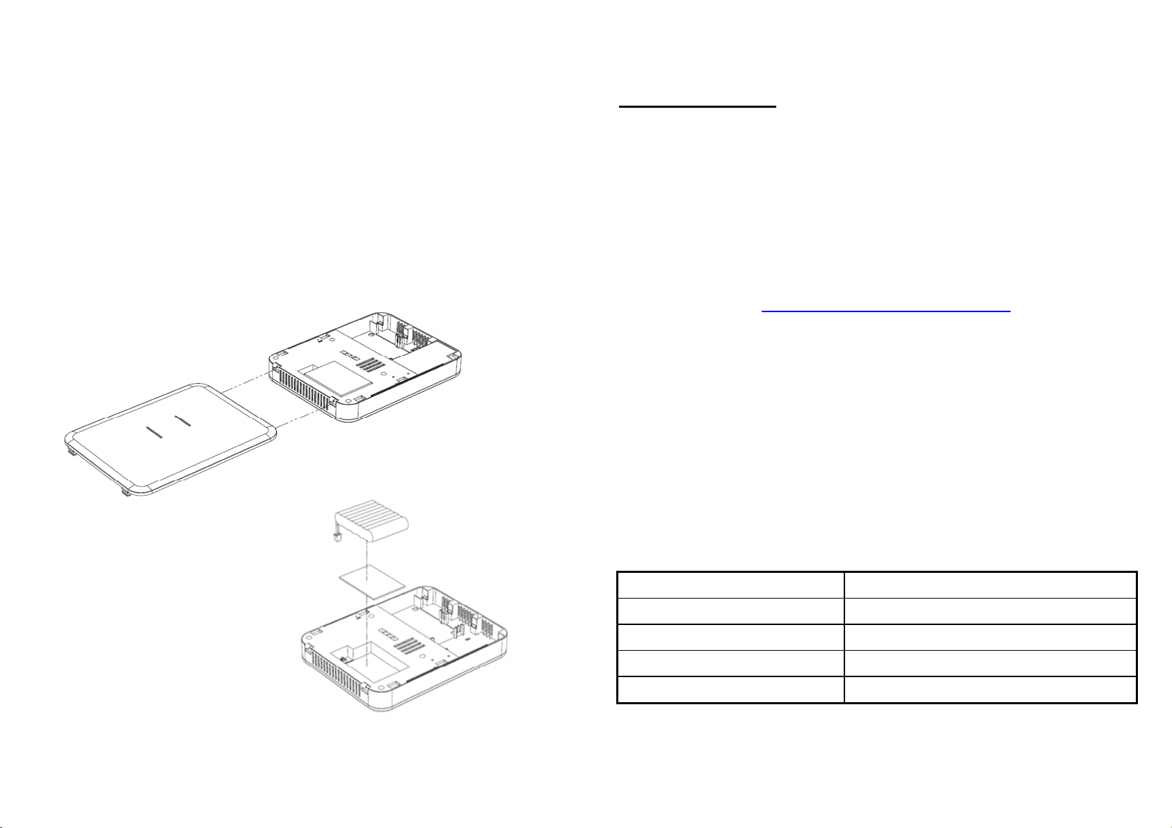
Figure 3 Upper cover installation
‧Press and hold the latch.
‧Slide to release the upper cover.
‧Fit the latch to replace the upper cover.
Figure 4 Battery installation
‧Stick the double-sided tape to where you wish to place the batteries and
mark the batteries with the installation date.
‧Attach batteries and insert power cables to complete installation.
IMPORTANT NOTE:
The devices supplied in the kit HAVE already been
learnt to the Gateway Hub and does not require learning to the ASFK1 Gateway
Hub. Please ensure if learning additional devices that are not supplied in the kit
that these are learnt before installation of the devices.
4. Learning
Learning is an operation of the ASFK1 used to include other radio
devices.
To Start Learning:
The easiest way to learn the device to the Gateway Hub is either via through
the Smart Force Web Site or Smart Force App once you have completed the
System Registration.
https://smartforce.mylu home.com/
Press the connection button once and the connection LED will flash
green.
Device Learning:
The connection LED on the ASFK1 will stop flashing and turn on and
off with an interval of 2 seconds if learning the device was successful.
Cancel Learning:
Press the connection button when the connection LED is blinking in
learning mode and the connection LED will flash rapidly and stop
learning.
Learning Timeout:
Timeout will happen when the learning mode has been idle for 30
seconds. The connection LED will rapidly flash 4 seconds when this
happens.
Specifications
Operating temperature range -10°C to +40°C
Operating humidity 5 - 85% RH
Battery type Rechargeable NiMH, 6V,2100mAH
Transmission range Indoors 30m; Outdoors >100m (Open space)
Frequency range 868.3 MHz

Challenger_ASFK1_Instructions_Rev01
Due to our policy of continuous improvement we reserve the right to change specification
without prior notice.
Errors and omissions excepted. These instructions have been carefully checked prior to
publication. However, no responsibility can be accepted by Challenger for any
misinterpretation of these instructions.
Challenger Security Products
10 Sandersons Way, Blackpool, FY4 4NB
Tel: 01253 791888, Fax: 01253 791887
Web: www.challenger.co.uk


