manuals.online logo
Brands
  1. Home
  2. •
  3. Brands
  4. •
  5. Chamberlain
  6. •
  7. Garage Door Opener
  8. •
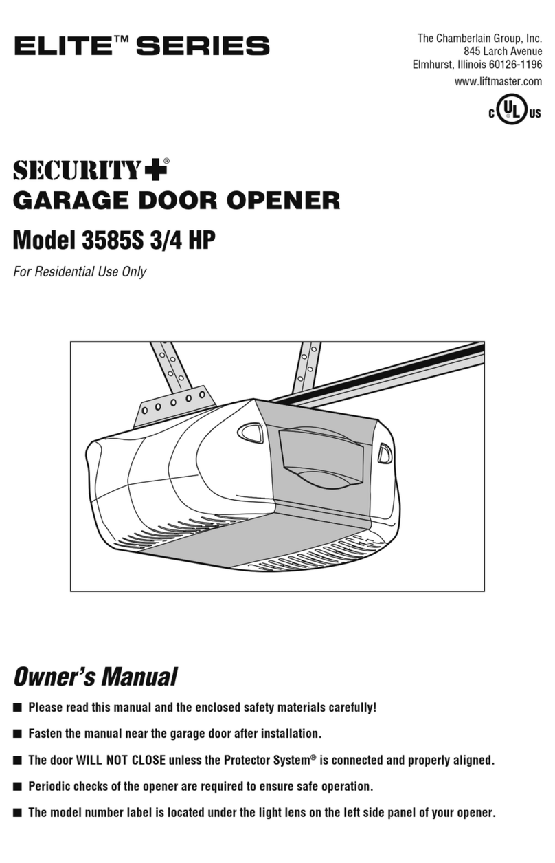
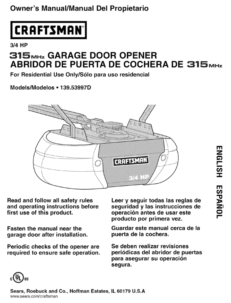
  9. Chamberlain LiftMaster SCS300K User manual

Chamberlain LiftMaster SCS300K User manual

Für Service: +49 (0)6838/907-172 Pour Service: 03-87-98-15-93
For Service: +49 (0)6838/907-172 Voor Service: 020-684-7978
DF
GB NL
SCS300K
SCS300KS
www.liftmaster.com
[email protected]
1-GB
Contents: General advice on
installation and use:
Contents list: page 1
Content of the carton: page 1, figure
Before you begin: page 2
Checklist: page 2
Gate types/installation height:
page 2, figure A-F
Gate configuration:
page 2, figure A-F
Gate stops:
page 2, figure
Post bracket/Gate fixing bracket:
pages 2-3, figures A-D
Release of drive arms:
page 3, figure
Installing the drive arms::
page 3, figure
Wiring: page 3, figure
Initial operation: page 3
Maintenance work: page 3
Technical Data: page 3
Replacement Parts: figure
Electronic control with connections:
page 4, figure
Elektrical Installation:
page 4, figure
Force adjustment: page 5
Safety: page 5, figures -
Combined Operation: page 5
Antenna: page 5, figure
Flashing Lamp: Page 5, figure
Key switch: page 5, figure
Initial setting of Remot control:
page 6, figure
Initial Operation: page 6
CE Declaration of Conformity: page 6
CONTENT OF THE CARTON
(1) Motor (1)
(2) Electronic Control (1)
(3) Postbracket (1)
(4) Keys (2)
(5) Gate fixing bracket (1)
(6) Capacitor (1)
(7) Manual (1)
(8) Clevis pin (2) and Rings (4)
(9) Nut (1 or 2)
(10) Washer (1 or 2)
(11) 3-Channel Remote Control Mini (1)
(12) IR Sensor (1 pair)
(13) Flashing lamp (1)
(14) Antenna (1)
1
PLEASE START BY READING THESE IMPORTANT SAFETY RULES • SAVE THESE INSTRUCTIONS
This safety alert symbol means "Caution" - failure to comply with such an instruction involves risk of personal
injury or damage to property. Please read these warnings carefully.
This gate drive mechanism is designed and tested to offer appropriately safe service provided it is installed and
operated in strict accordance with the following safety rules.
Incorrect installation and/or failure to comply with the following instructions may result in serious personal injury
or property damage.
1
2
3
4
5
6
77
813
Installation and wiring must be in compliance
with your local building and electrical
installation codes. Power cables must only be
connected to a properly earthed supply.
Any entrapment possibility by the moving wing
between wing & walls must be secured with
safety edges or IR-sensors.
Disconnect electric power to the system before
making repairs or removing covers.
A disconnecting device must be provided in the
permanently-wired installation to guarantee all-
pole disconnection by means of a switch (at least
3mm contact gap) or by a separate fuse.
When using tools and small parts to install or
carry out repair work on a gate exercise caution
and do not wear rings, watches or loose
clothing.
Make sure that people who install, maintain or
operate the gate drive follow these instructions.
Keep these instructions in a safe place so that you
can refer to them quickly when you need to.
Please remove any locks fitted to the gate in order
to prevent damage to the gate.
It is important to make sure that the gate always
runs smoothly. Gates which stick or jam must be
repaired immediately. Employ a qualified
technician to repair the gate, never attempt to
repair it yourself.
Keep additional accessories away from children. Do
not allow children to play with pushbuttons or remote
controls. A gate can cause serious injuries as it
closes.
After the installation a final test of the full
function of the system and the full function of
the safety devices must be done.
The full protection against potential squeeze or
entrappment must work direct when the drive
arms are installed.
This drive cannot be used with a gate
incorporating a wicket door unless the drive
cannot be operated with the wicket door open.
9
13
8
10
2-GB
GATE CONFIGURATION
How far must the gate leaf open?
90 degrees or up to 115 degrees. An opening angle in excess
of 115 degrees is possible to a limited extent but is not
recommended. Reason: the drive mechanism always runs at
the same speed. The further the gate has to be opened, the
faster the gate leaf must travel. Movement becomes more
erratic and this subjects the fittings and gate to extreme
stresses. Non-identical opening angles cause one drive
mechanism to reach its destination first, but continues to run,
thereby forcing the gate up against the gate stop until the
other motor eventually reaches its end position
(see Figures 3, A-E).
Tip for professionals: The time taken to reach the limit stop
can be controlled by deliberately selecting different A and B
dimensions (left + right). However, this method of installing
subjects the fittings to high stresses and can cause the gate
to run erratically. It is recommended that only experienced
gate installers adopt this method.
GATE STOPS
A SWING GATE NEEDS A FIXED GATE STOP IN BOTH
THE OPEN AND CLOSE DIRECTIONS. Gate stops save
wear and tear on the drive mechanism, gate and fittings.
Operating a gate without fixed limit stops results in poor
performance. It is often dangerous, leads to premature wear
and voids your warranty!
POST FIXING BRACKET
Choosing the correct location for the post fitting bracket
has a decisive impact on the subsequent functioning of
the system. It determines the distance between the motor's
centre of motion and the gate's centre of motion and hence
the opening angle. These dimensions are referred to as
dimension A and dimension B. Do not underestimate the
effect that these dimensions have on correct functioning and
running. Try and achieve the best dimension for your opening
angle, as precisely as possible and suitable for all
circumstances. See Table (Figure 3F) for dimensions A/B.
If the post is not wide enough, an extension piece must be
fitted to it (Figure 5B). If the post is too thick, cut out part of it
to make it thinner (Figure 5D) or offset the gate (Figure 5C).
To obtain ideal dimensions, it may be necessary to shorten or
lengthen the supplied hinge plate. In the case of gates that
are to be custom made, if the gate hinges are fitted on the
posts appropriately, it is possible to influence dimensions A
and B. Before the final mounting dimensions are determined,
you should always check whether or not there is any
possibility that the corner of the drive mechanism will hit the
post as the gate swings.
INSTALLATION: The drive mechanism exerts considerable
force against the post. Usually, acceptable mounting
dimensions are obtained if the supplied hinge plate is welded
directly onto the post. In the case of thick stone or concrete
posts, the hinge must be welded to a base plate and
attached so that the dowels cannot work loose during
operation. Heavy-duty dowels where a threaded rod is
bonded into the masonry stress-free are more suitable for
this purpose than steel or plastic straddling dowels. In the
case of brickwork pillars, bolt on a relatively large steel plate
that covers several bricks and then weld the hinge plate to it.
An angle plate attached over the corner of the post is also a
good means of fixing the operator.
5
4
3
BEFORE YOU BEGIN
The drive mechanism needs room to the side permitting
correct installation of drive arms. Please make sure that this
is available. Gates affected by high wind loads must also be
protected by an (electric) lock.
There are many factors to consider when choosing the right
drive mechanism. Assuming that a gate functions properly,
"startup" is the most difficult phase, once the gate is in motion,
significantly less force is usually required to move it.
• Gate size: Gate size is a very important factor. Wind can
brake or distort the gate, thereby increasing the amount of
force needed to move it considerably.
• Gate weight: The weight of the gate in not as relevant as
the size.
• Effect of temperature: Low outdoor temperatures can
make initial startup more difficult (changes in the ground,
etc.) or even prevent it. High outdoor temperatures along
with frequent use can trigger thermal protection
prematurely (approx. 135 ºC).
• Operating frequency/operating time: Drive mechanisms
are designed for a maximum operating time (running time)
of approximately 30% (e.g. 30% during any one hour).
IMPORTANT: The drive mechanism is not designed to
operate continuously at its maximum operating time (non-
stop operation). Otherwise the drive mechanism becomes
too hot and switches off until it cools down to the switch-on
temperature. The outdoor temperature and the gate are
important parameters that affect the actual operating time.
INSTALLATION CHECKLIST - PREPARATIONS
Check the carton contents and read the instructions carefully.
Make sure your gate equipment operates perfectly. The gate
must run evenly and smoothly and must not stick at any
point. Remember that the ground level may be several
centimeters higher in winter. The gate must be stable and as
free of backlash as possible in order to prevent any
unwanted to and fro movement. The more smoothly the gate
leaf runs, the more sensitive the force adjustment must be.
Note down any materials you still need and obtain them
before starting to install. Heavy-duty plugs, bolts, gate stops,
cables, distribution boxes, tools, etc.
GATE TYPES
The gate type determines the location where the drive
mechanism is installed. If the gate stop is on the ground, the
drive mechanism must also be installed at a height that is as
low as possible so that it cannot twist the gate. Use only
parts of the gate frame for fixing purposes.
TYPE A, B, C
For steel gates, the gate fitting must be attached to the main
frame. If you are uncertain whether the available support is
sufficiently stable, reinforce it.
TYPE D, E, F
In the case of wooden gates, the gate fitting must be through
bolted. It is advisable to fit a plate from the outside so that
the fixing brackets cannot become loose over time. Thin
wooden gates must also be reinforced in order to withstand
the stresses encountered (e.g. type F).
2
3-GB
WIRING
The 4-pole connecting cable is approx. 80 cm long and is laid
in a curve to the controller or a watertight distribution box
located above ground. An approved cable is permanently
installed from the distribution box onwards. The capacitor can
be connected inside the distribution box or in the controller.
Connection: Connect the capacitor across terminals L1 and
L1. L1 and N produce rotation direction A. The other L1
terminal and terminal N produce reversed direction of rotation.
Always remember to earth the installation (Figure 7B).
INITIAL OPERATION
With the gate released, manually check that the gate
functions properly. Electrical commissioning cannot be
performed without a suitable controller which you can obtain
as an accessory item.
Always make sure that the mechanical and electrical safety
regulations that apply to the installation are met.
If the force on the leading edge of the gates is greater
than 400N then external entrapment protection devices
must be installed. Install entrapment protection device
per manufacturer’s instructions. Devisions must meet
requirements of EN60335-2-103.
MAINTENANCE WORK
The drive mechanism is maintenance free. Check that the gate
fittings and the drive mechanism are securely fixed at regular
intervals (monthly). Release the drive and check that the gate
functions properly. Unless the gate runs smoothly it will not
operate correctly with the drive mechanism. The drive cannot
eliminate the problems caused by a gate that does not work
satisfactorily.
TECHNICAL DATA
7
Mains supply (Motor)
Current consumption
Power consumption
Capacitor
Max. gate width
Max. gate weight
Protection Class
Connecting cable
Travel Speed
Rated operating time
Temperature
Mains supply (Control)
Absorbed power
Max. load
Protection fuses
Protection Class (Box)
220 – 240Volt˜/ 50Hz
1,2A
280W
6,3µF
3,0
200kg
I - IP 44
H07RN-F / 80cm
20mm/s
4 Minuten
-20oC to + 55oC
230V/50-60Hz
4 Watt
1100W
1 (5A)
IP54
GATE FIXING BRACKET
The drive mechanism must be installed so that it is
horizontal. The distance between the gate bracket and post
bracket is referred to as the "arm span". When the gate is
closed, the trolley on the spindle is in the front area and
moves backwards as the gate opens..
CAUTION: The trolley must NOT hit the housing of the gate
drive (end of spindle) during operation. It is imperative to
comply with the required arm span under all circumstances!
See Figure 5A for dimensions.
For steel gates, fixings should the gate be welded on or
through bolted. When through bolting, use large washers or a
plate on the other side.
Fixings must be through bolted for wooden gates. Fitting a
plate from the outside is highly recommended so that the
fixing cannot become loose. Thin wooden gates without a
metal frame must also be reinforced in order to withstand
continuous stresses (e.g. type F).
Tip for professionals: The drive mechanism can also be
used for light "rising" gates or light gates with hinge bands
offset up to 8º (gate weighing 100 kg). This subjects all
fittings to extreme stresses and can cause the gate to run
erratical. Special attention must be paid to safety, especially
in the case of rising gates. It is recommended that only
experienced gate installers adopt this method.
RELEASE
The drive mechanism can be released. The gate can then be
opened and operated manually (power failure). With a new
drive mechanism, the release action may sometimes feel
stiff/jerky. This is normal and has no effect on function.
Release: Insert the key in the cylinder lock and turn it 180
degrees. Then turn the release lever 180 degrees – done!
Engage: Turn the lever glockwise. As soon as the gate
moves or the drive runs, the gear locks again. Use the lock to
protect the lever against unauthorized release.
INSTALLING THE DRIVE ARMS
Check the arm span again (Figure 5A). Push the drive onto
the post bracket and secure it by using the supplied pin and
rings. Then open the gate wide enough for the trolley bolt to
fit in the gate fixing and use the pin and rings to secure. Only
tighten the nut enough to prevent the bolt from rotating in the
bracket.
7
6
5
4-GB
ELEKTRICAL INSTALLATION
The electronic control unit supplied is required for operation
of the wing gate actuator. This control unit comprises an
electronic microprocessor-control system employing the
latest technology. It may be used for the connection of 1 or 2
motors and offers all connection possibilities and functions
necessary for safe and reliable operation.
The electrical connections for single- or double gates are
given in Illustration 9.
The control box containing the motor control module is to be
fitted with cable entry at bottom (Illustration 10). It should
not be continuously exposed to direct sunlight. For weather
protection, we recommend the fitting of a small protection
roof.
Thanks to the electronic control unit, fine adjustment of the
push-pull torque is possible. When correctly adjusted, gate
movement can be easily blocked by hand.
For the OPEN and CLOSED positions, the gate requires
a stable end stop as the swing gate actuator unit is not
fitted with limit switches and the electronic controls are
switched off by time.
CONNECTION OVERVIEW
The control unit should be connected up last, i.e. after the
motor has been mounted, the necessary cables laid and the
Infrared Sensors or contact strips fixed in place.
In the case of permanent mounting, means of separating the
system from the mains must be provided. The contact
spacing of the main switch used in this connection must be
at least 3 mm.
NOTE:
In these instructions, relay contacts are designated as
NC (normally closed) and NO (normally open).
• NC contacts are closed, and open when actuated.
• NO contacts are open, and close when actuated.
2
TERMINAL
PE
PE
PE
C1
1
2
3
C1
C2
4
5
6
C2
7
8
9
10
11A
12A
13A
14A
15A
16A
17A
11B
12B
13B
14B
15B
16B
17B
OVERVIEW
DESCRIPTION
Earth supply cord
Earth motor 1
Earth motor 2
Capacitor motor1
Direction CLOSED (L1.1) motor 1
MP
Direction OPEN (L1.2) motor 1
Capacitor motor 1
Capacitor motor 2
Direction CLOSED (L1.1) motor 2
MP
Direction OPEN (L1.2) motor 2
Capacitor motor 2
Flashing light MP 230Volt ˜
Flashing light L1 230Volt ˜
E-lock drive NO
E-lock drive NO
Safety input OV (socket module 1)
Safety input +24V (socket module 1)
Switching input 1 (socket module 1)
Limit switch contact 1 (factory bridged)
Push button motor 1 only, NO
Safety input 0V (socket module 2)
Safety input +24V (socket module 2)
Switching input 2 (socket module 2)
Limit switch contact 2 (factory bridged)
Push button motor 1 + 2 NO
ELECTRONIC CONTROL 8
FUNCTION AND DESCRIPTION OF DIP SWITCHES
Dip switch 1 ON - IR Sensor
OFF - Contactstrip
only for socket module 2 in connection with
module 801696
Dip switch 2 ON - Reversal to direction “OPEN” after
recognizing the obstacle
OFF - Stop - after recognizing the obstacle
Dip switch 3 ON = Dead man’s operation on
OFF = Dead man’s operation off
FUNCTION AND DESCRIPTION OF POTENTIOMETERS
Potentiometer 1 Operating times up to 45 seconds
(safety function only, i.e. set to longer than
actually required)
Potentiometer 2 Delay operation of second door up to
120 seconds
Potentiometer 3 Automatic admission up to 120 seconds
DESCRIPTION OF LEDS
LED1 Impulse to M1+M2 on: Impulse
off: no Impulse
LED2 Impulse to M1 on: Impulse
(Pedestrian-Function) off: no Impulse
8
5-GB
FORCE ADJUSTMENT AND AUTOMATIC SWITCH OFF
The drive force of the motors is adjusted with potentiometers
M1 and M2. The control unit has an automatic force shut-off. If
the gate encounters an obstacle during operation, it stops. The
force required to stop a door and to actuate shut-off increases
as potentiometers M1 and M2 are set to higher values.
The force shut off feature is not generally used in outdoor
installations. Gates which are large, heavy or move
sluggishly should not have a drive with force shut off, as this
feature could be actuated e.g. by strong winds. Unplug the
cable leading from the force module in order to interrupt the
force shut off.
After a force shut off, door 2 should always be closed first in
order to ensure correct closure of a 2 leaf gate.
The force shut off may not be used as the only safety
measure. Other safety measures, based on use of Infrared
Sensor, Contact Strips etc. must also be used.
SAFETY -
IR SENSOR
The IR Sensor is provided to protect the gate and it must be
used. The mounting position depends on the construction of
the gate. Normally the IR Sensor should be mounted
approximately at knee height, i.e. about 35 cm from the floor.
The IR Sensors consist of a transmitter and receiver section
and must be located opposite one another. The (plastic) IR
Sensor housings can be opened with a screwdriver. The IR
Sensor is attached to the wall with small screws and wall
plugs. The very minimum requirement is one single IR
Sensor, but we recommend the use of a second IR Sensor
(and if necessary even more means of protection).
The transmitting section requires a 2-pole cable and the
receiver section a 4-pole cable. Cable cross-section: 0.5mm2
or greater. Voltage: 12/24Volt AC/DC.
SAFETY MODULE
The type of safety model used depends on the kind of
protection required. The safety module isused to evaluate
and function test the safety devices employed in accordance
with ZH1 494 and CEN.
801689 module for LiftMaster Infrared Sensor 770E (not
included).
801696 module must be used with Infrared Sensor 100263 or
a Contact Strip. An 8.2 Kohm test resistor is required in this
connection (this is supplied along with the module).
OPERATION WITHOUT SAFETY MODULE
Unplug the two safety modules and replace the control unit.
The control unit’s internal test routine indicates that the
modules are not being used, and the control unit is not
blocked
Operation without safety devices is dangerous, and is
not permitted.
DEAD MAN’S OPERATION
In the dead man’s-mode of operation, a gate can be used
without safety devices if the operator has a full overview of
the system’s operation.
Three dip switches are situated in the top part of the control
unit. Set dip switch 3 to ON. The control unit then only
functions while continuous control signals are given by
means of a transmitter, key or pushbutton. If the control
signals are interrupted, the gate stops and will move in the
opposite direction when the next signal is received.
63
OPERATION WITH INFRARED SENSOR -
The IR Sensor will be connected with the 8.2 KΩrestitor
(which is included). The connection of 2 IR Sensors is
possible through serial connection (terminals 3 and 4 of the
IR Sensors and the 8.2 KΩrestitor are connected in series)
(Safety inputs 11-12-13 A/B).
OPERATION WITH INFRARED SENSOR TYPE 770E AND
SAFETY MODULE 801689 (NOT INCLUDED)
When connecting this IR Sensor a permanent examination of
the IR Sensor and the according cables is granted. The
IR Sensor is failsafe and is in accordance to the regulations
to connect only cables with the same markings (white/white
11A/11B and black/black 13A/13B).
OPERATION WITH CONTACT STRIPS AND MODULE
801696 (CONTACT STRIPS NOT INCLUDED)
The contact strips work in the same way as photoelectric
barrier type LifMaster 100263. With self-monitoring strips
which have their own control unit, e.g. light strips, the
8.2 Kohm test resistor should be clamped in the lead. With
non-self-monitoring contact strips, it is advisable to clamp the
test resistor to the end of the strip to permit full testing of the
strip Several contact strips can be used in series. Connection
to 11B/13B (socket module 2)
COMBINED OPERATION WITH CONTACT STRIPS AND
INFRARED SENSOR (CONTACT STRIPS NOT INCLUDED)
Each one of the two safety inputs works independently. They
can be configured in any desired way to meet requirements.
ANTENNA - C
An external aerial is not essential. A short aerial is attached
to the radio adapter on the controller. If the range of the
remote controller has to be increased, you should fit an
external aerial suitable for 433MHz (model ANT4X-1EML incl.
75 Ohm coaxial cable). Connection is made via the radio
adapter to the controller (see controller instructions). The
best place for an aerial is high up and as far as possible from
any electrical devices. The short cable aerial, which is
supplied with and fitted to the unit, must not then be used.
FLASHING LAMP - C
The use of the flashing light is essential. It is supplied for safety
reasons and warns people in the vicinity of the gate that it is
moving. The flashing light is attached by means of screws and
wall plugs. The earth cable must be installed to the light.
Mounting is normally at the highest point (gate post). Cable
cross-section: 0.75mm2, 3-pole
Voltage: 230Volt /AC.
KEYSWITCH INSTALLATION - C
• Disconnect screw for the cover.
• Disconnect both housing screws (Surface mount only).
•Pin on key and turn completely to one side.
•Keep key turned and pull.
Connection of the cables according wiring diagram.
Assembly in reversed order.
2220
1717
1918
1613
6-GB
709186-GB © Chamberlain GmbH, 2001 Gedruckt in der EU
REPLACEMENT PARTS – 2524
INITIAL OPERATION AND TRANSFER
• Connect up the control unit including the safety inputs
• Connect up the gate and lock the motors
• Connect the control unit to the mains
• Check whether any of the LEDs of the safety module have
lit up; this indicates that the control unit has been blocked
because one of the safety devices has been triggered
• Have the limit switches been jumpered? (This should be
done in the factory for 14A and 15A, and for 14B and 15B.)
• Using a screwdriver, adjust the force of potentiometers M1
and M2 (middle left) initially to about 30-50%, depending on
the size and weight of the gate
• Adjust potentiometer P1 to 50% (time adjustment).
• Set potentiometers P2 and P3 to left-hand stop
• Are the end stops in the Open and Closed directions fixed
(present).
• Now push the test button on the control unit; both doors of
the gate should open
• If only one door opens, the other must have been
connected up wrongly.
• Make any fine adjustments that may be necessary
• Check the operation of all safety devices
• Connect the receiver, and “teach” the transmitter how to
work with the system.
• Instruct the personnel who will be operating the system
• Complete the transfer form
Potentiometer 1 Operating times up to 45 seconds
(safety function only, i.e. set to longer than
actually required).
Potentiometer 2 Delay operation of second door up to
120 seconds.
Potentiometer 3 Automatic admission up to 120 seconds.
ELECTRIC LOCK (NOT INCLUDED)
In order to permit the use of various electro-lock systems,
contact 9-10 is designed for potential free closure. The contact
is closed 1 second before the motor starts up, and stays in this
condition for about 3 seconds. In other words, the lock is
unlocked before the door opens and remains actuated for
3 seconds to ensure that it does not get locked again. This
function is also operative during closure of the gate.
INITIAL SETTING OF REMOTE CONTROL
The PTT-approved, charge-free radio remote control unit
functions with a computer pre-programmed private
security code (approximately 3.5 billion code
possibilities). In this way, your swing gate control unit can
only be activated by handset with the correct code. The
operating range depends on local conditions.
The receiver module of the motor control unit has a built-in
self-learn function. It can be set in accordance with the
pre-programmed code of the handset by pressing the
learn button.
The control unit comprises 2 learn channels. In this way, the
handset may be used to open or close one gate only or both
gates simultaneously. When, for example, channel 1 (1)
receives the remote control code of the first control button of
the handset, then only one gate is opened. When the second
channel (2) is set in accordance with the remote control code
of the second control button, then both gates are operated
when this button is pressed.
In order to configure the control PCB pre-programmed code in
accordance with the handset, the learn and transmit buttons
for the required channel must be pressed and held until the
associated LED lights up briefly. When a multi-control handset
is used, this procedure must be repeated for each control
button and associated learn channel.
Repeat this procedure for every transmitter.
DELETION OF PROGRAMMED
REMOTE-CONTROL CODES
Press the corresponding learn button (1 or 2) approx. 10 sec.
on the receiver PCB until the learn LED goes off. The code
memorised with this learn button has now been deleted.
REPROGRAMMING
When reprogramming, the above-mentioned coding steps must
be repeated for all remote-control handsets in operation and
their control buttons. The operating range of the remote-control
unit depends on local conditions. Press and hold the button on
the handset (approx. 2 seconds) until the gate begins to move.
In the PTT-approved frequency range for the radio control of
gates, there are also medical, industrial, scientific, military and
household radio systems in operation, some of which have a
very high transmission range. The close proximity of such a
radio installation could lead to a reduction in operating range or
temporary interference in your radio remote-control system.
23
Declaration of Conformity
Automatic Gate Opener .....................................................Models SCS300K
is in conformity to the applicable
sections of Standards.................................................EN55014, EN61000-3,
..........................................................EN60555, EN60335-1, & ETS 300 683
per the provisions & all amendments
of the EU Directives .................................................73/23/EEC, 89/336EEC
Declaration of Incorporation
Automatic Gate Opener Models SCS300K, when installed and maintained
according to all the Manufacturer’s instructions in combination with a Gate,
which has also been installed and maintained according to all the
Manufacturer’s instructions, meets the provisions of EU Directive
89/392/EEC and all amendments.
I, the undersigned, hereby declare that the equipment
specified above and any accessory listed in the manual
conforms to the above Directives and Standards.
Chamberlain GmbH
D-66793 Saarwellingen
August, 2001 Colin B. Willmott
Chief Engineer
1
1
34
5
7
8
6
9
10
Test
LED1
LED2
LED
LED
P1 P2 P3
11A12A13A14A15A16A 17A
11B12B13B14B15B16B17B
109
78MP(N) L C1 1 2 3 C1 C2 C2456
DIP
SWITCH
123
Modul1(A)
Modul2(B)
5A
RADIO
ChamberlainGmbH
POWER
M2
M1
M1/M2
2
11
12 13 14
2
AB
CD
E
F
7
3
A
90o
BC
DE
4
8
A
10 12 14 16 18 20 22
10 1150110010501000
12 1100121010101000940
B14 108010509301000920
16 1060950870
18 930
20
22
A=15cm
B=15cm = ca. 90O
AA
AA
F
C
D
B
9
5A
760mm
AA
AA
AA
460
mm
6
A
B
C
10
8
A
M
L1 Schwarz/Noir/Black/Zwart
N Neutral Blau/Bleu/Blue/Blauw
L1 Braun/Brun/Brown/Bruin
Gelb/Jaune/Yellow/Geel
D
Kondensator/Capacitor/Condensateur
B
C
Test
LED1
LED2
LED
LED
P1 P2 P3
11A12A13A14A15A16A17A
11B12B13B14B15B16B17B
109
78MP (N) L C1 1 2 3 C1 C2 C2456
DIP
SWITCH
123
Modul 1(A)
Modul 2 (B)
5A
RADIO
Chamberlain GmbH
230V ˜ 50-60Hz
ZUGANG PE
PE
PE
M1 M2
CLOSE
OPEN
L
L
C1 6µF
MP (N)
L
L
MP (N)
CLOSE
OPEN
MP (N) L
230V ˜ 50-60Hz
POWER
M2
M1
M1/M2
C2 6µF
8
9
230V/50Hz
3 x 1.5 mm
4 x 1.5 mm2
2
4 x 1.5 mm2
11
–11
1
2
12
9–11
9–11
9–11 9–11
13 –16 13 –16
13
11A 12A 13A 14A 15A 16A 17A
11B 12B 13B 14B 15B 16B 17B
8,2 KΩ
Modul 1(A)
Modul 2 (B)
+ - NC/C/NO+ -
Min 3 x 0.5 mm2
Set A
NL
3 x 0.75mm2
13 –16 13 –16
17
ABC
+ -
Set A
11A12A13A14A15A16A17A
11B 12B13B14B15B16B17B
+ - NC/C/NO
1 2 3 4 51 2 3
+ - 8,2 K‰Min 3 x 0.5 mm2
Set B
1 2 3 4 5
1 2 3
+ - NC/C/NO
+ -
13 –16 13 –16
13 –16
14
75 Ohm (TV)
18 A
19
B
19 C
19
1
2
11A12A13A14A15A16A17A
LS
1
1 Flügel
1 battant
1 wing
1 vleugel
Min 2 x 0.5 mm2
11B 12B 13B 14B 15B 16B 17B
2 Flügel
2 battants
2 wings
2 vleugels
2
Min 2 x 0.5 mm2
21
Logic
Board
15
20 21
A
22 B
22
C
22
23
Tes t
LED1
LED2
LED
LED
P1 P2 P3
11A12A13A 14A15A 16A17A
11B12B13B14B 15B16B17B
109
78MP (N) L C1 1 2 3 C1 C2 C2456
DIP
SWITCH
123
Modul1(A)
Modul2(B)
5A
RADIO
Chamberlain GmbH
POWER
M2
M1
M1/M2
GOC1A Box
041ASWG0143
801696
100263
80
17
02
801221
GOC1A
4335E
FLA230-2
ANT4X-1LM
24
25
041ASWG-0014
041ASWG-0067
041ASWG-0025SA (lever complete)
041ASWG-0025SA1 (lever w/o lock)
041ASWG-0095 (Lock only) 041ASWG-0113
041ASWG-0008SA
041ASWG-0029
041ASWG-0028 041ASWG-0016SA
041ASWG-0015SA
041ASWG-0093SA
041ASWG-0011SA
041ASWG-0010SA
041ASWG-0030-P3
041ASWG-0115 041ASWG-0119
041ASWG-0090
041ASWG-0092
041ASWG-0088
041ASWG-0118
709186
041ASWG-0117
041ASWG-0020
041ASWG-0091
709186
© Chamberlain GmbH 2001
041ASWG-0088SA
CHAMBERLAIN warrants to the first retail purchaser of this product
that the product shall be free from any defect in materials and/or
workmanship for a period of 24 full months (2 years) from the date
of purchase. Upon receipt of the product, the first retail purchaser is
under obligation to check the product for any visible defects.
Conditions: The warranty is strictly limited to the reparation or
replacement of the parts of this product which are found to be
defective and does not cover the costs or risks of transportation of
the defective parts or product.
This warranty does not cover non-defect damage caused by
unreasonable use (including use not in complete accordance with
CHAMBERLAIN's instructions for installation, operation and care;
failure to provide necessary maintenance and adjustment, or any
adaptations of or alterations to the products), labor charges for
dismantling or reinstalling of a repaired or replaced unit or
replacement batteries.
A product under warranty which is determined to be defective in
materials and/or workmanship will be repaired or replaced (at
CHAMBERLAIN's option) at no cost to the owner for the repair
and/or replacement parts and/or product. Defective parts will be
repaired or replaced with new or factory rebuilt parts at
CHAMBERLAIN's option.
This warranty does not affect the purchaser's statutory rights under
applicable national legislation in force nor the purchaser's rights
against the retailer arising from their sales/purchase contract. In the
absence of applicable national or EC legislation, this warranty will be
the purchaser's sole and exclusive remedy and neither
CHAMBERLAIN nor its affiliates or distributors shall be liable for any
incidental or consequential damages for any express or implied
warranty relating to this product.
No representative or person is authorized to assume for
CHAMBERLAIN any other liability in connection with the sale of this
product. GB
CHAMBERLAIN garandeert de eerste koper die het product in de
detailhandel aankoopt (eerste "detailhandelklant") dat het, gerekend
vanaf de datum van aankoop een gehele periode van 24 maanden (2
jaren) lang vrij is van iedere materiaalschade resp. fabricagefouten.
Bij ontvangst van het product heeft de eerste detailhandelklant de
plicht, dit op zichtbare beschadigingen te controleren.
Voorwaarden: De onderhavige garantie is het enige rechtsmiddel
waarop de koper zich juridisch bij schade die verband houdt met een
defect onderdeel resp. product resp. daaruit voortvloeit, kan
beroepen. De onderhavige garantie is uitsluitend beperkt tot reparatie
resp. vervanging van de onderdelen van dit product waarvan
beschadiging wordt geconstateerd.
De onderhavige garantie geldt niet voor schade die niet aan gebreken
maar aan het onjuist gebruik toegeschreven moeten worden (d.w.z.
met inbegrip van ieder gebruik dat niet nauwkeurig overeenstemt
met de instructies resp. aanwijzingen van de firma CHAMBERLAIN
met betrekking tot de installatie, het gebruik en de verzorging,
alsmede het verzuim om tijdig de vereiste reparatie- en
afstelwerkzaamheden uit te voeren, resp. de uitvoering van
aanpassingen of wijzigingen aan dit product). De garantie dekt ook
niet de arbeidskosten voor het uitbouwen resp. het weer inbouwen
van een gerepareerd resp. vervangen apparaat of de vervangende
accu's daarvan. Een product in het kader van de garantie waarvan
wordt vastgesteld dat het materiaalschade resp. fabricagefouten
vertoont, wordt voor de eigenaar zonder kosten van reparatie resp.
vervangende onderdelen gerepareerd resp. vervangen, zulks ter
beoordeling aan CHAMBERLAIN. Mocht het product tijdens de
garantietermijn defect blijken te zijn, neemt u dan contact op met het
bedrijf waar u het oorspronkelijk heeft gekocht.
De garantie laat onverlet de rechten die de koper heeft in het kader
van nationale wetten of bepalingen die van toepassing zijn of de
rechten tegenover de detailhandelaar, welke voor de koper
voortvloeien uit de verkoop/koopovereenkomst. Indien er geen
nationale wetten resp. EU-wetten bestaan die van toepassing zijn, is
deze garantie het enige, exclusieve rechtsmiddel dat de koper ter
beschikking staat en noch
CHAMBERLAIN noch de filialen of handelaren van deze firma zijn
aansprakelijk voor enigerlei neven- of gevolgschade op grond van
welke expliciete of stilzwijgende garantie met betrekking tot dit
product ook. Noch vertegenwoordigers noch enige andere personen
zijn gerechtigd, namens CHAMBERLAIN enige andersluidende
verantwoording in verbinding met de verkoop van dit product op
zich te nemen. NL

This manual suits for next models

1

Other Chamberlain Garage Door Opener manuals

Chamberlain Series 1100 User manual

Chamberlain

Chamberlain Series 1100 User manual

Chamberlain LiftMaster Security+ 3280M User manual

Chamberlain

Chamberlain LiftMaster Security+ 3280M User manual

Chamberlain Security+ 1215EM FS2 User manual

Chamberlain

Chamberlain Security+ 1215EM FS2 User manual

Chamberlain Merlin Professional MR850 User manual

Chamberlain

Chamberlain Merlin Professional MR850 User manual

Chamberlain 1280-298LMC - 1/2 HP User manual

Chamberlain

Chamberlain 1280-298LMC - 1/2 HP User manual

Chamberlain SECURITY+ Elite Series User manual

Chamberlain

Chamberlain SECURITY+ Elite Series User manual

Chamberlain 041B8861 User manual

Chamberlain

Chamberlain 041B8861 User manual

Chamberlain MGJ User manual

Chamberlain

Chamberlain MGJ User manual

Chamberlain 1260 User manual

Chamberlain

Chamberlain 1260 User manual

Chamberlain MotorLift 2000 User manual

Chamberlain

Chamberlain MotorLift 2000 User manual

Chamberlain Whisper Drive Security+ WD962KCD User manual

Chamberlain

Chamberlain Whisper Drive Security+ WD962KCD User manual

Chamberlain LIFTMASTER 3275 User manual

Chamberlain

Chamberlain LIFTMASTER 3275 User manual

Chamberlain Merlin MJ3800 User manual

Chamberlain

Chamberlain Merlin MJ3800 User manual

Chamberlain 3130 1/3 HP User manual

Chamberlain

Chamberlain 3130 1/3 HP User manual

Chamberlain CLULP1 User manual

Chamberlain

Chamberlain CLULP1 User manual

Chamberlain myQ 821LM User manual

Chamberlain

Chamberlain myQ 821LM User manual

Chamberlain RJO20C User manual

Chamberlain

Chamberlain RJO20C User manual

Chamberlain Power Drive Security+ HD400D User manual

Chamberlain

Chamberlain Power Drive Security+ HD400D User manual

Chamberlain MYQ-G0303-SP User manual

Chamberlain

Chamberlain MYQ-G0303-SP User manual

Chamberlain BILT B4603T User manual

Chamberlain

Chamberlain BILT B4603T User manual

Chamberlain 3000E User manual

Chamberlain

Chamberlain 3000E User manual

Chamberlain LiftMaster 3280cm 1/2 HP User manual

Chamberlain

Chamberlain LiftMaster 3280cm 1/2 HP User manual

Chamberlain 976LM Security+ User manual

Chamberlain

Chamberlain 976LM Security+ User manual

Chamberlain LiftMaster 1000A User manual

Chamberlain

Chamberlain LiftMaster 1000A User manual

Popular Garage Door Opener manuals by other brands

Entrematic Ditec SOFA1 installation manual

Entrematic

Entrematic Ditec SOFA1 installation manual

Security + LiftMaster Professional Security+ 3575C owner's manual

Security +

Security + LiftMaster Professional Security+ 3575C owner's manual

Keyautomation Viper Instructions and warnings for installation and use

Keyautomation

Keyautomation Viper Instructions and warnings for installation and use

Keyautomation HALO 900HA7 Instructions and warnings for installation and use

Keyautomation

Keyautomation HALO 900HA7 Instructions and warnings for installation and use

Craftsman 139.18687 owner's manual

Craftsman

Craftsman 139.18687 owner's manual

Gliderol Glidermatic GRD Installation instructions and owner's manual

Gliderol

Gliderol Glidermatic GRD Installation instructions and owner's manual

Raynor 545RGD Safety Signal user manual

Raynor

Raynor 545RGD Safety Signal user manual

GarageAce ET30 instruction manual

GarageAce

GarageAce ET30 instruction manual

Merlin prolift 230T user manual

Merlin

Merlin prolift 230T user manual

Raynor SENTINEL III 84505RRGD manual

Raynor

Raynor SENTINEL III 84505RRGD manual

Craftsman 139.53661SRT1 owner's manual

Craftsman

Craftsman 139.53661SRT1 owner's manual

Beninca VN.6C Operating instructions and spare parts catalogue

Beninca

Beninca VN.6C Operating instructions and spare parts catalogue

Accessmatic Fox1000 Pro user manual

Accessmatic

Accessmatic Fox1000 Pro user manual

Craftsman 139.53662SRT2 owner's manual

Craftsman

Craftsman 139.53662SRT2 owner's manual

Beninca BOB5024E manual

Beninca

Beninca BOB5024E manual

Craftsman 139.3050 quick start guide

Craftsman

Craftsman 139.3050 quick start guide

Nice Spin10KCE Instructions and warnings for the fitter

Nice

Nice Spin10KCE Instructions and warnings for the fitter

Overhead door Signature Screw Drive Operator's manual

Overhead door

Overhead door Signature Screw Drive Operator's manual

manuals.online logo
manuals.online logoBrands
  • About & Mission
  • Contact us
  • Privacy Policy
  • Terms and Conditions

Copyright 2025 Manuals.Online. All Rights Reserved.