1
INTRODUCTION
The Chamberlain Garage Power Station gives you the convenience of
power, air, and lighting directly within your reach. It mounts neatly to
your ceiling or wall and reaches anywhere in the garage with a 25 foot
cord! The Chamberlain Garage Power Station’s smart design will turn
your garage into an efficient work area.
SPECIFICATIONS
Voltage . . . . . . . . . . . . . . . . . . . . . . . . . . . . . . . . . . . . . . . . . 120 Vac
PSI Rating . . . . . . . . . . . . . . . . . . . . . . . . . . . . .100 psi max pressure
Hose . . . . . . . . . . . . . . . . . . . . . . . . 25 foot 1/4" OD polyurethane hose
Locking tire chuck and pressure gauge
Extension Cord . . . . . . . . . . . . . . . . . . . . . . . . . 25 feet SJTW 16 AWG
Amps . . . . . . . . . . . . . . . . . . . . . . . . . . . . . . . . . . . . . . . . . . . . . . . . . 14
Inflator. . . . . . . . . . . . . . . . . . . . . . . . . . . . . .switches on below 80 psi,
switches off at 100 psi
Task Light Bulbs . . . .GU10 120 V Halogen bulbs (50 watts maximum)
Auto Shutoff
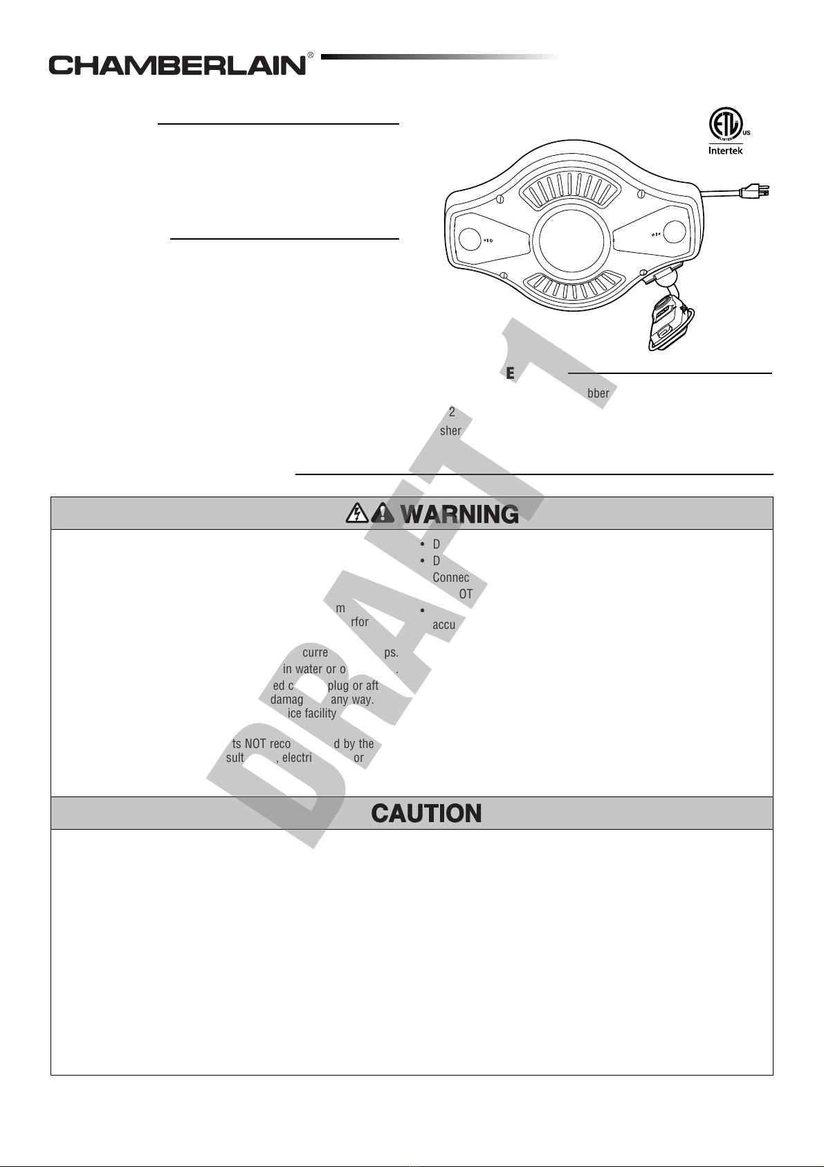
GARAGE POWER STATION
MODEL A7008890
IMPORTANT SAFETY INFORMATION
To reduce the risk of SERIOUS INJURY or DEATH:
• READ AND FOLLOW ALL INSTALLATION WARNINGS AND
INSTRUCTIONS.
• FOR INDOOR USE ONLY.
• To avoid SERIOUS PERSONAL INJURY or DEATH from
electrocution, disconnect ALL electric power BEFORE performing
ANY service or maintenance.
• DO NOT OVERLOAD RECEPTACLE. Maximum current is 10 amps.
• DO NOT immerse cords, plugs or product in water or other liquid.
• DO NOT operate appliance with a damaged cord or plug or after
the appliance malfunctions or has been damaged in any way.
Return appliance to nearest authorized service facility for
examination, repair or adjustment.
• The use of accessory attachments NOT recommended by the
appliance manufacturer may result in fire, electric shock or
INJURY to persons.
• DO NOT let inflator head touch hot surfaces.
• DO NOT use appliance for other than intended use.
• Connect to a properly grounded outlet.
• DO NOT use a 3 – 2 prong adapter.
• DO NOT use above hazardous locations or areas where water can
accumulate or in rain or mist.
• NEVER USE the inflator as a toy.
• NEVER permit children to operate or play with the Garage Power
Station. KEEP OUT OF REACH OF CHILDREN.
• Keep inflator away from flammable areas/liquids at ALL times.
• DO NOT handle work light or try to plug something into receptacle
when your hands are wet or when standing on a wet or damp
surface.
• This appliance MUST ALWAYS BE USED in accordance with all
local electrical and building codes.
To avoid personal INJURY or DAMAGE to property and to reduce the
risk of electric shock and fire:
• DO NOT use this cord reel in explosive atmospheres, near
flammable liquids or where explosion proof equipment is required.
• DO NOT direct air stream at body.
• Use ONLY recommended air-handling parts acceptable for air
pressure.
• DO NOT over-inflate.
• This inflator is designed to inflate car tires, ATV tires, motorcycle
tires, bicycle tires, sports equipment, air mattresses, beach toys
and other inflatables.
• Allow inflator to cool down 10 minutes after each 10 minutes of
continuous use.
• Use safety glasses. Use facemask or dust mask if operation is
dusty.
• DO NOT allow cord reel to retract the cord by itself as DAMAGE or
INJURY may occur from excessive rewind speed.
• BEFORE cleaning product, unplug from the power source.
• DO NOT use solvents such as gasoline, turpentine, etc. to clean
unit. Keep cord reel clean to assure smoothest operation. To clean,
simply pull cord to its full length and allow to retract through a
dampened rag. DRY thoroughly before plugging back into outlet.
• PULL out cord to full length when using the receptacle.
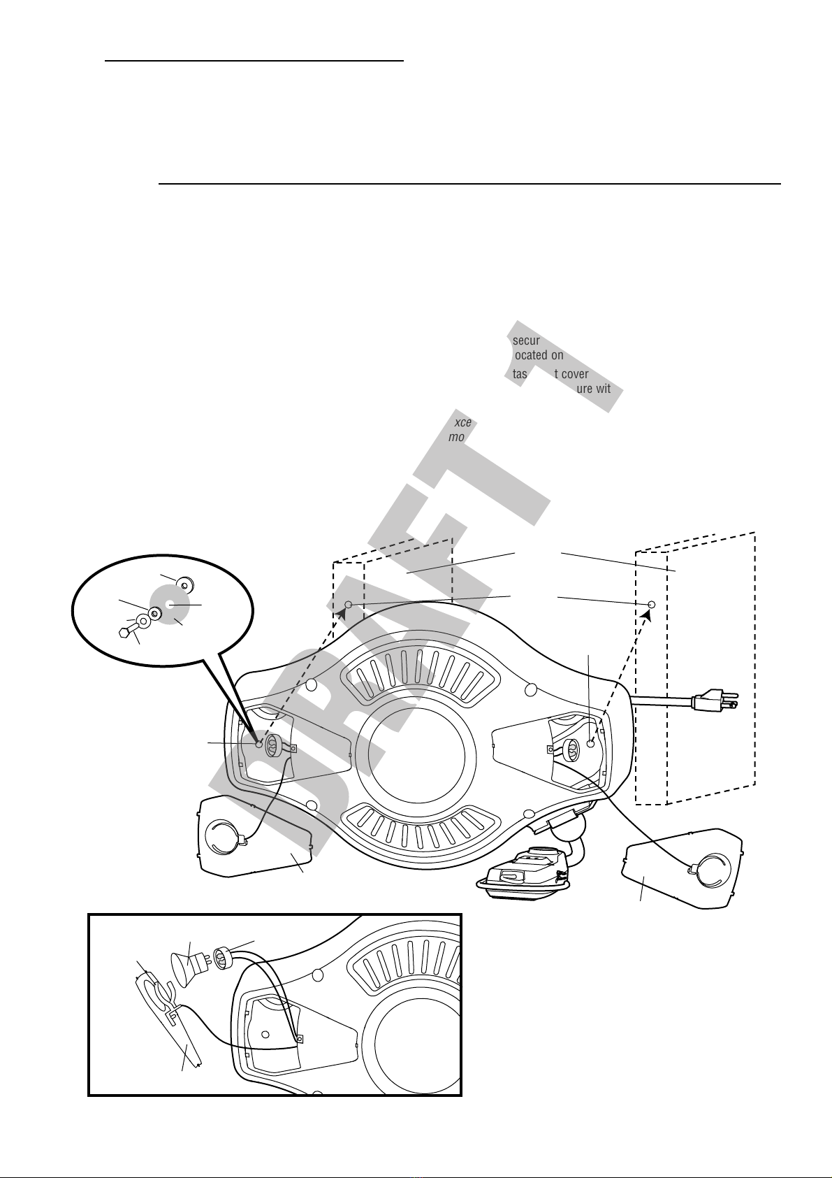
• The Garage Power Station MUST be RIGIDLY fastened to
structural support on wall or ceiling.
• Disconnect ALL electrical power BEFORE replacing bulbs.
• Use ONLY 50 watt or smaller bulb.
• For Light Duty Use Only.
CARTON INVENTORY
Garage Power Station Rubber Isolator - large (2)
¼" x 2 ½" Lag Screws (2) Rubber Isolator - small (2)
Washer (2)