VIAIR 28021 User manual

IMPORTANT:
It is essential that you and any other operator of this
product read and understand the contents of this manual
before installing and using this product.
SAVE THIS MANUAL FOR FUTURE REFERENCE
USER MANUAL
PART NO. 28021
280C AIR COMPRESSOR KIT

IMPORTANT SAFETY INSTRUCTIONS
CAUTION - To reduce risk of electrical shock or electrocution:
- Donotdisassemble.Donotattemptrepairsormodications.Refertoqualiedservice
agenciesforallserviceandrepairs.
- Donotusethisproductinorareawhereitcanfallorbepulledintowaterorotherliquid.
- Donotreachforthisproductifithasfallenintoliquid.
- Usethiscompressorwith12-voltDCsystemsonly.
- Thisproductshouldneverbeleftunattendedduringuse.
WARNING - To prevent injury:
- Neverallowchildrentooperatethiscompressor.Closesupervisionisnecessarywhenthis
compressor is being used near children.
- Thiscompressorwillbecomeveryhotduringandimmediatelyafteruse.Donottouchanypartof
this compressor with bare hands, other than the ON/OFF switch, during and immediately after use.
- Donotusethisproductnearamesorexplosivematerialsorwhereaerosolproductsarebeingused.
- Donotoperatethisproductwhereoxygenisbeingadministered.
- Do not pump anything other than atmospheric air.
- Neverusethisproductwhilesleepyordrowsy.
- Donotuseanytoolsorattachmentswithoutrstdeterminingmaximumairpressureforthat
tool or attachment.
- Neverpointanyairnozzleorairsprayertowardanotherpersonoranypartofthebody.
- ThisaircompressorisequippedwithAutomaticResetThermalProtector,andcanautomatically
restartafterthethermalprotectorresets.Alwayscutoffpowersourcewhenthermalprotector
becomesactivated.
- Wear safety glasses or goggles when operating this product.
- Useonlyinwellventilatedareas.
INSTALLATION
Pleasereadandfollowtheinstallationinstructionscarefullytoavoidinjuryordamagetothe
compressororyourvehicle.Eachofouraircompressorsandpartshavebeencarefullyproduced
andpackaged.Beforeyoubegininstallation,pleasefamiliarizeyourselfwithInstallationPartsList
(Fig. 1) of this manual.
Guidelines for Selecting Mounting Location:
The selection of proper mounting location for your air compressor will help ensure a long and
troublefreecompressorservicelife.Pleasepay close attention to the following guidelines:
1. Select a FLAT,UPRIGHTANDSECURE location where the compressor can be mounted.
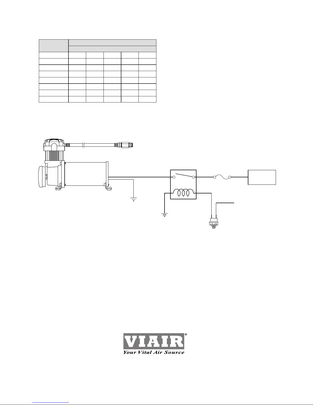
2.Tomaximizeaircompressorperformance,locatecompressorasCLOSETOTHEBATTERY
aspossiblesothatlengthofpositiveleadwirerequiredisataminimum.
3.ChoosemountinglocationthatisascoolaspossibleandAWAYFROMHEATSOURCES.
Thecoolertheambienttemperaturethelesschancethecompressorwilloverheat.
4. This compressor is moisture & splash resistant, but NOTWATERPROOF. Do not mount
compressor in locations where the unit is likely to come in contact with water.
5. Select compressor mounting location where air line can be routed from compressor air inlet
toremoteinletairlter.MakesureRemoteInletAirFilterislocatedinadrylocation,away
from water splashes.
6.Youwillalsowanttoselectcompressor’smountinglocationwheretheleaderhosebracket
can be mounted to secure the 1.5 ft. leader hose.
7. If it is necessary to mount the air compressor farther away from the battery, such as
insideyourvehicleorinthebedofyourpickup,useaminimum16AWGpositiveleadwire
for remote installation.
8.Donotmountcompressornearareaswhereammableliquidsarestored.
9.Usethreadsealantforproperttinginstallation.Teontapeisnotrecommended.
Properlysealed,recommendedtorqueis12to15ft.lbs
USER MANUAL
280C Air Compressor Kit

MOUNTING AND WIRING
1. Disconnectgroundcablefromvehicle’sbattery.
2. Temporarily position the air compressor in the location where it will be mounted.
3. Routegroundwiretothenegativepostofthebatteryortoanappropriategroundingpointand
cut ground wire to length as needed.
4. Mountaircompressorwiththefoursetsof13/64”(5mm)bolts,nuts,washers,andlocking
washersprovided.(SeeFig.2forMountingInstructions)Useofthreadsealantisrecommended.
5. NOTE:ForRemoteInletAirFilterInstallation,refertoRemoteInletAirFilterInstallation
InstructionincludedintheRemoteInletAirFilterPackforinstallationofRemoteInletAirFilter.
6. Thisaircompressorcomeswith1.5ft.heavydutyheatresistantleaderhosewith_”ttings.
Thisleaderhoseisdesignedtoprolongthelifeofyourairline.Donotremovethisleaderhose
from air compressor.
7. IMPORTANT:Pleasenote,theleaderhosethatcomeswithyourcompressormayhaveabuilt-in
inlinecheckValve.DONOTremoveinlinecheckvalvefromleaderhose.
8. Selectproperlocationtomountleaderhosewithhosebracketprovided.Avoidlocationswhere
leader hose may become tangled with wires and other hoses.
9. Tomounthosebracket,drillholewith3/16”drillbitandpushself–anchoringhosebracketpin
intohole.Routeleaderhosethroughhosebracketandsecurehosebypressingbracketclamp
into locked position.
10.Toremovehosefromthehosebracket,simplypressdownonthehoseclampreleasetabto
release bracket clamp. (Fig. 3)
11.Connectcompressorpositiveleadwiretooneoftheleadsofyourpressureswitch.
12.Makesurethatyourcompressorsetupisproperlyfused.Forappropriatefusesize,referto
ampdrawofcompressorintheSpecicationssectionofthismanual.
13.Alwayslocatefuseascloseaspossibletopowersource.
14. Before connecting to power source, re-check to make sure that all connections are
properly connected.
15.Connectandtestcompressorsystembyrunningthecompressorforashorttimetobuildup
pressure in your air tank.
16. Once air pressure reaches preset cut out pressure of your pressure switch, the compressor
will shut off. Inspect all air line connections for leaks with soap and water solution.
Ifaleakisdetected,theairlinemaynotbecutsquarelyorpushedallthewayin.
Tighten connections if needed.
(Fig. 1) Standard 280C Air Compressor Kit Installation Parts List:
A.HoseBracket(1pc)
B.MountingBolts(4pcs)
C.FlatWashers(8pcs)
D.LockingWashers(4pcs)
E.Nuts(4pcs)
F.1/4”NPTFx3/8”BarbedFitting(1pc)
G.1/4”NPTMx3/8”BarbedFitting(1pc)
H.3/8”AirLine(1pc)
I.AirLineClips(3pcs)
J. Screws (3pcs)
K.RemoteInletAirFilterwithFilterElement(1pc)
(Fig. 2) Compressor
Mounting Hardware
B.MountingBolt
C.FlatWasher
D.LockingWasher
E.Nut
K. Vibration Isolator
280C Air Compressor Kit
USER MANUAL
ABCDEFG
I
J
K
(Fig. 3) Leader Hose Bracket
L.HoseClamp
M.ClampReleaseTab
N.SelfAnchoringPin
B
C
C
D
E
K
L
M
N
H

OPERATING INSTRUCTIONS
1. IMPORTANT:AlwaysoperatethecompressoratorbelowtheMAXIMUMPRESSURERATINGof
thecompressor.PleaserefertoApplication&SpecicationsSectionsofthismanualfordetails.
2.AlwaysobservetheMAXIMUMDUTYCYCLEoftheaircompressor.RefertoCompressor
ApplicationsandSpecicationsSectionsofthismanualfordetails.Operationexceeding
maximumpressureratingsand/ordutycyclewillresultindamagetotheaircompressor.
3.YouraircompressorisequippedwithanAUTOMATICTHERMALOVERLOADPROTECTOR.
Thisfeatureisdesignedtoprotecttheaircompressorfromoverheatingandcausingpermanent
damagetoyouraircompressor.Thethermaloverloadprotectorwillautomaticallycutpowerto
youraircompressorshouldtheinternaloperatingtemperatureoftheaircompressorriseabove
safelevelsduringexcessiveuse.
4. Should at any time during use, your air compressor automatically shuts off; do not attempt to
restart the air compressor. Turn off power and allow unit to cool for about 30 minutes. This will
allowtheThermalOverloadProtectortoresetsoyoucansafelyresumeuseoftheaircompressor.
5.Topreventdischargeofyourvehicle’sbattery,andenhanceperformance,keepthevehicle’s
engine running while using the compressor.
6.Onlyoperatecompressorinwellventilatedareas.
7. The use of a relay is strongly recommended for installation of this compressor, but is not included.
(40-amprelayvalueorhigher).
MAINTENANCE & REPAIRS
1.Periodicallycheckallelectricalandttingconnections.Cleanandtightenasneeded.
2.Periodicallycheckallmountingscrews.Tightenasneeded.
3.Replaceairlterelementperiodically.Replacementfrequencydependsonoperatingfrequency
andoperatingenvironment.Forfrequentuseindustyenvironments,werecommendthatyou
replaceairlterelementatleastonceamonth.
4.Regularlycleandustanddirtfromcompressorcoolingnsandmotorhousing.
5.Youraircompressorisequippedwithpermanentlylubricated,maintenance-freemotor.
Nevertrytolubricatecompressor.
6.AllrepairsshouldbeperformedbyManufacturerorManufacturer’sAuthorizedService
Agenciesonly.
CAUTION:
Nevertouchtheaircompressororttingsconnectedtotheaircompressorwithbarehands
duringorimmediatelyafteruse.LeaderhoseandttingsconnectedtoLeaderHosewillbecome
veryhotduringandafteruse.Ifnecessary,wearheatresistantglovestohandlettings,airline,
and leader hose.
USER MANUAL
280C Air Compressor Kit
RELAY WIRING SCHEMATIC
Pressure Switch
86
Fused
12-Volt 30
To Ground
85
87 Compressor
(+) Lead

SPECIFICATIONS
280CAIRCOMPRESSORPARTNUMBERS:
•PartNo.28021/280CAirCompressor(CESpec.)
MotorVoltage: 12volts
Max.CurrentConsumption: 16amps
MotorType: Perm.Magnetic
HorsePower: 1/4
Max.WorkingPressure: 150PSI
Max.DutyCycle(@72ºF&100PSI): 30%
MinutesOn/Off(@72ºF&100PSI): 13On/30Off
Max.RestartPressure: 200PSI
Max.AmbientTemperature: 158ºF
Min.AmbientTemperature: -40ºF
Auto.ResetThermalProtection: Yes
Dimensions: 7.1”Lx3.9”Wx6.3”H
NetWeight: 6.95Lbs.
USER MANUAL
280C Air Compressor Kit

USER MANUAL
280C Air Compressor Kit
COMPRESSOR APPLICATION GUIDE
Toensurethatyougetthehighestlevelofsatisfactionfromyourcompressorperformance,referto
information below:
VIAIR COMPRESSOR REFERENCE CHART
COMPRESSORSERIES DUTYCYCLE WORKINGPRESSURE
100SERIES 15% 130PSI
215SERIES 17% 150PSI
225SERIES 20% 150PSI
265SERIES 22% 150PSI
275SERIES 25% 150PSI
300SERIES 30% 150PSI
400SERIES 33% 150PSI
450SERIES 100% 150PSI
500SERIES 33% 150PSI
550SERIES 100% 150PSI
ABOUT COMPRESSOR DUTY CYCLE:
CompressorDutyCyclereferstoamountoftimeacompressorcanbeoperatedinagiventime
period,at100PSI&atastandardambienttemperatureof72°F.
DutyCycleiscommonlyexpressedas:
CompressorOnTime/(CompressorOnTime+OffTime)
Asanexample,acompressorthatisratedfor20%dutycyclemeansthatcompressorcanbe
operatedat100PSI@72°Ffor8Minutesandrestedfor32Minutes.
8min.on/(8min.on+32min.off)=20%DutyCycle
DUTY CYCLE REFERENCE CHART
DUTYCYCLE@100PSI/72°F MINUTESON/OFF
15% 6Min.On/34Min.Off
17% 7Min.On/30Min.Off
20% 8Min.On/32Min.Off
22% 9Min.On/30Min.Off
25% 10Min.On/30Min.Off
30% 13Min.On/30Min.Off
33% 15Min.On/30Min.Off
100% ContinuousDuty
ABOUT RATED WORKING PRESSURE:
Toensuretroublefreeservicelifeofyourcompressor,alwaysoperatecompressorwithinrated
workingpressureofthecompressor.Neveruseapressureswitchwithahighercut-offpressure
thancompressor’sratedworkingpressure.

TROUBLESHOOTING GUIDE:
Tank pressure drops when
compressor(s) shut off
1.Loosedraincock
2.Checkvalveleaking
3.Looseconnections
1. Tighten drain cock
2.Replacecheckvalveor
compressor
3.Checkallconnectionswith
soap and water solution
and tighten
Compressorruns
continuouslyandairow
lower than normal
1.Excessiveairusage
2.Looseconnections
3. Worn piston ring or inlet
valve.
4.Cloggedairlterelement
1. Decrease air usage
2.Checkallconnectionswith
soap and water solution
and tighten.
3.Replacecompressor
4.Replaceairlterelement
Compressorruns
continuously causing
safetyvalve(ifequipped)
to open
1. Faulty pressure switch
2.Defectivesafetyvalve
1.Replacepressureswitch
2.Replacesafetyvalve
Excessivemoisturein
discharge
1.Excessivewaterinairtank
2.Highhumidity
1. Drain tank, tilt tank to drain.
Draintankmorefrequently
2.Movecompressortoarea
with less humidity, or use
water separator
Compressorwillnotrun 1. No power, or power switch
in OFF position
2. Blown fuse
3.Motoroverheats
4. Faulty pressure switch
(if hooked up to a
pressure switch).
1.Makesurecompressor
switch is ON
2. Disconnect compressor
from power source, replace
fuse.(RefertoSpecications
section for correct
fuse amperage)
3.Letcompressorscoolofffor
about 30 minutes to allow
thermaloverloadswitchtoreset.
4.Replacepressureswitch
Thermaloverload
protector cuts out
repeatedly
1.Lackofproperventilationor
ambient temperature is too high
2.Compressorvalvesfailed
1.Movecompressortowell
ventilatedarea,orareawith
lower ambient temperature
2.Replacecompressor
Excessiveknocking
or rattling
1.Loosemountingbolts
2. Worn bearing on eccentric or
motor shaft
3.Cylinderorpistonringisworn
1. Tighten bolts
2.Replacebearingor
piston assembly
3.Replacepistonorcompressor
CAUTION: NEVER DISASSEMBLE COMPRESSOR WHILE
COMPRESSOR IS PRESSURIZED.
USER MANUAL
280C Air Compressor Kit
PROBLEM: POSSIBLECAUSE(S) CORRECTIVEACTION

280C Air Compressor Kit
LIMITED WARRANTY:
VIAIRCorporationwarrantsthisproduct,whenproperlyinstalledandundernormalconditionsof
use, to be free from defects in workmanship and materials for a period of one year from its original
dateofpurchase.Toreceivewarrantyserviceorrepair,pleasecontactVIAIRCorporation.
Returnsshouldbemadewithinoneyearofthedateofpurchase,afteraReturnGoodsAuthorization
(RGA)numberhasbeenassignedbyVIAIRCorporation.ToobtainRGA,faxacopyofyourreceipt
to(949)585-0188.Forcompletewarrantydetails,pleasevisit:www.viaircorp.com/warranty
PLEASE NOTE:
THISWARRANTYCOVERSPRODUCTDEFECTSONLY;ITDOESNOTCOVERINCIDENTAL
ORCONSEQUENTIALDAMAGESASRESULTOFMISUSEORABUSE.
WIRE GAUGE GUIDE 12-VOLT:
AmpDraw Lengthofwirefrombatterytocompressor
10 15 20 25 30
10 14 12 10 10 10
15 12 10 10 8 8
20 10 10 8 6 6
25 10 8 6 6 6
30 10 8 6 6 4
40 86644
50 66442
60 64422
15EDELMAN•IRVINE,CA92618
TEL:(949)585-0011•FAX:(949)585-0188
www.viaircorp.com
Wiring Diagram:
(Fuse Not Included)
SINGLE “C” MODEL
COMPRESSOR WIRING DIAGRAM
15 Edelman
Irvine, CA 92618
949-585-0011
www.viaircorp.com
87
86
30
85
+-
Battery
To Keyed
Power Source
12V 40A
Relay
Fuse
Pressure
Switch
Rev.1
USER MANUAL
This manual suits for next models
2
Table of contents
Other VIAIR Air Compressor manuals

VIAIR
VIAIR 310 SS STEALTH Series User manual

VIAIR
VIAIR 100C User manual

VIAIR
VIAIR 00190 User manual

VIAIR
VIAIR 10008 User manual

VIAIR
VIAIR EXTREME Series User manual

VIAIR
VIAIR 380C User manual

VIAIR
VIAIR Exreme Series User manual

VIAIR
VIAIR 450P-A User manual

VIAIR
VIAIR 300P SXS PORTABLE POWERSPORT Series User manual

VIAIR
VIAIR 425C User manual