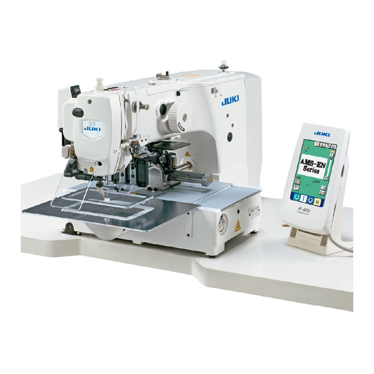
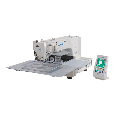
JUKI AP-874/IP-420 User manual

1
ENGLISH
INSTRUCTION MANUAL
AP-874 / IP-420
* "CompactFlash(TM)" is the registered trademark of SanDisk Corporation, U.S.A.

i
CONTENTS
I. MECHANICAL SECTION (WITH REGARD TO THE SEWING MACHINE) 1
1. SPECIFICATIONS ....................................................................................................... 1
2. CONFIGURATION ....................................................................................................... 2
3. INSTALLATION ........................................................................................................... 3
3-1. Setting up the machine..................................................................................................................3
3-2. Assembling the stacker safety pipe .............................................................................................3
3-3. Installing the air hose and air gun and adjusting the pressure................................................. 5
3-4. Thread stand assembly ................................................................................................................. 6
3-5. Installing the operation panel ....................................................................................................... 6
3-6. Locking the Pocket Folding Board...............................................................................................8
3-7. Connecting the power supply.......................................................................................................8
3-8. Installing the foot pedal.................................................................................................................9
3-9. Lubrication....................................................................................................................................10
3-10. Checking the emergency stop switch......................................................................................10
3-11. Removing the styrene foam of the pocket setting plate......................................................... 11
3-12. Installing the label vacuum device........................................................................................... 11
3-13. Mounting the Pattern ................................................................................................................. 11
3-14. Installing the guide bar..............................................................................................................12
3-15. Break-in operation .....................................................................................................................12
4. OPERATION .............................................................................................................. 13
4-1. How to install the needle.............................................................................................................13
4-2. Threading the needle thread.......................................................................................................14
4-3. Installing / removing the bobbin case........................................................................................15
4-4. Setting a bobbin into the bobbin case.......................................................................................15
4-5. Winding a bobbin.........................................................................................................................16
4-6. Thread tension .............................................................................................................................18
4-7. Thread take-up spring .................................................................................................................19
4-8. Adjustment procedure for the pocket setting device ............................................................... 20
4-9. Operation procedure....................................................................................................................22
5. EMERGENCY STOP SWITCH .................................................................................. 23
II. OPERATION SECTION (WITH REGARD TO THE PANEL) .................... 24
1. PREFACE .................................................................................................................. 24
2. WHEN USING IP-420 ................................................................................................ 28
2-1. Name of each section of IP-420 .................................................................................................. 28
2-2. Buttons to be used in common ..................................................................................................29
2-3. Basic operation of IP-420 ............................................................................................................ 30
2-4. Liquid crystal display at the time of sewing pattern selection................................................ 31
(1) Sewing pattern data input screen ...............................................................................................31
(2) Sewing screen ............................................................................................................................33
2-5. Replacing the pattern ..................................................................................................................35
2-6. How to select the sewing pattern ............................................................................................... 37
2-7. Pattern checking procedure........................................................................................................39

ii
2-8. Changing item data......................................................................................................................40
2-9. Performing modication of needle entry point ......................................................................... 42
2-10. Setting the AUTOMATIC/STEP .................................................................................................. 43
2-11. How to change the setting position..........................................................................................44
2-12. How to use temporary stop.......................................................................................................45
(1) To continue performing sewing from some point in sewing ........................................................ 45
(2) To perform re-sewing from the start............................................................................................46
(3) Re-starting the setting operation................................................................................................. 47
2-13. Lowering the presser.................................................................................................................48
2-14. Stacker operation (taking out the material)............................................................................. 49
(1) Taking out the material from the stacker .................................................................................... 49
(2) Adjusting the stack-full sensor ....................................................................................................49
2-15. Using counter.............................................................................................................................50
(1) Setting procedure of the counter ................................................................................................50
(2) Count-up releasing procedure ....................................................................................................52
(3) How to change the counter value during sewing ........................................................................52
2-16. Performing new register of users’ pattern............................................................................... 54
2-17. Naming users’ pattern ...............................................................................................................55
2-18. Performing new register of pattern button.............................................................................. 56
2-19. LCD display section at the time of pattern button selection ................................................. 57
(1) Pattern button data input screen................................................................................................. 57
(2) Sewing screen ............................................................................................................................59
2-20. Performing pattern button No. selection ................................................................................. 61
(1) Selection from the data input screen ..........................................................................................61
(2) Selection by means of the shortcut button.................................................................................. 62
2-21. Changing contents of pattern button.......................................................................................63
2-22. Copying pattern button .............................................................................................................64
2-23. Changing sewing mode.............................................................................................................65
2-24. LCD display section at the time of combination sewing........................................................ 66
(1) Pattern input screen....................................................................................................................66
(2) Sewing screen ............................................................................................................................68
2-25. Performing combination sewing ..............................................................................................70
(1) How to create new combination data.......................................................................................... 70
(2) How to add combination data .....................................................................................................71
(3) Deleting procedure of the combination data ...............................................................................72
(4) Deleting procedure of the step of the combination data .............................................................72
2-26. Using the simple operation mode ............................................................................................73
2-27. LCD display when the simple operation is selected...............................................................74
(1) Data input screen (individual sewing) .........................................................................................74
(2) Sewing screen (individual sewing)..............................................................................................77
(3) Data input screen (combination sewing).....................................................................................80
(4) Sewing screen (combination sewing) .........................................................................................82
2-28. Changing memory switch data.................................................................................................84
2-29. Using information ......................................................................................................................85
(1) Observing the maintenance and inspection information.............................................................85
(2) Releasing procedure of the warning ...........................................................................................86
iii
2-30. Using communication function ................................................................................................87
(1) Handling possible data ...............................................................................................................87
(2) To conduct communication by means of the CompactFlash (TM)..............................................87
(3) Performing communication by using USB ..................................................................................87
(4) Take-in of the data ...................................................................................................................... 88
(5) Taking in plural data together...................................................................................................... 89
2-31. Performing formatting of the media.........................................................................................91
3. MEMORY SWITCH DATA LIST ................................................................................. 92
4. ERROR CODE LIST .................................................................................................. 95
5. MESSAGE LIST ...................................................................................................... 102
III. MAINTENANCE OF SAWING MACHINE.............................................. 105
1. MAINTENANCE....................................................................................................... 105
1-1. Adjusting the height of the needle bar..................................................................................... 105
1-2. Needle and hook adjustment .................................................................................................... 105
1-3. Counter knife..............................................................................................................................106
1-4. Positioning the counter knife and the knife thread guide...................................................... 107
1-5. Thread take-up amount adjustment ......................................................................................... 107
1-6. Holder pressure adjustment .....................................................................................................107
1-7. Hook oil amount (track of oil) adjustment ............................................................................... 108
1-8. Adjusting the oil amount in the face plate...............................................................................109
1-9. Replacing the oil in the machine head..................................................................................... 110
1-10. Cleaning the vacuum lter ...................................................................................................... 110
1-11. Removing dust from the face part of the machine head ...................................................... 111
1-12. Cleaning the lter in the electrical box .................................................................................. 111
2. TROUBLE SHOOTING............................................................................................ 112
3. OPTIONAL............................................................................................................... 114
3-1. Garment body rack .................................................................................................................... 114
3-2. Marking light............................................................................................................................... 115

– 1 –
1) Sewing area : X (lateral) direction 250 mm, Y (longitudinal) direction 250 mm
2) Max.sewingspeed :4,000sti/min(accordingtosewingspecications)
3) Stitch length : 0.1 to 6.0 mm (Minimum resolution: 0.05 mm)
4) Main shaft of machine head drive unit : AC servo motor
5) Presser plate travel : Continuous feed (Stepping motor with an encoder)
6) Needle bar stroke : 35 mm
7) Needle : SCHMETZ 134 SERV 7 Nm : 130
8) Hook : Full-rotary exclusive hook (forced lubrication)
9) Bobbin case : Bobbin case exclusively designed for a full-rotary 1.7-fold hook
(provided with an idling prevention spring)
10) Lubrication oil : Machine head : New Defrix Oil No. 1
11) Thread trimming mechanism : Scissors cutting mechanism using a counter knife and a moving knife
(Driven by grooved cam motor)
12) Pattern data stored in memory : Main body and a media
・Main body: Max. 999 patterns
・Media: Max. 999 patterns
13) Dimensions : 1,890 mm (W) x 1,510 mm (L) x 1,155 mm (H)
(excluding the thread stand)
14) Temporary stop function : It is possible to stop the sewing machine during sewing.
15) Bobbin counter : Up/down method (0 to 9999)
16) Sewing counter : Up/down method (0 to 9999)
17) Stitch number counter : Up/down method (0 to 9999)
18) Memory backup amount : Patterns are automatically stored in memory at the time of power
shutdown.
19) Mass (Total weight) : 558 kg
20) Power consumption : 820 VA
21) Working temperature range : 5°C to 35°C
22) Working humidy range : 35% to 85% (with no dew condensation)
23) Supply voltage : Rating ±10% 50 / 60 HZ
24) Compressed air : 0.5 MPa
25) Air consumption : 220 dm 3/min (ANR)
26) Noise : - Equivalent continuous emission sound pressure level (LpA) at the
workstation :
A-weighted value of 83.0 dB; (Includes KpA = 2.5 dB); according to
ISO 10821- C.6.3 -ISO 11204 GR2 at 4,000 sti/min.
- Sound power level (LWA) ;
A-weighted value of 90.5 dB; (Includes KWA = 2.5 dB); according to
ISO 10821- C.6.3 -ISO 3744 GR2 at 4,000 sti/min.
1. SPECIFICATIONS
I. MECHANICAL SECTION (WITH REGARD TO THE SEWING MACHINE)

– 2 –
❶Sewing machine head
❷Pocket setting plate
❸Presser plate
❹Operation panel
❺Conveyor and X-Y unit
❻Pocket cloth holding board
❼Electrical box
❽Power switch
❾Stacker
Bobbin winder
Thread stand
Presser arm
Start switch
Emergency stop switch
Temporary stop switch
Presser plunger
Pedal
2. CONFIGURATION
* If emergency stop switch is pressed while the device is in operation, the blower motor will not stop, but the power
to the device will be turned OFF and the device will stop.
❶
❸
❷
❹
❻
❼
❽
❾
❺

– 3 –
1) Installthemachineonaatplacewithleveled.
2) Loosen nut and turn level adjuster to lift the
machine until caster idles.
3) After the machine has been set up properly, tighten
nut andxleveladjuster.
3. INSTALLATION
3-1. Setting up the machine
1)
Fix stacker safety pipe on the main body by means of pipe clamp and setscrews .
2)
Insert two pipes into pipe joint andxwithscrewsand nuts .
3-2. Assembling the stacker safety pipe

– 4 –
(1) Removing the sewing product
1)
To remove the sewing product from the sewing ma-
chine, press stacker lever release button
on the sewing screen to release the stacker presser
lever.
The screen changes over to “stacker release
screen”.
When the cancel butto is pressed after
the removal of the sewing product, the screen is
changed over to the sewing screen and the stacker
presser lever closes.
Sewing screen Stacker release screen
2)
Adjust the stacking quantity by loosening the screw
of sensor of work clamp cylinder and chang-
ing the sensor position. Stacking quantity will be
increased by moving the sensor position upward.
The sensor should be adjusted so that
approximately 60 sewing products are
stacked on the stacker.

– 5 –
When opening valve , be aware that the air-supplied mechanism is partly activated.
If the air supply source pulse is too large, even at the above setting value the emergency
signal might go off.
3-3. Installing the air hose and air gun and adjusting the pressure
(Open) (Shut)
(1) Connecting the air
hose
1) Connect fitting to plug
. At this time, wrap
sealing tape or the like
round the screw.
2) Insert air hose into fit-
ting and fasten them
with hose band .
(Use the correct air hose
tomatchthetting.)
(2) Connecting the air gun
Insert the coil tube of air gun into quick-coupling joint and put the air gun on
L-shapedtting.
(3) Opening/closing the valve
To open/close valve , turn the valve until it will go no further (by 90 degrees of an
angle).
(4) Adjusting the supply air pressure
1) The operating air pressure should be set to 0.5 MPa.
2) Deliberately open valve .
3) Lift regulator knob in direction . Turning it in this state will change the sup-
ply air pressure. Turn knob in direction (+) or in direction (–) so that black
point of pressure gauge indicates 0.5 MPa. After the adjustment, lower knob
in direction to securely lock it.
(5) Pressure drop signal adjustment
1) Set the pressure at which an emergency signal will go off if the pressure drops below it.
2) The normal setting value is 0.4 MPa.
3) Insert a small screwdriver into cap of pressure gauge , and adjust screw which is inside. Turn the
screw with the screwdriver until the green pointer points to 0.4 MPa.
(6) Discharging the drainage
1) Remove the drain from regulator before use to discharge water (by loosening knob ).
2) Water adversely affects the air control components. It is therefore necessary to carefully remove the water.
3) If the air pressure in regulator drops, the pressure gauge switch comes on to cause an error.

– 6 –
1) Set the thread stand in the hole at the right corner
of the table.
2) Insert thread stand rob into thread stand thread
guide .
3) Tighten lock nut so that the thread stand will not
be able to move.
4) If ceiling wiring is possible, pass the power cord
through thread stand rod .
3-4. Thread stand assembly
3-5. Installing the operation panel
1) Loosen cord clamp . Remove panel cord .

– 7 –
If the IP-420 screen is not easily visible,
loosen setscrews ❻and adjust the po-
sition of the operation panel mounting
base.
3)
Loosen setscrews ❻of operation panel mounting
pipe ❺. Determine the position of operation panel
mounting base ❼ and x it that position with set-
screws ❻.
Bundle operation panel cord ❷with cord clamp ❶.
Fix operation panel mounting base ❼, supplied
with the unit, in position with setscrews ❽.
4)
Open cover ❾of the IP-420. Insert cable into
the IP-420.
5)
Route cable down along the IP-420 and close
cover ❾.
6)
Place the IP-420 on operation panel mounting base
❼.
2) Remove setscrews ❸. Fix operation panel cable
support bar ❹with setscrews ❸.
❺
❼
❻
❾
❼
❶
❶
❷
❽
❸
❹
❷

– 8 –
1) Mount the pocket folding board on the pocket
folding board pipe .
2) Lock the pipe to the pocket folding board using the
pipe setscrew .
Green/yellow
(grounding)
Red(AC)
White(AC)
Black(AC)
Green/yellow
(grounding)
Light blue (AC)
Brown (AC)
3-phase
Single-phase
1) The machine is not supplied with a power plug. It
is therefore necessary for you to select a plug that
matches the receptacle available under a given
operating environment and attach it to the power
cable.
2) Two different kinds of power sources, i.e.,, the
3-phase one and the single-phase one are
prepared for this machine. Use the power source
which matches the electric voltage specication of
the machine.
3-7. Connecting the power supply
3-6. Locking the Pocket Folding Board

– 9 –
1) Connect connector of pedal supplied with the
unit to pedal junction connector .
3-8. Installing the foot pedal
2) Install pedal ground wire on solenoid valve
mounting plate with ground wire setscrew .

– 10 –
Removellercap.AddJUKINewDefrixOilNo.1throughllopeninguntil the oil level reaches the center of
oil gauge .Inaddition,whenyoubringanewmachineintouse,besuretosupplyoilthroughllopeningby
approximately 10 cc beforehand.
3-10. Checking the emergency stop switch
When the red button of emergency stop switch is
strongly pressed as far as it goes, the switch is placed
in its ON state. When the button is turned clockwise,
the switch is placed in its OFF state.
Check to be sure that emergency stop switch is in its
OFF state.
If emergency stop switch is in its ON state, the op-
eration panel screen will not light up even if the power
switch is turned ON.
Emergency stop switch
OFF state
Emergency stop switch
ON state
3-9. Lubrication
Be sure to use JUKI genuine oil. If you use any oil other than the specied oil, a trouble can
result.

– 11 –
For the mounting of pattern, refer to "II-2-5. Replacing the pattern" p.35.
3-13. Mounting the Pattern
3-11. Removing the styrene foam of the pocket setting plate
1) Remove binding cord . Supply air to the machine
and turn the power ON.
2) Press Set Ready key .
3) If error No. 371 is displayed on the operation panel,
press Reset button .
4) After pocket setting plate has reached its upper
end, remove foamed polystyrene from the pock-
et setting plate and turn the power OFF.
3-12. Installing the label vacuum device
Label suction opening isxedwithadhesivetape.
When using labels for sewing, remove adhesive tape
and turn the suction opening upward. Adjust the
position of the suction opening to the label position,
and install it on the underside of the sewing table.

– 12 –
3-15. Break-in operation
1)
Display the main motor revolutions check screen.
Press the key. The main motor revolutions check button
Aappears on the screen. Press this button to display the
main motor revolutions check screen.
A
C
D
E
B
2)
Run the main motor to break in the machine.
It is possible to set the number of revolutions by means of + and
-buttons Band C.
Press the key to run the machine at the number of revolu-
tions you have set.
At this time, the number of revolutions measured by the machine
is displayed on D.
Press reset button Eto stop the sewing machine.
Set the number of revolutions for the break-in operation at 2000.
3-14. Installing the guide bar
Securely insert the thread guide bar into the hole in the
top cover in the orientation as shown in the gure at the
left.
To use a new machine or the machine after an extended
time of disuse, be sure to run in the machine for approxi-
mately 30 seconds to one minutes.

– 13 –
Use a SCHMETZ 134 SERV 7 Nm : 130 needle
1) Turn handwheel to lift needle bar to its high-
est position.
2) Loosen needle setscrew and turn needle so
that its indentation is on the handwheel side.
3) Push the needle deeply into the hole in the needle
bar, in the direction of the arrow, until it hits the sur-
face at the far end of the hole.
4) Tighten the needle setscrew very tightly.
5) Check to make sure that long groove of the nee-
dle is on the face plate side.
4. OPERATION
WARNING :
Turn OFF the power before starting the work so as to prevent accidents caused by abrupt start of the
sewing machine
4-1. How to install the needle

– 14 –
1) Thread the needle thread through the points shown
inthegure,intheorderofthenumbers.
2) Pull out about 10 cm of the thread that passes
through the needle.
3) For threading the thread while power is ON, please
refer to the section on threading.
WARNING :
Turn OFF the power before starting the work so as to prevent accidents caused by abrupt start of the
sewing machine
4-2. Threading the needle thread
Pass the thread over the front side of
the disc of thread guide .

– 15 –
1) Fully raise latch of bobbin case until it stops,
and take the bobbin case out of the hook. The bob-
bin fitted in bobbin case will not come off the
bobbin case by holding latch withngers.
2) To install the bobbin case in the hook, be sure to
raise latch andfullytthebobbincaseoverthe
hook driving shaft. Then release latch to let it
down.
WARNING :
Turn OFF the power before starting the work so as to prevent accidents caused by abrupt start of the
sewing machine
4-3. Installing / removing the bobbin case
4-4. Setting a bobbin into the bobbin case
Please use the accessory exclusive
bobbin case. Also, if it is not pushed in
far enough, bobbin case might fall
out during sewing. So, be careful.
1) Hold the bobbin in a way that the thread open end
is directed to the right as observed from you, and
set the bobbin into the bobbin case.
2) Pass the thread through thread slit , and pull the
thread in direction . By so doing, the thread will
pass under the thread tension spring and come out
from notch .
3) Check that the bobbin rotates in the direction of the
arrow when bobbin thread is pulled.

– 16 –
Pass thread coming from the thread stand through ten-
sion controller and wind the thread on the bobbin.
1) Fit bobbin over bobbin winding shaft .
2) Pass the thread as illustrated in the figure, and
wind the thread round bobbin four or ve times in
the direction of arrow .
3) Push bobbin presser toward the bobbin (in
the direction of arrow ), and the bobbin winder
will start winding the bobbin. It will automatically
stop winding the bobbin when the predetermined
amount of thread has been wound round the bob-
bin (80% of the outside diameter of bobbin).
4) To adjust the amount of thread to be wound round
the bobbin, loosen screw and change the po-
sition of the bobbin presser. (Moving the bobbin
presser in the direction of arrow will increase the
amount of thread to be wound round the bobbin.)
4-5. Winding a bobbin
1. The bobbin winder will not actuate
unless breaker of the seesaw type
switch is in its ON state (where the
white engraved marker dot can be
observed). It means that you can
use breaker as the bobbin winder
switch.
2. There are times when even when
breaker is ON (the white dot is vis-
ible), the bobbin winder fails to oper-
ate. This means that inside, the break-
er is actually OFF. Turn the breaker
OFF and back ON.
3. Be sure to use the JUKl’ s genuine
bobbins and bobbin cases.
4. When threading the bobbin thread
from thread guide arm to tension
controller , x thread stand disc
in such a position that the disc and
arm do not interfere with the bobbin
thread path between and .
Table of contents
Other JUKI Sewing Machine manuals

JUKI
JUKI AMS-210EN-7450 User manual

JUKI
JUKI LH-3500A series User manual

JUKI
JUKI MO-204D User manual

JUKI
JUKI PLC-2710V User manual

JUKI
JUKI SC-810 User manual

JUKI
JUKI L-1A User manual

JUKI
JUKI LK-1900B series User manual

JUKI
JUKI M-1 Series User manual

JUKI
JUKI TL-98E User manual

JUKI
JUKI LU-2810 Series Quick start guide

JUKI
JUKI MO-735N User manual

JUKI
JUKI MEB-3200 Series Quick start guide

JUKI
JUKI MP-200N User manual

JUKI
JUKI DDL-8700B-7 User manual

JUKI
JUKI AMS-221EN Series Quick start guide

JUKI
JUKI NA-11UT Series User manual

JUKI
JUKI IP-310 User guide

JUKI
JUKI LU-1510 User manual

JUKI
JUKI IP-100A Quick start guide

JUKI
JUKI TL-98Q User manual