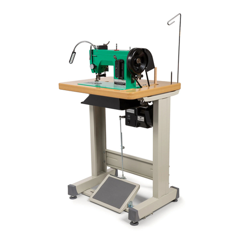
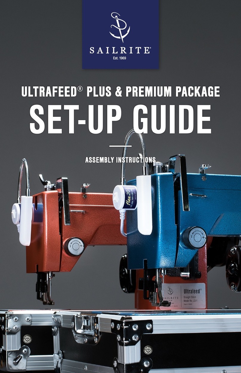
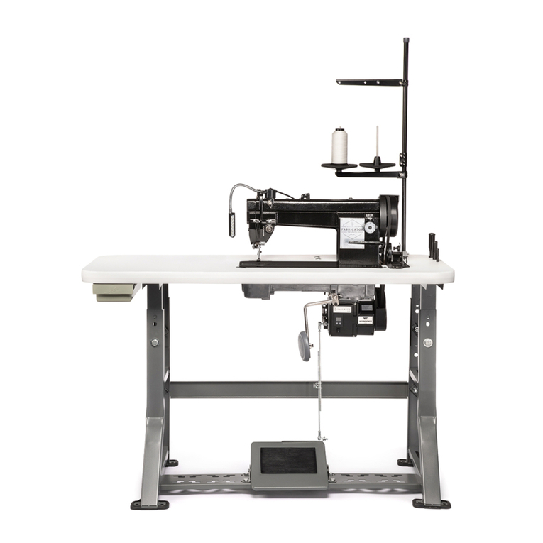
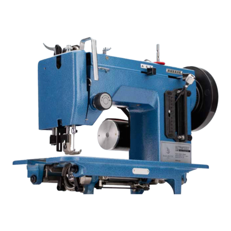
Sailrite Fabricator User manual

Set-Up • Use • Maintenance
Troubleshooting • Schematics

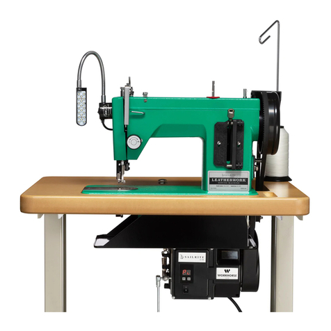
Welcome to Your Fabricator Sewing Machine!
The Fabricator is a production machine that can
sew all day with its best-in-class power system.
Add in its slow speed power and control, which allows you to truly sew
stitch-by-stitch, and you’ve got yourself a new trusty sidekick for all your
canvas and upholstery projects.
This guidebook will give you in-depth knowledge of your machine including
getting set-up, sewing, advanced maintenance and troubleshooting.

Table Of Contents
Sewing Machine Safety............................................... 1
Sailrite Fabricator Set-Up .......................................... 2
Power Stand Assembly .............................................. 3
Installing the Drawer................................................... 5
Installing Rubber Foot Pads ....................................... 6
Installing the Treadle .................................................. 7
Installing the Linkage Bar ........................................... 8
Oil Pan and Machine Installation................................ 9
Check Motor Rotation............................................... 11
Securing the Stitch PRO Balance Wheel ................. 12
Belt Adjustment for the Workhorse Servo Motor ...... 13
Attaching the Balance Wheel Belt Cover ................. 14
Attaching the Bobbin Winder.................................... 15
Mounting the Led Light............................................. 16
Mounting the Thread Stand...................................... 16
Installing the Knee Lift Assembly.............................. 17
Check the Machine for Operation............................. 18
Auto Lubrication .......................................................19
Manual Oiling ...........................................................21
Coordinating the Needle, Thread and Material
Installing Needles ..................................................... 25
Thread Recommendations ....................................... 26
Preparing to Sew
How to Wind a Bobbin.............................................. 28
Bobbin Thread Winding Adjustment ......................... 30
Removing and Installing the Bobbin Case ............... 31
How to Thread the Bobbin........................................ 32
Threading the Sewing Machine................................ 33
Pulling Up the Bobbin Thread................................... 35
Sewing with the Sailrite Fabricator
Starting to Sew ......................................................... 36
Setting the Stitch Length &
Operating in Reverse ............................................... 37
Adjusting the Pressure of the Presser Feet.............. 38
Adjusting Upper Tension Assemblies ....................... 39
Adjusting Bobbin Thread Tension............................. 40
Removing Material from Under the Presser Feet..... 41
Sewing in Light to Moderate Weight Fabrics............ 41
Fabricator Maintenance
Feed Dog Height Adjustment ................................... 43
Setting the Feed Dog Position.................................. 44
Adjusting Needle Position & Clearance
Between Presser Feet.............................................. 45
Timing Between the Needle & the Rotating Hook .... 46
Adjusting the Presser Foot Lift ................................. 50
Adjusting the Vertical Lift
of the Outer Presser Foot......................................... 51
Adjusting Feed Timing of the Needle Bar,
Presser Foot and Feed Dog ..................................... 52
Stitch Length Adjustment Between
Forward & Reverse .................................................. 53
Adjusting the Thread Take-Up Spring....................... 54
Troubleshooting
Skipped Stitches....................................................... 56
Lack of Stitch Tension............................................... 57
Schematics.................................................................58
Machine Specications............................................. 75
Warranty ..................................................................... 76
1 | Sailrite.com
SEWING MACHINE SAFETY
• Do not operate in conditions where you or the
machine are or may become wet.
• Operate the machine on a rm, level surface
where there is adequate room for safe
operation.
• Observe caution when placing your hands
or other parts of your body or clothing near
any moving parts including but not limited to
the following: the walking foot, the needle,
the drive belt, the balance wheel and any of
its parts.
• Do not run the machine without its covers.
• Do not stop the movement of the balance
wheel with your hands.
• Use caution in tilting the machine backwards
in its table and in lowering it back into the
table.
• Use proper lifting techniques when moving
the machine.
• Do not drop the machine.
• Always use the proper voltage required for
the motor and light.
• Wear protective eyewear when sewing.
• Wear shoes when operating the foot
pedal.
• Provide supervision when allowing others to
use the machine—particularly children and
those who are unfamiliar with the machine’s
operation.
• Do not use around ammable materials.
• Use both hands to feed and guide the
material while the belt and balance wheel
are in motion.
• Maintain a safe distance from the belt and
balance wheel when the machine is in motion.
• The operator’s hand should not be near the
wheel pinch point (where moving parts may
cause harm to the user) except to raise and
lower the needle, and only when the motor is
disengaged.
Please observe the following when using your Sailrite sewing machine
WARNING: Some products may be fabricated from materials which may contain chemicals
known to the state of California to cause cancer, birth defects or other reproductive harm.

Sailrite Fabricator Guidebook | 2
Our expert Sailrite technicians have checked and adjusted every component of this machine. It has
been sewn off and all accessories have been prepared for easy installation. With this guidebook,
you should be able to maintain and adjust your own machine. Please do not make substantial
adjustments to machine settings unless in consultation with Sailrite.
Unpacking the Sailrite Fabricator
To remove the casting from the box, it is best
to have help. While one person holds the box
down on the oor, the other should reach under
the arm of the machine and lift straight up. Set
the machine on a solid surface or oor.
Tip: Place a newspaper or old towel down rst
to absorb any oil and protect the surface.
SAILRITE FABRICATOR SET-UP
Inspecting the Machine
Before use, thoroughly inspect the machine. It
will arrive threaded with a fabric sample under
the presser feet. To remove the fabric, untie the
thread from the top of the machine and lift the
presser feet with the hand lever (A). Make sure
the needle is up, out of the fabric and pull the
sample and all thread free from the top of the
machine. Cut the bobbin thread and let it lay
loose. See page 41 for complete steps.
1
A

3 | Sailrite.com
Power Stand Assembly
1. Find parts A, B, Cand D. Stand both k-legs
upright and bolt the back support bar (E) to
the bottom hole at the back of the table legs
(Figure 2).
2. Find parts F, Gand H. Flip the legs
upside-down and place the treadle mount
bar (I) at the back of the forward most slots
(Figure 3). Bolt the treadle mount bar to the
bottom surface of each crossbar of the k-legs
(Figure 4).
2
3
GF H
A
B
C
FRONT
D
4
E
I

Sailrite Fabricator Guidebook | 4
5
6
7
1.5"
0.5"
J
M
K L
3. Place the top of the table on the oor with
the laminate surface down. Place on a soft
surface to avoid scratching the tabletop.
Squarely line up the table legs as shown
(Figure 5). Be sure that the legs are facing
the correct direction. Reference the cutout
shape in the tabletop to aid in placement.
4. Use a pencil to mark screw locations for
attaching the K-leg frame to the tabletop
(Figure 6). Use a 5/32" drill bit and drill
about 1/2" into the tabletop. Do not drill
completely through.
5. Bolt the frame to the bottom of the tabletop
using the enclosed hex head lag screws (J),
locking washer (L) and washer (M) to lock at
each position (Figure 7).

5 | Sailrite.com
Installing the Drawer
The drawer mounts to the forward, left,
underside of the table when the stand is upright.
To install the drawer, locate the rough position
(Figure 8) and put the drawer rails and the
drawer in position. The drawer should pull open
from the front of the table (Figure 9) and when
pushed in, it will hit a stop. Secure the rails to the
underside of the table with the included screws
(K) on page 4 (Figure 10).
Tip: Do not over tighten the screws or they will
prevent the drawer from sliding freely.
10
9
FRONT
Drawer Location
8
FRONT

Sailrite Fabricator Guidebook | 6
Installing Rubber Foot Pads
Stretch the K-Leg foot pads onto the rectangular
metal feet of the table legs (Figure 11).
Flip the table upright.
If the height needs adjusted, move the bolts up
or down in the leg slots and holes then lock in
place (Figure 12). Be sure to adjust the height
before placing the sewing machine casting in
the tabletop.
Be sure all nuts and bolts are tight.
11
12

7 | Sailrite.com
Installing the Treadle
The treadle is typically installed near the center
of the treadle mount bar, but it can be set to the
user’s preference anywhere on the bar.
After determining placement and taking note of
desired location of the treadle, ip the table onto
its back side (Figure 13).
The two end pivots (A) t into the sides of the
treadle pedal and are then bolted to the mount
bar with 4 bolts to hold it in position (Figure
13-14).
The rubber pad will be face up and the side with
the bolt holes will be to the back of the table
(away from the machine operator). These holes
will be used to attach the treadle to the motor.
Tip: Install the pivots rst but do not tighten
completely. Then place the treadle in position
between the pivots and tighten bolts. Flip the
table upright and check to make sure the treadle
moves freely after the bolts are tightened.
BEFORE CONTINUING: See “Attaching
a Pulley” and “Installing the Workhorse
Servo Motor” in the Workhorse Servo Motor
Instructions.
A
13
14

Sailrite Fabricator Guidebook | 8
Installing the Linkage Bar
Bolt the L-bracket (B) to the holes on the back
of the treadle so that its shorter leg is sticking
out toward the back of the table pointing toward
the Workhorse motor. (Figure 15). The short leg
should be roughly vertical to the motor operation
lever (C).
Bolt the linkage bar (D) to the outer most hole of
the motor operation lever on the Workhorse and
the L-bracket (Figure 16).
By increasing or decreasing the overlap of the
linkage bar, different treadle pedal angles can
be achieved. Use a size 14mm wrench to set
the angle to your preference (Figure 17).
B
C
D
15
16
17

9 | Sailrite.com
Oil Pan and Machine Installation
Locate the two back corner cushions (A), the
two front corner cushions (B) and the two hinge
cushions with chrome hinges (C).
Take out the cast aluminum oil tray (D) and slide
the four corner cushions onto each respective
corner ange (Figure 18-19).
With the table upright, tilt the tray into the
tabletop cutout so that all four corner cushions
drop down into the ledges. The edge of the oil
tray with the crescent cutout should be facing
the left side of the table, away from the belt slot.
(Figure 19).
D
A
AA
B
BB
C
18
19

Sailrite Fabricator Guidebook | 10
Push the machine Support Pin (E) into the hole
in the tabletop nearest the carriage bolts holding
the motor. The t may be tight so just push until
snug (Figure 20).
Insert the tapered end of the knee lift post
connector (F) into the raised hole in the bottom
of the oil tray (G) (Figure 21).
Find the magnet for the oil tray (H) and place it
in the bottom of the oil tray (Figure 21).
Next, take the rubber pads off of the chrome
hinges (C) and place them into their respective
tabletop cavities (I). Insert the two chrome
hinges into the two holes located on the back
side of the sewing machine (J).
With help, lift and lower the sewing machine into
the tabletop so that the chrome hinges t into
the rubber pads (Figure 22).
E
F
G
H
20
21
22
I
J

11 | Sailrite.com
Check Motor Rotation
The machine’s motor shaft should rotate
counterclockwise when viewed from the motor
shaft end. Plug in the motor, switch the power
on and press down on the foot treadle to conrm
operation now.
If motor rotation is not counterclockwise, please
refer to “Changing Motor Rotation” in the
Workhorse Installation Instructions.
23

Sailrite Fabricator Guidebook | 12
Securing the Stitch PRO
Balance Wheel
Remove the Posi-Pin (wrapped in plastic) from
the Posi-Pin Wheel Bushing on the upper shaft
of the sewing machine.
Remove the three screws (A) for the belt cover
installation (Figure 24). Position the C-shaped
belt guard and reinstall the screws making sure
washers are positioned as shims behind the
guard to keep it from being bent out of shape
(Figure 25).
Unscrew the reverse-threaded Posi-Pin Nut
(B). Slide the Stitch PRO Balance Wheel onto
the Posi-Pin Wheel Bushing (C), making sure
it does not interfere with the belt cover. If the
wheel hits the belt cover, reposition the washers
placed under the C-shaped belt guard or move
the bushing out further by loosening the set
screws in the bushing.
Thread the reverse-threaded nut back onto
the bushing and tighten by hand. Rotate the
balance wheel until the hole in the balance
wheel is aligned with one of the four bushing
holes. Push the Posi-Pin (D) through the holes
to lock the balance wheel to the bushing (it will
spring back slightly). Rotation of the balance
wheel will now cause the machine to function
(Figure 26).
24
A
25
B
C
D
26

13 | Sailrite.com
Belt Adjustment for the
Workhorse Servo Motor
Before installing the drive belt, loosen the hex
head set screw (A) with a 5/32" Allen wrench
to allow the Workhorse Servo Motor to freely
pivot (Figure 27). This will prevent the belt from
stretching or breaking while being installed.
With the machine tilted back, slip the drive
belt over the balance wheel track and guide
it onto the motor pulley then carefully lower
the machine into the cutout while judging belt
tension (Figure 28). If the tension needs to be
adjusted, follow the directions below:
Pivot the motor back to tighten the belt and
forward to loosen it. Proper adjustment of the belt
results in 3/8" of slack when pressed by nger at
its center. Retighten set screw (A). The Linkage
Bar may also need to be readjusted (page 8).
Once installed, the belt should not touch the
table and should be centered on the track of
both the balance wheel and motor pulley. Adjust
the positioning of the motor left and right by
loosening and sliding the bolts within the slots of
the motor bracket.
Once the motor is in the correct position and
all bolts are tightened, remove the belt so the
pulley bracket can be installed.
BEFORE CONTINUING: See “Installing the
Pulley Cover” in the Workhorse instructions.
28
A
27

Sailrite Fabricator Guidebook | 14
Attaching the Balance
Wheel Belt Cover
Locate the remaining portion of the belt cover
(Figure 29). It has a keyway (B) that locks onto
post (C) of the C-shaped belt guard that was
secured to the machine earlier (Figure 30).
Connect the covers and remove the remaining
screw in the machine casting (D) which is below
the Stitch PRO Balance Wheel. Reinstall this
screw through the slot at the bottom of the belt
cover (Figure 31). Position the screw in the slot
to provide proper belt clearance (typically all the
way to the right end of the slot) (E).
B
E
C
D
29
30
31

15 | Sailrite.com
Attaching the Bobbin Winder
Now screw the bobbin winder to the tabletop. The
large wheel of the winder should be about 1/8"
forward of the belt (no contact) (Figure 32) and
in line with the belt. The long edge of the bobbin
winder should be parallel to the belt slot in the
table (Figure 33). Mark the location in each of
the slots where the screws will be positioned.
Remove the bobbin winder and using a 5/32"
drill bit, create pilot holes about 3/8" deep. Place
the bobbin winder so the slots are positioned
over the pilot holes. Mount the bobbin winder to
the tabletop with the two screws (A) positioned
in the bobbin winder slots.
Note: The bobbin winder should be disengaged
before installation.
Pressing the thumb pad (B) will move the wheel
into the belt in order to wind bobbins. The
thumb pad is on a hinged bracket so that when
thread has lled the bobbin, the mechanism will
disengage the wheel from the belt.
B
A
34
33
32

Sailrite Fabricator Guidebook | 16
Mounting the Flex20 LED Light:
To attach the Flex20 LED light, place the light in
your desired location on the machine and plug it
into a wall socket (Figure 35).
Optional: Attach the included plastic clips to the
back of the sewing machine and use the zip ties
to hold the cord.
To attach the light to the front face of the
machine (C), use the adhesive pad included
with the Flex20 light.
Mounting the Thread Stand:
Assemble the thread stand as shown
(Figure 36). Secure it to the tabletop with
included hardware.
35
36
C

17 | Sailrite.com
To install the knee lift lever (A) to the oil tray,
slide the tting onto the shaft which sticks out of
the front of the oil tray (B). Position the bar so
that the bend is facing toward the needle of the
sewing machine and so the knee pad is easily
engaged when sitting in front of the machine
(Figure 37).
To lift the presser foot of the sewing machine,
push the knee pad to the right and the foot will
rise. Remove pressure and the foot will fall again.
The two set screws (C) found on the bottom of
the oil pan determine how high the foot will lift
and how much play there is in the knee lift lever
when the presser foot is down. (Figure 38).
These settings can be adjusted to suit the user’s
preference. The screw on the right, closest to
the belt, will inuence how high the foot will
raise. Loosen the nut and lower the set screw.
Push the knee lift lever until the foot is near the
max height possible. Tighten the set screw until
it touches the oil tray. Tighten the nut to hold its
location.
To remove undesired slack in the knee lift lever,
adjust the left set screw, closest to the needle.
Loosen the nut and push the knee lift lever until
just before it engages the foot. Leave about one
inch of play then tighten the set screw until it
touches the oil tray. Tighten the nut to hold its
location.
Installing the Knee Lift Assembly 37
38
C
B
A
Other manuals for Fabricator
1
Table of contents
Other Sailrite Sewing Machine manuals

Sailrite
Sailrite Leatherwork Manual

Sailrite
Sailrite Fabricator User manual

Sailrite
Sailrite Leatherwork 3978-00 User manual

Sailrite
Sailrite Ultrafeed Plus User manual

Sailrite
Sailrite Ultrafeed LS-1 Manual

Sailrite
Sailrite Craftool Pro Stitch Master Manual

Sailrite
Sailrite ULTRAFEED LSZ Manual

Sailrite
Sailrite ULTRAFEED LS Manual

Sailrite
Sailrite Ultrafeed LSZ-1 User manual