JUKI LBH-1790 Series User manual

E-No.01
40012734
R
INSTRUCTION MANUAL
Computer-controlled, High-speed,
Lockstitch Buttonholing Machine
LBH-1790
NOTE : Read safety instructions carefully and understand them before using.
Retain this Instruction Manual for future reference.

Please do not hesitate to contact our distributors or agents in your area for further information when necessary.
*The description covered in this instruction manual is subject to change for improvement of the
commodity without notice.
04 · 03 Printed in Japan (E)
R
INTERNATIONAL SALES H.Q.
8-2-1, KOKURYO-CHO,
CHOFU-SHI, TOKYO 182-8655, JAPAN
PHONE : (81)3-3430-4001 to 4005
FAX : (81)3-3430-4909 • 4914 • 4984
TELEX : J22967
Copyright 狡
2003-2004
JUKI CORPORATION.
All rights reserved throughout the world.

i
IMPORTANT SAFETY INSTRUCTIONS
Putting sewing systems into operation is prohibited until it has been ascertained that the sewing systems in
which these sewing machines will be built into, have conformed with the safety regulations in your country.
Technical service for those sewing systems is also prohibited.
1. Observe the basic safety measures, including, but not limited to the following ones, whenever you use the
machine.
2. Read all the instructions, including, but not limited to this Instruction Manual before you use the machine. In
addition, keep this Instruction Manual so that you may read it at anytime when necessary.
3. Use the machine after it has been ascertained that it conforms with safety rules/standards valid in your
country.
4. All safety devices must be in position when the machine is ready for work or in operation. The operation
without the specified safety devices is not allowed.
5. This machine shall be operated by appropriately-trained operators.
6. For your personal protection, we recommend that you wear safety glasses.
7. For the following, turn off the power switch or disconnect the power plug of the machine from the
receptacle.
7-1 For threading needle(s), looper, spreader etc. and replacing bobbin.
7-2 For replacing part(s) of needle, presser foot, throat plate, looper, spreader, feed dog, needle guard, folder,
cloth guide etc.
7-3 For repair work.
7-4 When leaving the working place or when the working place is unattended.
7-5 When using clutch motors without applying brake, it has to be waited until the motor stopped totally.
8. If you should allow oil, grease, etc. used with the machine and devices to come in contact with your eyes or
skin or swallow any of such liquid by mistake, immediately wash the contacted areas and consult a medical
doctor.
9. Tampering with the live parts and devices, regardless of whether the machine is powered, is prohibited.
10. Repair, remodeling and adjustment works must only be done by appropriately trained technicians or
specially skilled personnel. Only spare parts designated by JUKI can be used for repairs.
11. General maintenance and inspection works have to be done by appropriately trained personnel.
12. Repair and maintenance works of electrical components shall be conducted by qualified electric
technicians or under the audit and guidance of specially skilled personnel.
Whenever you find a failure of any of electrical components, immediately stop the machine.
13. Before making repair and maintenance works on the machine equipped with pneumatic parts such as an air
cylinder, the air compressor has to be detached from the machine and the compressed air supply has to be
cut off. Existing residual air pressure after disconnecting the air compressor from the machine has to be
expelled. Exceptions to this are only adjustments and performance checks done by appropriately trained
technicians or specially skilled personnel.
14. Periodically clean the machine throughout the period of use.
15. Grounding the machine is always necessary for the normal operation of the machine. The machine has to
be operated in an environment that is free from strong noise sources such as high-frequency welder.
16. An appropriate power plug has to be attached to the machine by electric technicians. Power plug has to be
connected to a grounded receptacle.
17. The machine is only allowed to be used for the purpose intended. Other used are not allowed.
18. Remodel or modify the machine in accordance with the safety rules/standards while taking all the effective
safety measures. JUKI assumes no responsibility for damage caused by remodeling or modification of the
machine.
19. Warning hints are marked with the two shown symbols.
Danger of injury to operator or service staff
Items requiring special attention

ii
FOR SAFE OPERATION
1. In case nothing is displayed in the operation panel even when the power switch is
turned ON, turn OFF the power switch and check the power voltage and phase.
2. To avoid personal injury, never put your fingers under the thread take-up lever, cloth
presser, cloth cutting knife, or needle when you turn the power switch ON or operate
the sewing machine.
3. To protect against possible accidents due to abrupt startup of the machine, turn
OFF the power switch before tilting the machine head or removing the motor cover.
4. To avoid personal injury, never bring your fingers, hair or clothing close to V belt,
cloth cutting knife or motor during operation, and never place anything on any of
these parts.
5. To avoid personal injury, never operate the machine with the motor cover, eye
protection cover, or any other safety devices removed.
6. To avoid personal injury, be careful never to allow your fingers to go inside the
machine when tilting or raising the machine head.
7. To prevent possible accidents due to electric shocks or damaged electrical
component(s), always turn OFF the power switch before connecting or disconnecting
the power plug.
8. During thunder and lightning storms, stop your work and disconnect the power
from the outlet to ensure safety and prevent possible accidents due to damaged
electrical component(s).
9. If the machine is suddenly moved from a cold place to a warm place, dew
condensation may result. If this occurs, be sure to confirm that there are no potentially
dangerous water drops in the machine before turning it on in order to prevent possible
accidents due to damaged electrical component(s).
10. In the event of a power failure, be sure to turn OFF the power to the machine to
protect against damaged electrical components.
11. This is a Class A product. In a domestic environment this product may cause radio
interference in which case the user may be required to take adequate measures.
1. To prevent possible accidents due to electric shocks, neither open the cover of
motor electrical box nor touch the component(s) inside the electrical box.
2. Make sure of the needle entry after changing the pattern. Should the pattern protrude
from the work clamp check, needle interferes with the work clamp check resulting in
the danger of occurrence of needle breakage or the like. In addition, check that the
work clamp check which has been set corresponds to that which has been installed
on the sewing machine.

iii
CONTENTS
蠢. IMPORTANT SAFETY INSTRUCTIONS ....................................................................... 1
蠡. SPECIFICATIONS ......................................................................................................... 1
1. Subclass ................................................................................................................................................ 1
2. Specifications ........................................................................................................................................ 1
3. Standard sewing shape list .................................................................................................................. 2
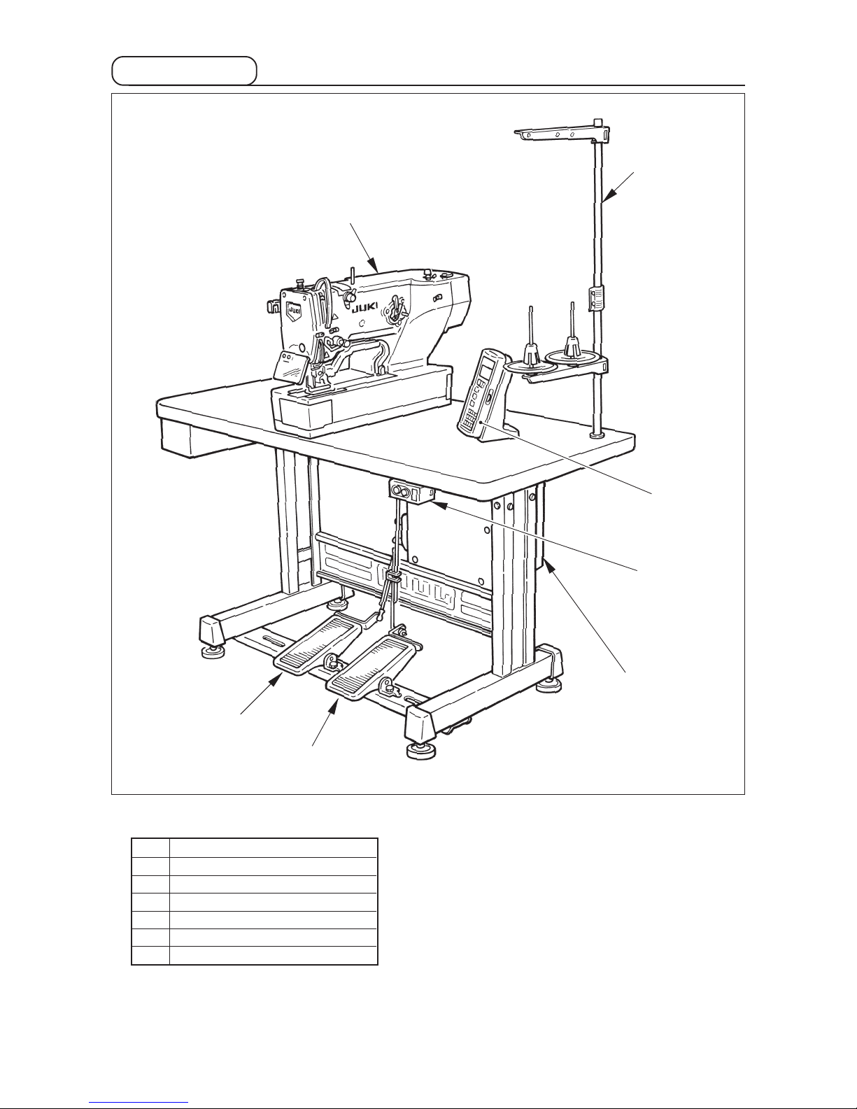
4. Configuration ........................................................................................................................................ 3
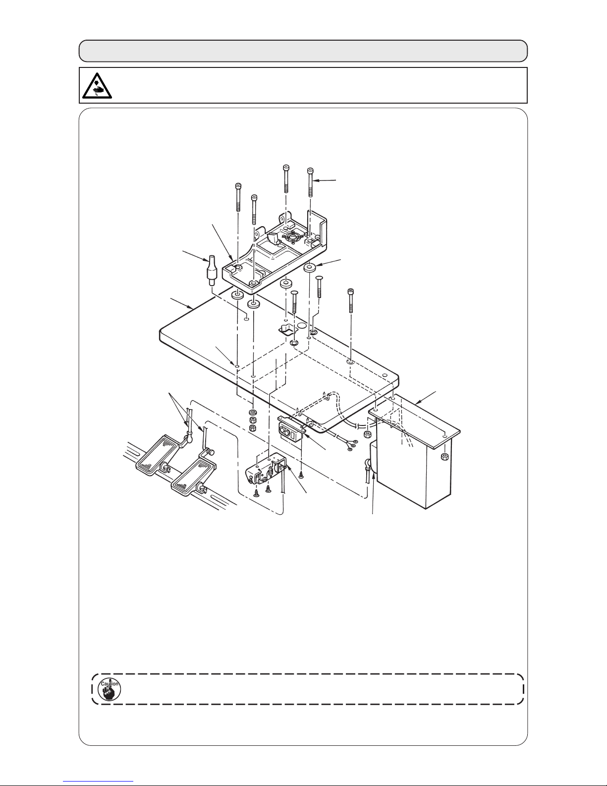
蠱. INSTALLATION ............................................................................................................. 4
蠶. PREPARATION BEFORE OPERATION ..................................................................... 12
1. Lubrioation .......................................................................................................................................... 12
2. Inserting the needle ............................................................................................................................ 12
3. Threading the needle-thread .............................................................................................................. 13
4. Threading the bobbin case ................................................................................................................ 13
5. Adjusting the bobbin thread tension ................................................................................................ 14
6. Installation of bobbin case .................................................................................................................14
7. Installing the knife .............................................................................................................................. 15
蠹. OPERATION OF THE SEWING MACHINE ................................................................. 16
1. Explanation of the operation panel switch ....................................................................................... 16
2. Basic operation of the sewing machine ........................................................................................... 18
3. How to use the pedal .......................................................................................................................... 18
4. Input of the presser type .................................................................................................................... 20
5. Performing pattern selection ............................................................................................................. 21
6. Changing needle thread tension ....................................................................................................... 22
7. Performing re-sewing ......................................................................................................................... 23
8. Winding bobbin thread .......................................................................................................................24
9. Using the counter ...............................................................................................................................25
10. Using the initial value pattern ............................................................................................................26
11. Changing sewing data ........................................................................................................................27
12. Method of setting sewing data with/without edit ............................................................................. 28
13. Sewing data list ................................................................................................................................... 29
14. Copying sewing pattern ..................................................................................................................... 35
15. Using pattern register key.................................................................................................................. 36
16. Using parameter register key ............................................................................................................ 37
17. Performing continuous stitching ....................................................................................................... 38
18. Performing cycle stitching .................................................................................................................40
19. Explanation of plural motions of knife.............................................................................................. 42
20. Method of changing memory switch data ........................................................................................43
21. Memory switch data list ..................................................................................................................... 44
蠧. MAINTENANCE .......................................................................................................... 48
1. Adjusting the needle-to-hook relation .............................................................................................. 48
2. Adjusting the needle thread trimmer ................................................................................................ 49
3. Adjusting the presser bar pressure .................................................................................................. 50
4. Adjustment of the bobbin presser unit .............................................................................................50
5. Thread tension .................................................................................................................................... 52
6. Cleaning the filter ................................................................................................................................ 52
7. Replacing the fuse ..............................................................................................................................52
蠻. GAUGE COMPONENTS ............................................................................................. 53
1. Cloth cutting knife ..............................................................................................................................53
2. Throat plate ......................................................................................................................................... 53
3. Presser ................................................................................................................................................. 53
衄. ERROR CODE LIST .................................................................................................... 54
衂. TROUBLES AND CORRECTIVE MEASURES ........................................................... 57
衒. DRAWING OF THE TABLE ......................................................................................... 59
衙. INITIAL VALUE DATA FOR EACH SHAPE TABLE .................................................... 60

−1 −
1.
IMPORTANT SAFETY INSTRUCTIONS
1) Never operate the machine unless the oiling tank has been properly lubricated.
2) Be sure to remove any dust from the hook or bobbin thread cutting knife section at the end of the day,
and check the amount of oil remaining.
3) Be sure to return the activating pedal to the home position after the machine has started to run.
4) A safety switch is installed so that this sewing machine can not be operated in the state that the machine
head is tilted. When operating this sewing machine, turn the power switch ON after setting the sewing
machine to the bed base properly.
2. SPECIFICATIONS
1. Subclass
Computer-controlled, high-speed, lockstitch buttonholing machine, LBH-1790, has the subclass machines below.
Subclass
Major
application
Buttonholing
size
S
Buttonholing of cloth
such as men’s shirts,
blouses, work uniforms,
ladies' wear, etc.
2. Specifications
Sewing speed
Needle
Hook
Needle rocking drive
method
Feed drive method
Presser lifting drive
method
Lift of presser foot
Cloth cutting knife
drive method
Standard sewing
shape
Number of patterns
stored in memory
Motor used
Noise
Standard speed : 3,600 rpm (Max. : 4,200 rpm) (Max. : 3,300 rpm when dry hook is used)
DPX5 #11J to #14J
DP type full-rotary hook
Drive by stepping motor
14 mm (Optional setting available) Max. : 17 mm (At the time of needle up by reverse run)
By double-acting solenoid drive
30 kinds
99 patterns
Single phase 220/230/240 V, 3-phase 200 to 240 V, 1000 VA
Workplace-related noise at sewing speed
n = 4,000 min–1 : LPA ≦83 dB(A)
Noise measurement according to DIN 45635-48-A-1.
Standard : Max. 5 mm
Special type part : Max. 10 mm
Buttonholing sewing length
Standard : Max. 41 mm
Special type part : Max. 120 mm
Knife size used :
6.4 to 31.8 mm (1/4' to 1-1/4')
K
Buttonholing of knits
such as knitted
underwear, sweaters,
cardigans, jersey, etc.

−2 −
3. Standard sewing shape list
(1) Square type (2) Round type (3) Radial square type (4) Radial type (5) Radial straight bar-
tacking type
(6) Radial taper bar-tacking
type
(7) Eyelet square type (8) Eyelet radial type (9) Eyelet straight bar-
tacking type
(10) Eyelet taper bar-
tacking type (11) Semilunar type (12) Round square type
(13) Semilunar square
type
(14) Semilunar straight
bar-tacking type
(15) Semilunar taper bar-
tacking type
(16) Eyelet semilunar
type (17) Eyelet round type (18) Square radial type
(19) Square semilunar
type (20) Square round type (21) Square straight bar-
tacking type
(22) Square taper bar-
tacking type
(23) Radial semilunar
type (24) Radial round type
(25) Semilunar radial type (26) Semilunar round
type (27) Bar-tacking (28) Bar-tacking, right cut (29) Bar-tacking, left cut (30) Bar-tacking, center cut
PANEL
DISPLAY
PANEL
DISPLAY
PANEL
DISPLAY
PANEL
DISPLAY
PANEL
DISPLAY
PANEL
DISPLAY
PANEL
DISPLAY
PANEL
DISPLAY
PANEL
DISPLAY
PANEL
DISPLAY
PANEL
DISPLAY
PANEL
DISPLAY
PANEL
DISPLAY
PANEL
DISPLAY
PANEL
DISPLAY
PANEL
DISPLAY
PANEL
DISPLAY
PANEL
DISPLAY
PANEL
DISPLAY
PANEL
DISPLAY
PANEL
DISPLAY
PANEL
DISPLAY
PANEL
DISPLAY
PANEL
DISPLAY
PANEL
DISPLAY
PANEL
DISPLAY
PANEL
DISPLAY
PANEL
DISPLAY
PANEL
DISPLAY
PANEL
DISPLAY

−3 −
4. Configuration
LBH-1790consists of the following components.
qPower ON/OFF switch
wMachine head (LBH-1790)
eOperation panel
rControl box (MC-601)
tPresser lifting pedal
yStarting pedal
uThread stand device
q
w
t
r
e
y
u

−4 −
(1) Set-up of the table
3. INSTALLATION
WARNING :
To prevent possible accidents caused by the fall of the sewing machine, perform the work by two persons
or more when the machine is moved.
1) Securely install control box wand power switch eon table q.
2) Securely fix the respective power cables of power switch e.
3) Pass four bed base fixed screws !1 through bed base r.
4) Set rubber cushions tto holes y(4 places) for fixing bed base and fix bed base r.
5) Fix head support bar uon table q.
6) After placing the sewing machine main unit on bed base r, connect pedal (right side) to pedal switch
o, and pedal (left side) to pedal sensor !0 respectively with connecting rods iwhich have been
supplied as accessories.
Adjust the positions of the pedals so that connecting rods iand control box wdo not
come in contact with each other.
q
w
t
r
e
y
u
i
!0
!1
o

−5 −
(2) Connecting the power source cord
• Voltage specifications
Power source specifications are indicated on the
voltage indication seal. (3-phase type only)
For other type machines, power source specifications
are indicated on the voltage caution seal and the
rating label.
Connect the cord in accordance with the
specifications.
Table
Brown Brown
Brown
Light blue Light blue
Light
blue
Green/Yellow Green/
Yellow
Control box
Green/Yellow
Plug
Power source cord
Power switch
GND
AC200 V
AC220 V
AC230 V
AC240 V
Voltage indication seal (3-phase type only)
• Connecting single phase 200V, 220V, 230V and 240V
Table
Red
Black
Green /
Yellow
White
Control box
Power source cord
Plug
Power switch
GND
AC200 V
AC220 V
AC240 V
• Connecting three phase 200V, 220V and 240V
Green/Yellow
Voltage caution seal
Red
White
Black
Green /
Yellow
Red
Black
White
Rating label
1. Never use under the wrong voltage and phase.
2. When changing the voltage, refer to the item of "Changing the voltage of 100 /
200V".

−6 −
(3) Changing the voltage of 100 / 200V
WARNING :
To prevent personal injuries caused by electric shock hazards or abrupt start of the sewing
machine, carry out the work after turning OFF the power switch and a lapse of 5 minutes or
more. To prevent accidents caused by unaccustomed work or electric shock, request the electric
expert or engineer of our dealers when adjusting the electrical components.
Changing procedure of the changeover connector
1. Turn OFF the power source with the power
switch after confirming that the sewing machine
has stopped.
2. Draw out the power cord from the power plug
socket after confirming that the power switch is
turned OFF. Then wait for five minutes or more.
3. Remove the front cover.
4. Remove four screws fixing the rear cover of the
control box and slowly open the rear cover.
A. In case of using with 3-phase 200V to 240V
•Changing the changeover connector
Connect to 200V the 100/200V changeover
connector of FLT p.c.b. 1located on the side
of the Box Side of the control box.
•Connect the crimp style terminal of AC input cord
to the power plug as shown in the figure.
B. In case of using with single phase 100V to 120V
•Changing the changeover connector
Connect to 100V the 100/200V changeover
connector of FLT p.c.b. 1located on the side
of the Box Side of the control box.
•Connect the crimp style terminal of AC input cord
to the power plug as shown in the figure.
(Caution) Securely perform the insulation
treatment to the red terminal which
is not used with insulation tape or
the like.
(When the insulation is insufficient,
there is a danger of electric shock or
leakage current.)
C. In case of using with single phase 200V to 240V
•Changing the changeover connector
Connect to 200V the 100/200V changeover
connector of FLT p.c.b. 1located on the side
of the Box Side of the control box.
•Connect the crimp style terminal of AC input cord
to the power plug as shown in the figure.
(Caution) Securely perform the insulation
treatment to the red terminal which is
not used with insulation tape or the
like.
(When the insulation is insufficient,
there is a danger of electric shock or
leakage current.)
5. Check that the change has been performed without
fail before closing the rear cover.
6. Be careful that the cord is not pinched between
the rear cover and the control box main unit. Close
the rear cover while pressing the lower side of rear
cover, and tighten four screws.
It is adaptable to the voltage of single phase 100V to 120V/3-phase 200V to 240V by changing the
voltage changeover connector mounted on FLT p.c.b.
(Caution) When the changing procedure is wrong, the control box will be broken. So, be very
careful.
1
GREEN/
YELLOW
(Plug side)
WHITE
BLACK
RED
WHITE
BLACK
RED
GREEN/
YELLOW
GREEN/
YELLOW
(Plug side)
WHITE
BLACK
RED
WHITE
BLACK
RED
GREEN/
YELLOW
(Plug side)
GREEN/
YELLOW
GREEN/
YELLOW
A
B
C
WHITE
BLACK
RED
WHITE
BLACK
RED

−7 −
(4) Installing the sewing machine main unit
1) Place hinge plates qand shaft bearings w-1
(rubber) and w-2 (metal) in two places on the
head base and fix the hinge plates to the machine
head with setscrews ein two places.
When the rubber hinge and metal fitting
hinge are installed in reverse order, it is
dangerous since the sewing machine
shakes when it is tilted. So, be careful.
WARNING :
To prevent possible accidents caused by the
fall of the sewing machine, perform the work
by two persons or more when the machine
is moved.
q
e
w-1 (rubber)
w-2
(metal)
(5) Tilting the sewing machine head
When tilting the sewing machine head, tilt quietly the
sewing machine until head support bar qcomes in
contact with it.
1. Make sure that sewing machine head
support bar qis placed on the table
before tilting the sewing machine.
2. To protect fall-down, be sure to tilt the
sewing machine in a level place.
WARNING :
When tilting/raising the sewing machine head, perform the work so as not to allow your fingers to
be caught in the machine. In addition, to avoid possible accidents caused by abrupt start of the
machine, turn OFF the power to the machine before starting the work.
q

−8 −
(6) Connecting the safety switch connector
1) Connect safety switch connector q
with connector wlocated on the
machine head side.
(7) Installing the hook oil shield plate
Install hook oil shield plate qonto bed base ewith
setscrew w.
Fix the sewing machine so that it does
not come in contact with hook oil shield
plate qwhen raising/tilting the sewing
machine.
q
w
e
(8) Installing the operation panel
Fix operation panel attaching plate qon the table
with woodscrew wand pass the cable through hole
ein the table.
q
w
e
q
w
Cord clamp

−9 −
(9) Connecting the cords
Perform the connection of the cords as shown in the figure below.
Electric bobbin winding device (optional)
1) Pass 4 cords (CN38, 39, 41, and 42) connecting
to the right side among the cords connecting to
MAIN circuit board through cord clamp A as shown
in the figure, and connect them to the respective
connectors. Connect CN37 to the connector
without passing through cord clamp A.
In addition, when using the electric bobbin winding
device (optional), similarly pass the cord of the
bobbin winding device through the cord clamp and
connect it to CN44.
2) Directly connect the cord from the operation panel
connecting to the left side of MAIN circuit board
to CN34.
3) Connect the cords connecting to SDC circuit board
directly to CN14 and CN16.
4) Fix the earth wire with the setscrew q.
MAIN circuit
board
Sewing machine head
Operation panel
CN44
CN34
CN41
CN39
CN42
CN38
CN37
CN16
CN14
CN44
CN34
CN41
CN39
CN42
CN38
CN37
CN16 CN14
Cord
clamp A
CN16
CN14
q
SDC circuit
board
SDC circuit board

−10 −
(11) Installing the eye protection cover
Be sure to install and use eye protection cover qand use the sewing machine.
WARNING :
Be sure to attach this cover to protect the eyes from the disperse of needle breakage.
When placed longitudinally When placed horizontally
(10) Managing the cord
1) Slowly tilting the sewing machine, check that the cords are not forcibly pulled.
2) Fix the cords with cord setting plate qas shown in the figure.
When you tilt the sewing machine, make sure that the sewing machine head support
bar wis placed on the table.
Operator
Operator
w
q
q
q

−11 −
(12) Fixing the temporary stop switch
The temporary stop switch has been in the state as shown in figure A at the time of delivery.
Loosen setscrew qand set the switch in the state as shown in figure B, and fix it with setscrew qtogether
with setscrew wsupplied with the machine.
q
q
w
A
B
\
(13) Thread guide rod
Securely fit the thread guide rod so that two side holes
in the thread guide rod face the thread guide.
Thread guide rod
(14) Installing the thread stand
1) Assemble the thread stand, and set it in the hole
in the top right corner of the machine table.
2) Tighten locknut qto fix the thread stand.
3) When ceiling wiring is possible, pass the power
cable through spool rest rod w.
q
w

−12 −
4. PREPARATION BEFORE OPERATION
1. Lubrioation
Hold needle with its recessed part facing toward the operator side A,
insert the needle fully into the needle clamping hole, and tighten needle
setscrew q. Use a DPx5-(#11J, #14J).
When attaching the needle, turn OFF the power to the
motor.
2. Inserting the needle
WARNING :
To protect against possible personal injury due to abrupt start of the machine, be sure to start the
following work after turning the power off and ascertaining that the motor is at rest.
1) Lubricating oil to oiling tank
○Fill the oiling tank with New Defrix Oil No.1 up to the level indicated by “MAX” q.
2) Adjusting the lubrication for the sewing hook
○Adjust the amount of oil supplied to the sewing hook by loosening lock nut wand turning oil amount
adjusting screw e.
○Amount of supplied oil is reduced when turning the screws eclockwise.
○Fix the screw with lock nut wafter adjusting the lubrication for the sewing hook.
○When you first operate your sewing machine after set-up or after an extended period of disuse, remove
the bobbin case and apply a few drops of oil to the hook race. In addition, apply a few drops oil from oiling
hole rin hook driving shaft front metal tto soak the inside felt in oil.
WARNING :
To protect against possible personal injury due to abrupt start of the machine, be sure to start the
following work after turning the power off and ascertaining that the motor is at rest.
q
A
Detailed diagram of oil amount adjusting section
Oil pipe
Decrease
Oil amount
Increase
w
e
q
t
r
we

−13 −
Rotating direction of bobbin and threading
1) Fit the bobbin so that it rotates in the direction of the arrow.
2) Pass the thread through thread slit q, then through under the tension spring w, again through thread
slit e, and pull the thread from r.
3) Threading at rfor purl stitching is different from that for whip stitching. So, be careful.
4. Threading the bobbin case
3. Threading the needle-thread
Pass the needle thread in the order qto !2 as shown in the figures.
The threading can be done easily by using the needle threader supplied with the machine.
Change the thread guide threading method according to the thread to be used.
Synthetic filament thread
Cotton thread, spun thread
Whip stitchPurl stitch
q
Bobbin case
Bobbin
r
w
e
r
WARNING :
To protect against possible personal injury due to abrupt start of the machine, be sure to start the
following work after turning the power off and ascertaining that the motor is at rest.
q
w
t
r
e
y
u
i
o
!0
!1
!2

−14 −
5. Adjusting the bobbin thread tension
q
w
6. Installation of bobbin case
1) Lift up and hold bobbin case latch lever between
two fingers.
2) Push the bobbin case into the hook so that it is
supported by the hook shaft qand then snap in
the latch lever.
Press the bobbin case until the predetermined
position is reached, and it will click.
1. If the bobbin case is out of the
predetermined position, it can jump
out from the hook to cause the needle
thread to tangle on the hook shaft.
Check to be sure that the bobbin case
is properly installed in the correct
position.
2. There is a difference in the shape of
bobbin case between the standard
hook and the dry one. They have
nothing in common with each other.
Adjust the bobbin thread tension as given below when the bobbin thread is pulled up at the position where
thread slit qof bobbin case comes up.
Turning tension adjust screw wclockwise will increase bobbin thread tension, and turning it counterclockwise
will decrease the tension.
Adjust the bobbin thread tension to lower for synthetic filament thread, and to higher for spun thread. The
thread tension is higher by approximately 0.05N when the bobbin case is set to the hook since idle-prevention
spring is provided.
When bobbin thread tension is adjusted, check the needle thread tension setting of the
memory switch. (See P.44.)
Purl stitch
Whip stitch
0.05 to 0.15N
0.15 to 0.3N
To such an extent that bobbin case quietly comes down when holding
thread end coming from bobbin case and shaking it quietly up and
down.
To such an extent that bobbin case barely comes down when holding
thread end coming from bobbin case and shaking it somewhat
strongly.
WARNING :
To protect against possible personal injury due to abrupt start of the machine, be sure to start the
following work after turning the power off and ascertaining that the motor is at rest.
q

−15 −
7. Installing the knife
Inch →mm CONVERSION TABLE
When the cloth cutting knife you have is indicated in
inch, set the cloth cutting length (knife size) in mm using
the inch →mm conversion table. (See P.29.)
Knife size Indication of mm
1/4 6.40
3/8 9.50
7/16 11.10
1/2 12.70
9/16 14.30
5/8 15.90
11/16 17.50
3/4 19.10
13/16 20.60
7/8 22.20
125.40
1 1/8 28.60
1 1/4 31.80
1 3/8 34.90
1 1/2 38.10
When replacing the knife with a new one, perform as
follows.
1) Knife qcan be easily removed together with the
washer when removing knife retaining screw w.
2) Adjust so that the knife, when lowered the knife
bar by hand, is spaced 1 to 2 mm away from the
top surface of the throat plate as illustrated in the
sketch. Then, be sure to place the washer and
tighten the knife retaining screw.
q
w
1 to 2 mm
WARNING :
To protect against possible personal injury due to abrupt start of the machine, be sure to start the
following work after turning the power off and ascertaining that the motor is at rest.
Other manuals for LBH-1790 Series
5
Table of contents
Other JUKI Sewing Machine manuals

JUKI
JUKI MO-735 User manual

JUKI
JUKI LK-1900B series Quick start guide

JUKI
JUKI Exceed F-600 User manual

JUKI
JUKI DDL-5550-7 User manual

JUKI
JUKI DDL-5550N User manual

JUKI
JUKI PLK-J4040R User manual

JUKI
JUKI MF-7000 Series Quick start guide

JUKI
JUKI DNU-1541S User manual

JUKI
JUKI LH-4128 User manual

JUKI
JUKI HZL-E70 User manual

JUKI
JUKI PLK-G4030R User manual

JUKI
JUKI MF-7900D/UT59 User manual

JUKI
JUKI DNU-1541 Quick start guide

JUKI
JUKI MO-735 User manual

JUKI
JUKI S057 User manual

JUKI
JUKI DU-141H-4 User manual

JUKI
JUKI AMS-210EN Series Quick start guide

JUKI
JUKI LK-1850 Series User manual

JUKI
JUKI HZL-350Z series User manual

JUKI
JUKI NZ-120 User manual