Chang Rui Technology FLW-717C User manual
Document Type:Maintenance Issue
Confidentiality:Secrecy
FLW-717C
Product Manual
File Status:
[√] Draft
[ ] Released
[ ] Modifying
Document
identification:
current version:
V2.2
Author:
Lvjun Hao
Production unit:
Shenzhen, Chang Rui Technology Co., Ltd.
Completion Date:
Audit:
Document revision history table
Release / Status
Modifier
Change the time
Modifications
V1.0
Lvjun Hao
2013-12-30
The initial content
V1.5
Chen Mei
2015-7-23
V2.2
Du Wen Peng
2017-9-22
Update the control software
Remove Hardware Address

FLW-717C Product Manual
Shenzhen City Chang Rui Technology Co., Ltd
Copyright and Licensing Shenzhen, Chang Rui Technology Co., Ltd.
All rights reserved. Unless allowed under copyright laws. Otherwise, in the case without prior
written permission is prohibited reproduction, adaptation, or translation of this book.
Associated with this user manual have the following powers: A: To print the manual to get their hard
copy for personal, internal, or corporate purposes, and not for sale, resale or distribution purposes; B:
this manual only as Shenzhen Chang Rui Technology Co., maintenance and use self-service products.
Document declaration
The information contained herein is subject to change without notice. The Company does not
make any guarantees in this book. The book contained an error by the company for its supply,
performance or use of the incidental or consequential damages shall not be liable.

FLW-717C Product Manual
Shenzhen City Chang Rui Technology Co., Ltd
TABLE OF CONTENTS
CHAPTER 1:FEATURES ENVIRONMENTAL INDICATORS.................................................................................................................... 5
1.1 FEATURES.................................................................................................................................................................................... 6
1.2 FEATURE......................................................................................................................................................................................6
1.2.1 Support Framework features
.............................................................................................................................................6
1.2.2 thermostatically controlled fan
.........................................................................................................................................7
1.2.3 Built-random code soft address set…………………………………………………………………………………………………………………………… 7
1.2.4 boot LOGO stitching.............................................................................................................................................................7
1.2.5 USB power upgrades........................................................................................................................................................... 7
1.2.6 point display function.......................................................................................................................................................... 8
1.3 SPLICING UNITBLOCK DIAGRAM.......................................................................................................................................................... 8
1.4 SYSTEM STRUCTURE PRINCIPLE............................................................................................................................................................ 9
1.5 BLOCK DIAGRAM OF THE SCREEN WALL MOSAIC (2X2).........................................................................................................................10
1.6 HARDWARE ADDRESS SETTING......................................................................................................................... 错误!未定义书签。
1.7 DIP CORRESPONDENCE TABLE.......................................................................................................................... 错误!未定义书签。
1.8 TROUBLESHOOTING........................................................................................................................................................................ 10
1.9 PERFORMANCE..............................................................................................................................................................................11
CHAPTER 2 :PHYSICAL MAP................................................................................................................................................................ 12
CHAPTER 3: SIZE DEFINITIONS............................................................................................................................................................15
CHAPTER 4: SETUP POSTER.................................................................................................................................................................17
4.1 INSTALLATION:............................................................................................................................................................................18
CHAPTER 5: BURNING SOFTWARE..................................................................................................................................................... 19
5.1 SOFTWARE UPGRADE GUIDE............................................................................................................................................................19
5.2 USB UPGRADE STEPS...................................................................................................................................................................... 19
5.3 ISP UPGRADE................................................................................................................................................................................20
5.4 COMMON FAULT ANALYSIS:.............................................................................................................................................................21
CHAPTER 6: PC SOFTWARE FOR USE.................................................................................................................................................. 22
6.1 SYSTEM OPERATING ENVIRONMENT:.................................................................................................................................................. 22
6.2 START SYSTEMS:............................................................................................................................................................................. 22
6.3 HOW TO GET STARTED.....................................................................................................................................................................23
6.4 SYSTEM CONFIGURATION.................................................................................................................................................................25
6.5 MATRIX CONFIGURATIONS:...............................................................................................................................................................26
6.6 SPLICING OPERATION...................................................................................................................................................................... 26
6.7 OTHER FEATURES:..........................................................................................................................................................................28
6.7.1 Image................................................................................................................................................................................. 30
6.7.2 Color...................................................................................................................................................................................30
6.7.3 Geometry........................................................................................................................................................................... 32
6.7.4 front-end brightness gain.................................................................................................................................................. 32

FLW-717C Product Manual
Shenzhen City Chang Rui Technology Co., Ltd
6.7.5 front-end brightness compensation...................................................................................................................................32
6.7.6 User Management.............................................................................................................................................................33
6.7.7 Additional Ribbon.............................................................................................................................................................. 33
6.8 SPECIAL ADDITIONAL FUNCTIONAL AREA (PASSWORD REQUIRED BACKGROUND):........................................................................................34
CHAPTER 7: SAFETY PRECAUTIONS.................................................................................................................................................... 39
7.1.1 Please read this manual;................................................................................................................................................ 39
7.1.2 retain this manual for future use;...................................................................................................................................39
7.1.3 before the device is turned inside the device should check whether there is abnormal……………………………………………..47
7.1.4 Power on the device before the power supply voltage to be determined,which is exactly adjusted to
220V….................47
7.1.5 careful not to step on the power cord, do not cover the power cord…………………………………………………………………………47
7.1.6 before any part of the equipment to make changes, first off…………………………………………………………………………………….47
7.1.7 If the following occurs, please let service personnel;..................................................................................................... 40
7.1.8 The power cord or plug is damaged;.............................................................................................................................. 40
7.1.9 device does not work;..................................................................................................................................................... 40
7.1.10 equipment damage;..................................................................................................................................................... 40
7.1.11 equipment has obvious cracks......................................................................................................................................40

FLW-717C Product Manual
Shenzhen City Chang Rui Technology Co., Ltd
Product Introduction
FLW-717C is designed for large-screen LCD splicing system designed splice point screen
is its unique modular design, integrates a variety of signal decoding unit, multi-screen
mosaic processing unit, LCD driver unit, power supply units, etc. parts. Flexible and easy
to form a large-screen LCD display wall system.
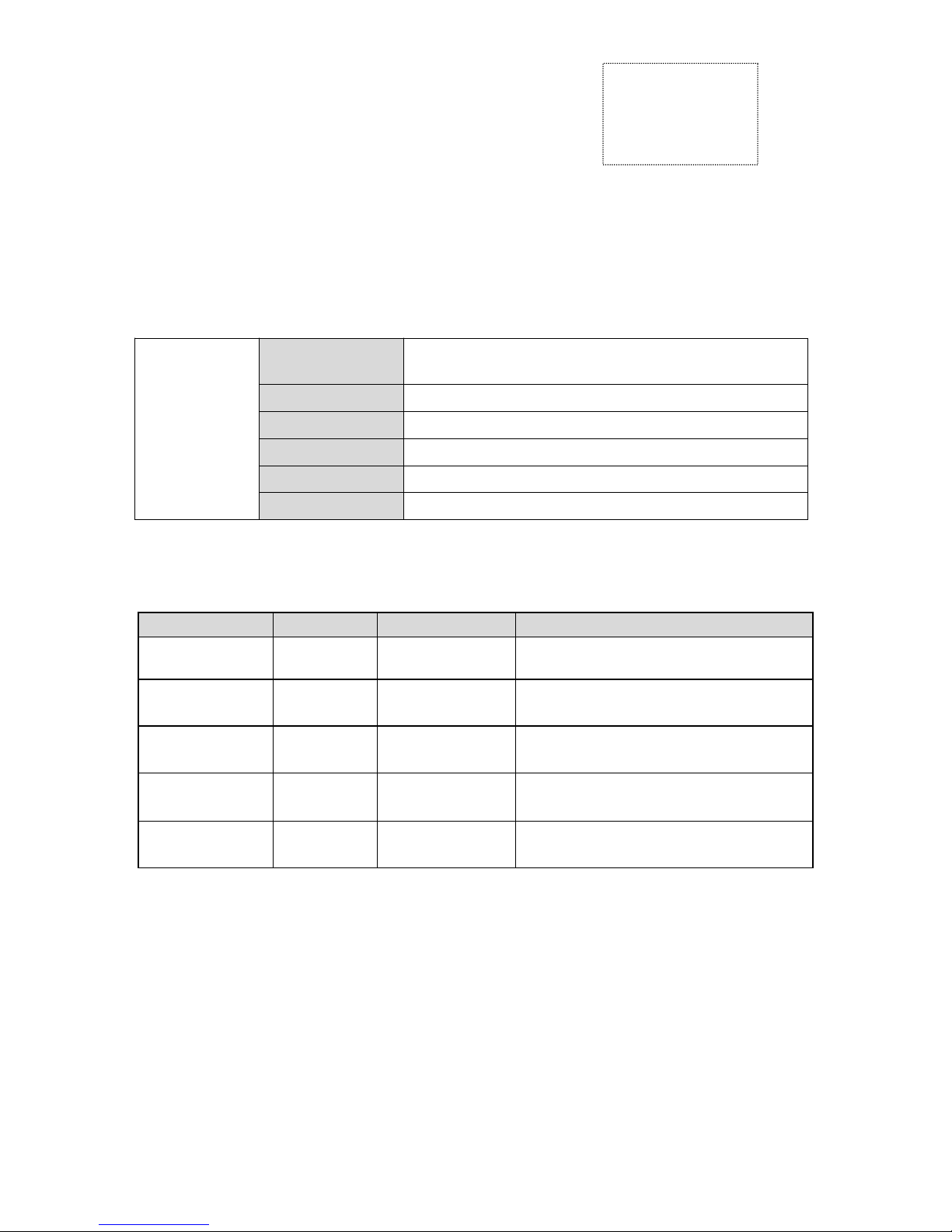
Chapter 1:Features Environmental Indicators
ID
Enter
1channel hardware
DIP switch
Used to enter the ranks of the corresponding hardware address, from 1-8 1-4 respectively
represent the row address 5-8 for column address, maximum 15 lines X15 ranks of
support columns.
Enter
1 channel CVBS
Transposon BNC interface, support PAL / NTSC all standard, all the way to ring out.
1 channel VGA
Support VGA signal 1920X1080 60Hz or less most of 60Hz resolution.
1 channel DVI
1920X1080 60Hz DVI signal support most of the following 60Hz resolution.
1 channel HDMI
Support the full resolution HDMI 1080P60Hz signal less.
YPbPr/AV2/AV3
There is a way for external CN20 transposon YPBPR or RGB HS VS, two AV signal
AV2, AV3 or all the way SV signal.
Export
Backlit
Two 13pin backlight and backlight control signal DC power output.
LVDS
Support for single and double road LVDS, the highest cocoa support WUXGA
(1920X1080) screen.
Engineering SystemSoftware
717C splice box V1.0.0.6, RS232 interface control (a way forward, 2-way loop out)
Operating temperature
0~70℃
Working humidity
5~95%RH
Power AC voltage
100-240V/50,60Hz
Power consumption
Maximum 300W, according to different screen models
Chassis Size
307×282×53.8(mm)

FLW-717C Product Manual
Shenzhen City Chang Rui Technology Co., Ltd
1.1 Features
•Full hardware architecture, no CPU and operating system;
•Multi-bus parallel processing, handling and powerful;
•Start-up time of less than 8 seconds, start quickly;
•No risk of virus infection, good security;
•Integrated multi-channel video signal source types: DVI, HDMI, composite video, VGA;
•Composite video loop out;
•Embedded 3D video bright separation circuit unit;
•Embedded 3D progressive normalization process and frame rate conversion circuit unit;
•Embedded 3D digital signal noise reduction unit;
•Unit supports drive to 1920X1080 LCD screen;
• RS232 serial remote control; each unit supports two-way RS232 ring out;
•Can continue to work 24 hours a day;
•Easy to operate, with FTM_CONTROL software can flexibly operate the system;
•It can open the underlying communication protocol,user-friendly and flexible
usethird-party control system;
•Or prepare their own software system constructed large-screen project.
1.2 Feature
1.2.1 Support Framework features
All pictures built-in frame compensation function can adjust the screen to window.

FLW-717C Product Manual
Shenzhen City Chang Rui Technology Co., Ltd
1.2.2 thermostatically controlled fan
Built-in temperature controlled fan starts running, the fan can be adjusted according
to the actual operating temperature, in order to ensure effective fan life.
1.2.3 Built-random code soft address set
Built-in random number generator that can generate a random code by Rs232
FLW-717C communication control box, this random code for each machine varies and can
be set soft random code generated by a unique address, which is soft address instead of
hardware address, convenient construction site.
1.2.4 boot LOGO stitching
Power LOGO stitching facilitate customer according to their own needs, to configure
the LOGO display, so you can achieve better publicity display.
1.2.5 USB power upgrades
Division I use USB to RJ45 adapter cable, and then you can easily upgrade software
at the construction site, the use of adapter cable and a U disk, you can splice a project officer
FLW-717C Product Manual
Shenzhen City Chang Rui Technology Co., Ltd
for the entire system FLW-717C module to do all the upgrades, as long as the U after the
disk memory into the software to be upgraded, use cable to connect the U disk connected to
the corresponding FLW-717C machine, and then re-AC, FLW-717C box detected
automatically after the software upgrade into the upgrade module, the corresponding power
indicator light flashes prompted to upgrade, lights do not flash until the upgrade is complete.
1.2.6 point display function
With this feature, you can easily clear view DVI, VGA document under which can achieve
high resolution, making documents more clear and bright.
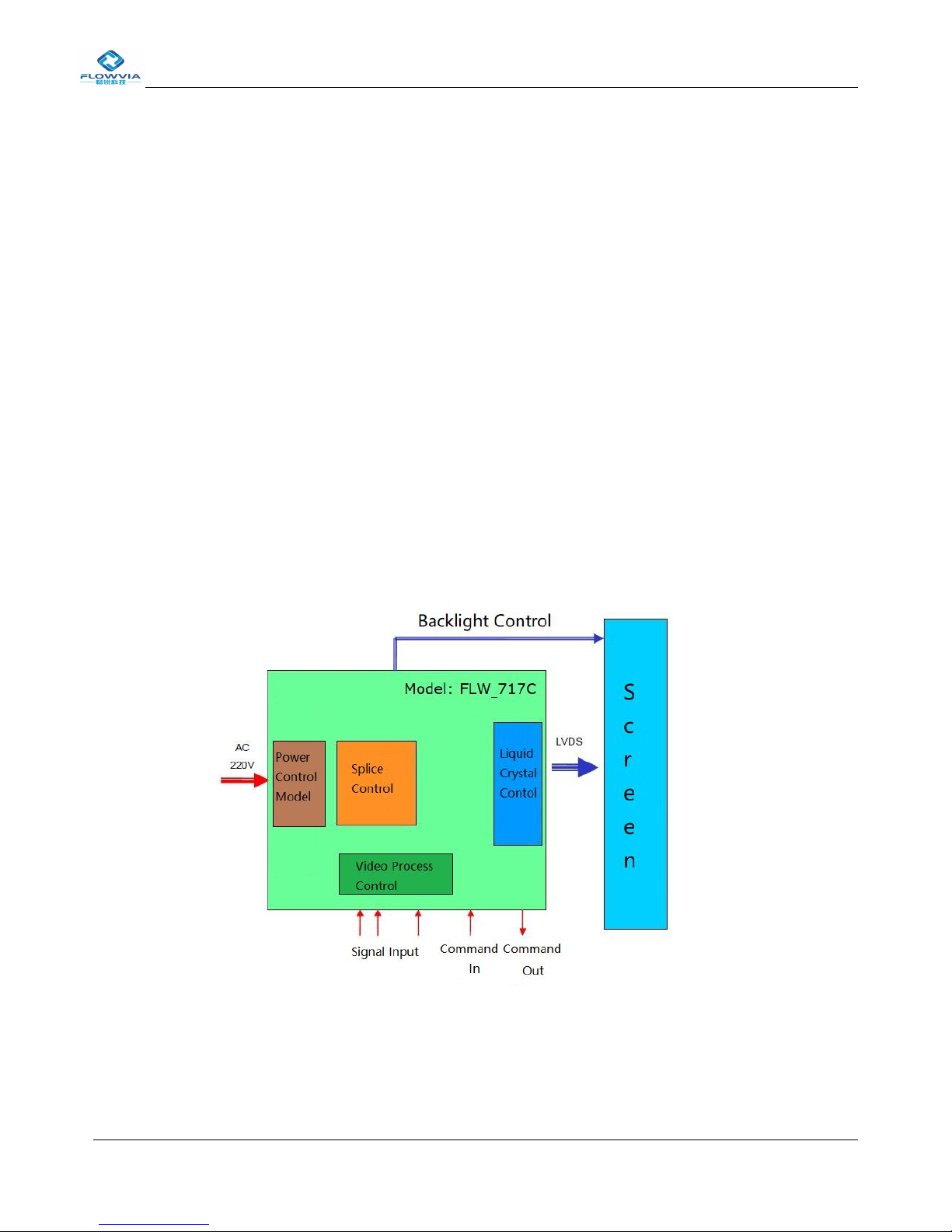
1.3 Splicing unitblock diagram
Embedded processing systems, each unit has its own processing module and power
module, and via serial port communication between units.

FLW-717C Product Manual
Shenzhen City Chang Rui Technology Co., Ltd
1.4 System structure principle

FLW-717C Product Manual
Shenzhen City Chang Rui Technology Co., Ltd
1.5 Block diagram of the screen wall mosaic (2X2)
1.8 Troubleshooting
When the product fails, turn off the power immediately, please do not attempt to disassemble the unit for
repair, the product may cause further damage. The following steps can be ruled out, still can not be solved,
please contact your local dealer or qualified service personnel. For the user to repair the product, not the
company's warranty.
It is like
Approach
Does not boot (power
light is off)
1、Check that the power cord is damaged;
2、Whether the power is access to electricity;
3、Make sure the power is turned on;
4、Is the power switch is damaged;
5:It is blown fuse。
All splicing unit
uncontrolled
1、Check the stitching software port settings are correct;
2、check the serial cable is damaged, and whether the PC
interface products and good contact;
3、PC's serial port to check whether there is a problem, you can
replace the PC test;

FLW-717C Product Manual
Shenzhen City Chang Rui Technology Co., Ltd
4、Address splicing unit is set correctly, see the address settings.
Uncontrolled individual
splicing unit
1、Check the address of the device settings are correct.
2、Individual control of the device was successful.
Single or multiple
devices VGA / DVI
no input
1、Check unit board and the signal source end of the interface is a
good contact;
2、Replacing a VGA or DVI cable test;
3、The device is set in the input status;
4、The input signal exceeds the input range of the product;
5、When the DVI input, make sure there is caught DDC, and
there is output.
1.9 Performance
Operating temperature:-15℃-65℃
Working humidity:Relative humidity less than 95%
Power consumption:≤300W,Screen type and size of the
voltage:95V AC-250V AC
Composite video format:PAL、NTSC、SECAM
Composite video Peak:1Vp-p
control method:RS-232(RJ45)
VGA input:WUXGA(1920*1080)
DVI input:WUXGA(1920*1080)
Screen resolution support:WUXGA(1920*1080),Dual 10bit
Temperature-controlled fan:Automatic control
FLW-717C Product Manual
Shenzhen City Chang Rui Technology Co., Ltd
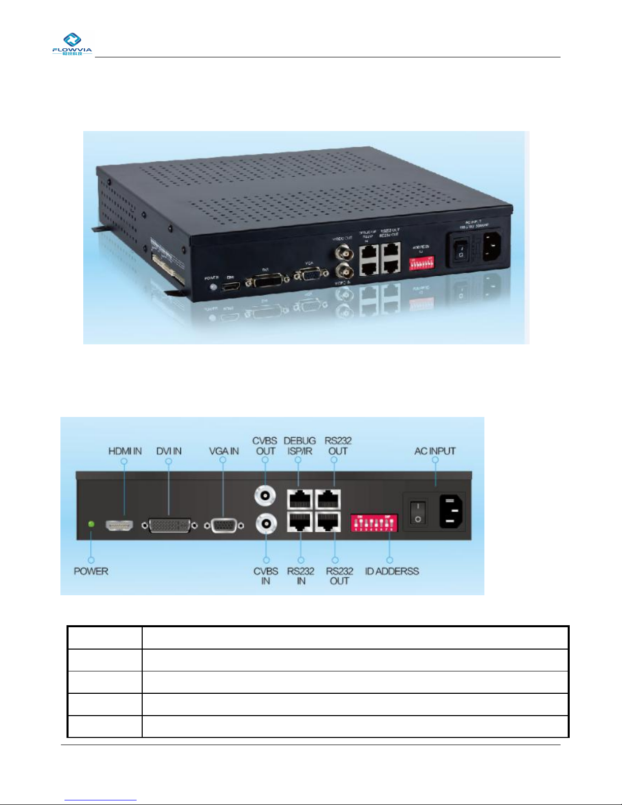
Chapter 2 :Physical map
This is M59W V1.5 board assembly FLW-717C board pictures taken.
Interface Definition
serial number
Explanation
POWER
Power indicator light, orange standby, green jobs;
HDMI IN
HDMI input signal interface;
DVI IN
DVI input signal interface;
VGA IN
VGA input signal interface;

FLW-717C Product Manual
Shenzhen City Chang Rui Technology Co., Ltd
CVBS OUT
CVBS / Composite video signal interface loop out (interface type BNC);
DEBUG
ISR/IR
ISP (download tool) upgrade, USB upgrade, infrared access conversion interface
(interface type RJ45);
RS232 OUT
RS232 control signal loop output interface (the interface type RJ45);
ID
APDERSS
Hardware ID address encoder, 1 to 4 for the row address, 5 to 8 for the column address;
AC INPUT
switch;
AS INPUT
AC power input, built-in 3A fuse;
CVBS IN
CVBS / composite video signal input interface (interface type BNC);
RS232 IN
RS232 control signal input port (interface type RJ45).
The left side of the screen interface is LVDS signal interface, please use the
dedicated cable supplied. Special foolproof design, please note the
connection, plug the other substitutes direction may damage the machine or
your screen。

FLW-717C Product Manual
Shenzhen City Chang Rui Technology Co., Ltd
Pin
SYMBOL
NOTES
One,Two,
three, Four
VCC
Panel Power supply
Fives,Six,
Seven, Eight
GND
GND
Nine
RXE4-
A-Link Negative LVDS Differential Data Output
Ten
RXE4+
A-Link Positive LVDS Differential Data Output
Eleven
RXE3-
A-Link Negative LVDS Differential Data Output
Twelve
RXE3+
A-Link Positive LVDS Differential Data Output
Thirteen
RXEC-
A-Link Negative LVDS Differential Data Output
Fourteen
RXEC+
A-Link Positive LVDS Differential Data Output
Fifteen
RXE2-
A-Link Negative LVDS Differential Data Output
Sixteen
RXE2+
A-Link Positive LVDS Differential Data Output
Seventeen
RXE1-
A-Link Negative LVDS Differential Data Output
Eighteen
RXE1+
A-Link Positive LVDS Differential Data Output
Nineteen
RXE0-
B-Link Negative LVDS Differential Data Output
Twenty
RXE0+
B-Link Positive LVDS Differential Data Output
Twenty-one,
Twenty-two
GND
GND
Twenty-three
RXE4-
B-Link Negative LVDS Differential Data Output
Twenty-four
RXE4+
B-Link Positive LVDS Differential Data Output
Twenty-five
RXE3-
B-Link Negative LVDS Differential Data Output
Twenty-six
RXE3+
B-Link Positive LVDS Differential Data Output
Twenty-seven
RXEC-
B-Link Negative LVDS Differential Data Output
Twenty-eight
RXEC+
B-Link Positive LVDS Differential Data Output
Twenty-nine
RXE2-
B-Link Negative LVDS Differential Data Output
thirty
RXE2+
B-Link Positive LVDS Differential Data Output
thirty-one
RXE1-
B-Link Negative LVDS Differential Data Output
thirty-two
RXE1+
B-Link Positive LVDS Differential Data Output
thirty-three
RXE0-
B-Link Negative LVDS Differential Data Output
thirty- four
RXE0-
B-Link Positive LVDS Differential Data Output
thirty-five,
thirty- six
GND
GND
FLW-717C Product Manual
Shenzhen City Chang Rui Technology Co., Ltd
Port(Pin)
Explanation
One,Two, three, Four,Fives
24V DC output.
Six, Seven, Eight,Nine,Ten
DC output ground.
Eleven
Empty (NC).
Twelve
Screen backlight off control.
Thirteen
Backlight brightness control.
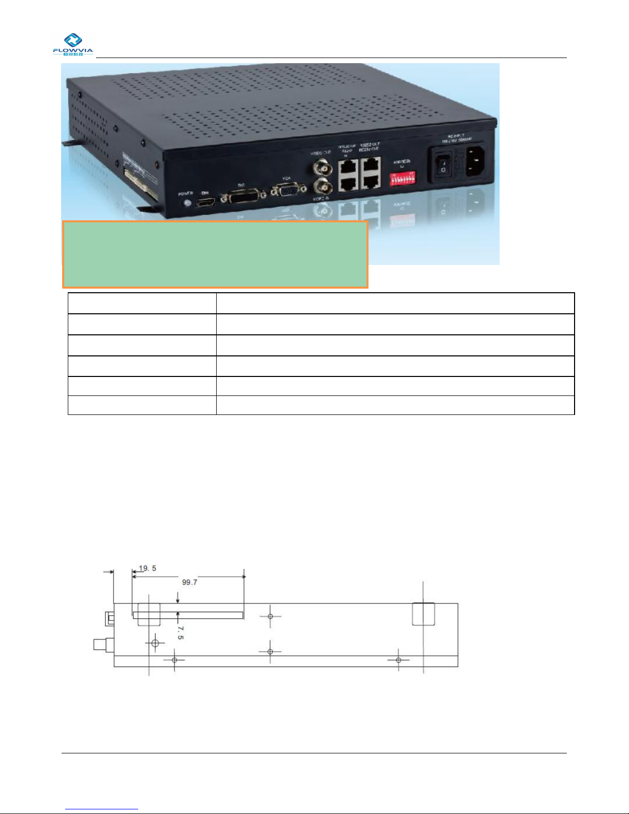
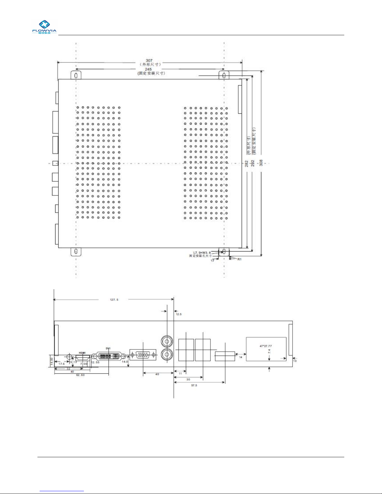
Chapter 3: Size definitions
Structural dimensions
The left side of the interface for the high voltage power supply and
screen brightness, switch control interface, please use the dedicated
cable with random, please note the connection, plug direction, other
alternatives may damage the machine or your screen
FLW-717C Product Manual
Shenzhen City Chang Rui Technology Co., Ltd

FLW-717C Product Manual
Shenzhen City Chang Rui Technology Co., Ltd
Chapter 4: Setup poster
serial number
Explanation
One,Two,Four,Fives
LCD backlight power cord.
three、Eight
Internal cooling fan connector.
Six
Temperature sensing interface.
Seven
Motherboard power line interface.
Nine
External cooling fan connector.

FLW-717C Product Manual
Shenzhen City Chang Rui Technology Co., Ltd
4.1 Installation:
1、Install cooling fan and AC power holder.
2、Install the power board and the power cord.
3、Install the motherboard and motherboard cable.

FLW-717C Product Manual
Shenzhen City Chang Rui Technology Co., Ltd
chapter 5: Burning Software
5.1 Software Upgrade Guide
FLW-717C / M59W upgrade there are two kinds of ways 1:USB Upgrade. 2:ISP Upgrade.
5.2 USB upgrade steps
First, the need to burn copies of the software to the U disk Software name is fixed FLW_V59.bin.
The USB connection to M59W board RJ45 port via USB to RJ45 cable,As shown below:

FLW-717C Product Manual
Shenzhen City Chang Rui Technology Co., Ltd
5.3 ISP upgrade
PC Tools driver will be installed first ISP ISP tools to connect to port M59W M59W board
CN3 on electricity.
Click Open ISP_Tool After the connection is successful chip models will pop
up display, for example:
Table of contents


