ChangHung Telecom CT-4L User manual

HOME DVR
MANUAL
MANUALMANUAL
MANUAL
CHANGHUNG TELEOCM LTD.
CHANGHUNG TELEOCM LTD.CHANGHUNG TELEOCM LTD.
CHANGHUNG TELEOCM LTD.
www.changhung.com
www.changhung.comwww.changhung.com
www.changhung.com
#3996,SUJIN
#3996,SUJIN#3996,SUJIN
#3996,SUJIN-
--
-DONG,SUJUNG
DONG,SUJUNGDONG,SUJUNG
DONG,SUJUNG-
--
-KU,SUNGNAM
KU,SUNGNAMKU,SUNGNAM
KU,SUNGNAM-
--
-CITY,
CITY,CITY,
CITY,
KYUNGGI
KYUNGGIKYUNGGI
KYUNGGI-
--
-DO,KOREA,461
DO,KOREA,461DO,KOREA,461
DO,KOREA,461-
--
-806
806806
806
TEL :031
TEL :031TEL :031
TEL :031-
--
-757
757757
757-
--
-5153
51535153
5153
FAX :031
FAX :031FAX :031
FAX :031-
--
-753
753753
753-
--
-3885
38853885
3885

CONTENTS
CONTENTSCONTENTS
CONTENTS
CLAUSE 1
CLAUSE 1CLAUSE 1
CLAUSE 1:
::
:H/W INSTALLA
H/W INSTALLAH/W INSTALLA
H/W INSTALLATION
TIONTION
TION
1. Specification of Home DVRBoard
1. Specification of Home DVRBoard1. Specification of Home DVRBoard
1. Specification of Home DVRBoard
2. Specification of I/OBoard
2. Specification of I/OBoard2. Specification of I/OBoard
2. Specification of I/OBoard
3. Requirements of System
3. Requirements of System3. Requirements of System
3. Requirements of System
4. Board Configuration
4. Board Configuration4. Board Configuration
4. Board Configuration
CLAUSE 2 :INSTALLATION OF DRIVER & PROGRAM
CLAUSE 2 :INSTALLATION OF DRIVER & PROGRAMCLAUSE 2 :INSTALLATION OF DRIVER & PROGRAM
CLAUSE 2 :INSTALLATION OF DRIVER & PROGRAM
1. The information in Driver CD.
1. The information in Driver CD.1. The information in Driver CD.
1. The information in Driver CD.
2. Driver Installation
2. Driver Installation2. Driver Installation
2. Driver Installation
3. Checkpoint of In
3. Checkpoint of In3. Checkpoint of In
3. Checkpoint of Installed Driver
stalled Driverstalled Driver
stalled Driver
4. Program Installation
4. Program Installation4. Program Installation
4. Program Installation
5. Program Operating Manual
5. Program Operating Manual5. Program Operating Manual
5. Program Operating Manual
6. Q & A
6. Q & A6. Q & A
6. Q & A

CLAUSE 1 : H/W INSTALLATION
CLAUSE 1 : H/W INSTALLATIONCLAUSE 1 : H/W INSTALLATION
CLAUSE 1 : H/W INSTALLATION
MODEL :CT
MODEL :CTMODEL :CT
MODEL :CT-
--
-4L RCA V1.0
4L RCA V1.04L RCA V1.0
4L RCA V1.0
1. Specification of Home DVRBoard
1. Specification of Home DVRBoard1. Specification of Home DVRBoard
1. Specification of Home DVRBoard
-Camera Input !!!!!!!!!!!!!!!!!!!!!!!!!! 4CH
-Audio Input !!!!!!!!!!!!!!!!!!!!!!!!!! 1CH
-TV Output !!!!!!!!!!!!!!!!!!!!!!!!!! 1CH
2. Specification of I/OBoard
2. Specification of I/OBoard2. Specification of I/OBoard
2. Specification of I/OBoard
-Sensor Input !!!!!!!!!!!!!!!!!!!!!!!!!! 4CH
-Alarm Output !!!!!!!!!!!!!!!!!!!!!!!!!! 4CH
3. Requirements of System
3. Requirements of System3. Requirements of System
3. Requirements of System
-Os !!!!!!!!!!!!!!!!!!!!!!!!!! Windows98, 98SE
-Operating Circumstance !!!!!!!!!!!!!!!!!!!!!!!!!! CPU–MMX 200 & above
RAM –32MB & above
VGA –AGP 4MB & above

4. BOARD Configuration
4. BOARD Configuration4. BOARD Configuration
4. BOARD Configuration
♦
♦♦
♦TV OUT (RCA1)
TV OUT (RCA1)TV OUT (RCA1)
TV OUT (RCA1)
♦
♦♦
♦SENSOR INPUT TERMINAL (CN1)
SENSOR INPUT TERMINAL (CN1)SENSOR INPUT TERMINAL (CN1)
SENSOR INPUT TERMINAL (CN1)
♦
♦♦
♦ALARM OUT TERMINAL (CN2)
ALARM OUT TERMINAL (CN2)ALARM OUT TERMINAL (CN2)
ALARM OUT TERMINAL (CN2)
♦
♦♦
♦
SENSOR INPUT&ALARM OUT PORT (CN3)
SENSOR INPUT&ALARM OUT PORT (CN3)SENSOR INPUT&ALARM OUT PORT (CN3)
SENSOR INPUT&ALARM OUT PORT (CN3)
Pin No. Pin Spec Pin No. Pin Spec
1SENSOR4 2 GND
3SENSOR3 4GND
5SENSOR2 6GND
7SENSOR1 8N.C
910 “
11 OUT1 12 “
13 14 “
15 OUT2 16 “
17 18 “
19 OUT3 20“
2122 “
23OUT4 24“
25TV OUT
26TV OUT
26
2626
26
25
2525
25
2
22
2
1
11
1

4
44
4-
--
-1 Configuration
1Configuration1Configuration
1Configuration
4
44
4-
--
-2 CABLE ASS
2 CABLE ASS2 CABLE ASS
2 CABLE ASS’
’’
’Y
YY
Y
300mm
<HIF3BA-26D-2.54R> <HIF3BA-26D-2.54R>
Difference :+,- 10MM
12
25 26
1
25
2
26
CN
CN
LINE MONITOR
<SENSOR & ALARM>
<CT-4L TER B/D>
Sensor Input
Sensor Output
Ch2
Ch3
Ch4
Ch1
Ch2
Ch3
Ch4
Ch1

HERDER 26PIN
(HIF3BA-26D-2.54R)
HERDER 26PIN
(HIF3BA-26D-2.54R)
1!" 1
2 !" 2
3!" 3
4!" 4
5!" 5
21!" 21
22 !" 22
23!" 23
24!" 24
25!" 25
26!" 26
4
44
4-
--
-3
33
3RCA TYPE(MODEL :CT
RCA TYPE(MODEL :CTRCA TYPE(MODEL :CT
RCA TYPE(MODEL :CT-
--
-4L RCA V1.0)
4L RCA V1.0)4L RCA V1.0)
4L RCA V1.0)
1) Constructing Unit
<CT
<CT<CT
<CT-
--
-4L RCA B/D
4L RCA B/D4L RCA B/D
4L RCA B/D–
––
–1EA> <MANUAL> <DRIVER SETUP CD>
1EA> <MANUAL> <DRIVER SETUP CD>1EA> <MANUAL> <DRIVER SETUP CD>
1EA> <MANUAL> <DRIVER SETUP CD>
2) Option
<Ct
<Ct<Ct
<Ct-
--
-4L TER. B/D
4L TER. B/D4L TER. B/D
4L TER. B/D–
––
–1EA> <I/OCABLE
1EA> <I/OCABLE1EA> <I/OCABLE
1EA> <I/OCABLE –
––
–1EA> <I/OTER.
1EA> <I/OTER.1EA> <I/OTER.
1EA> <I/OTER. –
––
–1SET(2EA)>
1SET(2EA)>1SET(2EA)>
1SET(2EA)>
U1
RCA1
RCA2
RCA5
RCA4
RCA3
CN2 CN1
CN3
RCA1

4
44
4-
--
-4 NAME OF E
4NAME OF E4 NAME OF E
4NAME OF EACH PART
ACH PARTACH PART
ACH PART
<CT
<CT<CT
<CT-
--
-4L RCA B/D>
4L RCA B/D>4L RCA B/D>
4L RCA B/D>
1. CAMERA INPUT 1~4CH JACK (RCA1
1. CAMERA INPUT 1~4CH JACK (RCA11. CAMERA INPUT 1~4CH JACK (RCA1
1. CAMERA INPUT 1~4CH JACK (RCA1-
--
-RCA4) & TV OUT (RCA5)
RCA4) & TV OUT (RCA5)RCA4) & TV OUT (RCA5)
RCA4) & TV OUT (RCA5)
2. CAMERA INPUT MOLEX (CON2)
2. CAMERA INPUT MOLEX (CON2)2. CAMERA INPUT MOLEX (CON2)
2. CAMERA INPUT MOLEX (CON2)
3. AUDIO INPUT (CON1)
3. AUDIO INPUT (CON1)3. AUDIO INPUT (CON1)
3. AUDIO INPUT (CON1)
4. SENSOR INPUT&ALARM OUT PORT (CON3)
4. SENSOR INPUT&ALARM OUT PORT (CON3)4. SENSOR INPUT&ALARM OUT PORT (CON3)
4. SENSOR INPUT&ALARM OUT PORT (CON3)
4
44
4-
--
-5 Specification of Connector Pin
5Specification of Connector Pin5Specification of Connector Pin
5Specification of Connector Pin
The others of Connec
The others of ConnecThe others of Connec
The others of Connector Pin Spec. is the same with BNC TYPEB/D(CT
tor Pin Spec. is the same with BNC TYPEB/D(CTtor Pin Spec. is the same with BNC TYPEB/D(CT
tor Pin Spec. is the same with BNC TYPEB/D(CT-
--
-4L BNC)
4L BNC)4L BNC)
4L BNC)
except CAMERA INPUT BNC TYPEB/D(CT
except CAMERA INPUT BNC TYPEB/D(CTexcept CAMERA INPUT BNC TYPEB/D(CT
except CAMERA INPUT BNC TYPEB/D(CT-
--
-4L BNC).
4L BNC).4L BNC).
4L BNC).
♦
♦♦
♦CAMERA INPUT (out)
CAMERA INPUT (out)CAMERA INPUT (out)
CAMERA INPUT (out) –
––
–RCA1~RCA4
RCA1~RCA4RCA1~RCA4
RCA1~RCA4
BNC No. CAMERA CH
RCA1 CH1
RCA2 CH2
RCA3 CH3
RCA4 CH4
RCA5 TV Out
4
44
4
2 3
2 32 3
2 3
1
11
1

♦
♦♦
♦CAMERA INPUT MOLEX (CON2)
CAMERA INPUT MOLEX (CON2)CAMERA INPUT MOLEX (CON2)
CAMERA INPUT MOLEX (CON2)
Pin No. Pin Spec
1CH1
2 CH2
3CH3
4CH4
5GND
♦
♦♦
♦AUDIO INPUT (CON1)
AUDIO INPUT (CON1)AUDIO INPUT (CON1)
AUDIO INPUT (CON1)
Pin No. Pin Spec
1Audio In
2 GND
11
52

CH1
CH1CH1
CH1
CH2
CH2CH2
CH2
CH3
CH3CH3
CH3
CH4
CH4CH4
CH4
U1
RCA1
RCA2
RCA5
RCA4
RCA3
4
44
4-
--
-6 Configuration
6Configuration6Configuration
6Configuration
Excluded SENSOR INPUT&ALARM OUT
Excluded SENSOR INPUT&ALARM OUTExcluded SENSOR INPUT&ALARM OUT
Excluded SENSOR INPUT&ALARM OUT
<CAMERA>
<CT-4L RCA B/D>
LINE MONITOR

5. Others
5. Others5. Others
5. Others
5
55
5-
--
-1 GPIO ADDRESS MAP
1GPIO ADDRESS MAP1GPIO ADDRESS MAP
1GPIO ADDRESS MAP
GPIO Port Bits Signal Name Remark
[23] 23N.C
[22] 22 N.C
[21] 21N.C
[20] 20N.C
[19] 19 N.C
[18] 18 N.C
[17] 17 N.C
[16] 16 N.C
[15] 15 Line Out Enable
[14] 14 Line Out
[13] 13 Line Out
[12] 12 Line Out
[11] 11 Sensor1
[10] 10 Sensor2
[9] 9Sensor3
[8] 8Sensor4
[7] 7N.C
[6] 6N.C
[5] 5Alarm Out Enable
[4] 4Alarm Out Enable
[3] 3Alarm Out4
[2] 2 Alarm Out3
[1] 1Alarm Out2
[0] 0Alarm Out1
♦
♦♦
♦SENSOR INPUT
SENSOR INPUTSENSOR INPUT
SENSOR INPUT
Signal Name GPIO PORT Remark
CH1INPUT GPIO11 Low Active
CH2 INPUT GPIO10 Low Active
CH3INPUT GPIO9 Low Active
CH4INPUT GPIO8 Low Active
♦
♦♦
♦ALARM OUTPUT
ALARM OUTPUTALARM OUTPUT
ALARM OUTPUT
Signal Name GPIO PORT Remark
CH1OUT GPIO 0High Active
CH2 OUT GPIO 1High Active
CH3OUT GPIO 2 High Active
CH4OUT GPIO 3High Active
Output Enable GPIO 4Low Active
Output Enable GPIO 5High Active

♦
♦♦
♦LINE OUTPUT
LINE OUTPUTLINE OUTPUT
LINE OUTPUT
Signal Name GPIO PORT Remark
Address 00 GPIO 12 High Active
Address 01 GPIO 13 High Active
Address 02 GPIO 14 High Active
Output Enable GPIO 15 High Active
GPIO PORT
Working Condition GPIO15 GPIO 14 GPIO 13 GPIO 12
NOT USED 0XXx
CH1OUT 1000
CH2 OUT 1001
CH3OUT 1010
CH4OUT 1011

CLAUSE 2 INSTALLATION OF DRIVER & PROGRAM
CLAUSE 2 INSTALLATION OF DRIVER & PROGRAMCLAUSE 2 INSTALLATION OF DRIVER & PROGRAM
CLAUSE 2 INSTALLATION OF DRIVER & PROGRAM
Home DVRis operated on the condition of WIN98 perfectly. Before installing Home DVR,
Please user check that operating system of Home DVRwas installed on user’s PC
system and no problem to operate the system in advance. In case of operating system
normally without any problems,please complete the installation as following directions.
1. Please switch off the power of PCsystem completely.
2. Please open the PCCase.
3. After checking vacant PCI slot of 32 BIT on PC, Please put the card into the
vacant PCI slot of 32 BIT on PC..
4. After lid case of PC, please connect with power supply
1. The information in Driver CD
1. The information in Driver CD1. The information in Driver CD
1. The information in Driver CD
-Home DVRDriver for WIN98
-Home DVRSetup Program
-User Manual
-WM-Tools 4.1
-DirectX7.0a
-Acrobat 4.0

2. Driver Installation
2. Driver Installation2. Driver Installation
2. Driver Installation
1. please execute system and then operate O/SSystem of WIN98.
2. After operating WIN98 O/S, will be operated with the following message;
the message screen that found out “Add New Hardware Wizard”
of new hardware”. Please click“NEXT”.
3. After selecting “search for the best driver for your device(Recommended)”,
Please click “NEXT”.
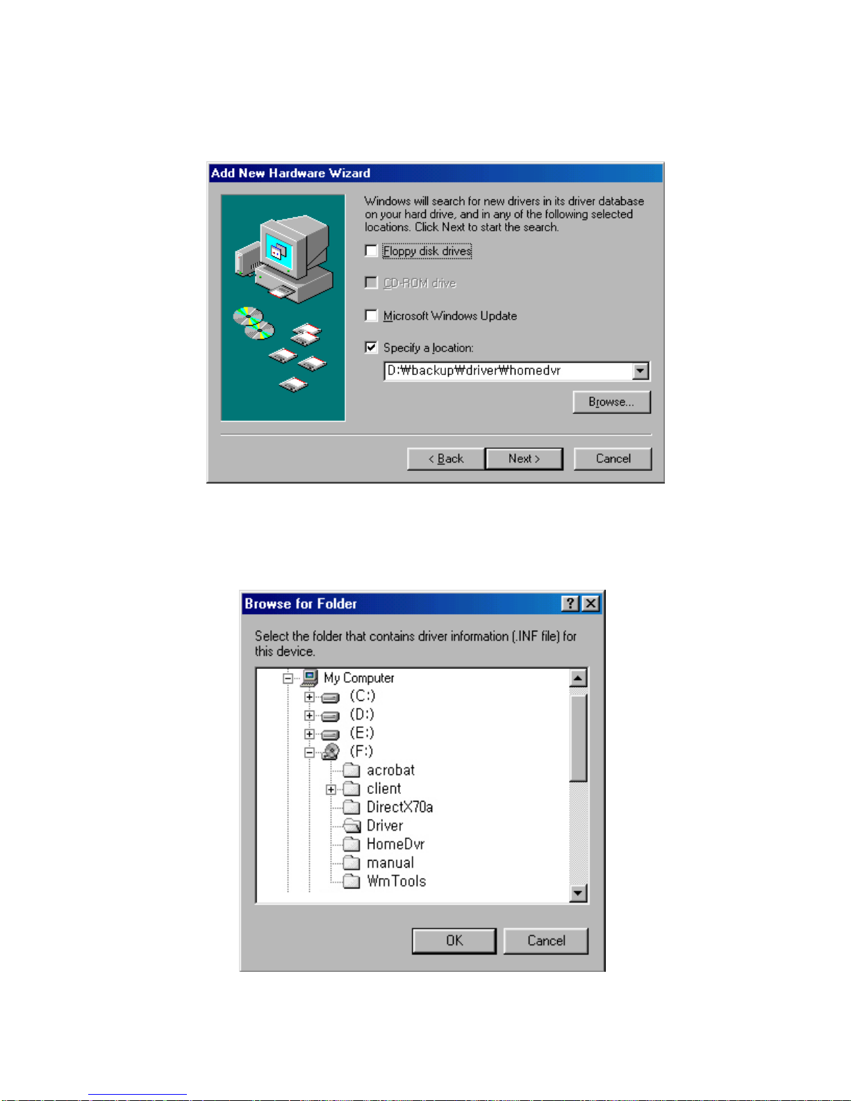
4. Please check at “Add New Hardware Wizard”. Then,please click “Browse...”.
5. User can see the following several folder if it click the drive which is installed CD-
ROM at “Browse for Folder”. Among them,open the folder of “Driver”
And then click “OK”.

6. Please click “NEXT”.
7. If it is all correct the device that seek for driver & the location of driver,
Please click “NEXT”.

8. If the installation of driver is completed,driver installation of Home DVRBoard is
finished completely. Please click “FINISH”.

3. Checkpoint of Installed Driver
3. Checkpoint of Installed Driver3. Checkpoint of Installed Driver
3. Checkpoint of Installed Driver
After installing driver,please check up whether the driver is activating with other
hardware well without no conflict .
1. At the beginning program,please open [Control Panel],and execute [SYSTEM].
2. At [System Properties ],please open [SOUND, VIDEO and GAME CONTROLLER].

3. Please select [CTEC 4Ch Capture Device],
and click [Properties] .
4. If appeared the following information,please check up the message that the device
is operated correctly at the tap of [GERNERAL]. If you can see the message,it
means that the driver is installed correctly.

5. Please check the conflicting reason of peripheral device which show at [CTEC 4ch
Capture Device Properties] into the tap of [RESOURCES] ,And solve the conflict by
taking adequate steps. In addition to that,user can check up IRQ NO. that Home
DVRBOARD is using now at this tap.
Due to the incompletion of WINDOW’s PnP(Plug & Play)function,it can be happened
IRQ conflict with other peripheral device in case of installing by the way of PnP .
In case of short of IRQ of System,or When the IRQ does not divide onto Home DVR
correctly,it does not operate PnP function normally.
If clicked computer list of system controller,your can see the condition of IRQ position .
At this moment,if IRQ is used commonly ,or IRQ is happened conflict,please switch off
the power,then please put HomeDVRcard into other PCI Slot,and reboot.
If it happen even the conflict of IRQ when the HomeDVRBoard put into another slot,
User need to appoint IRQ manually which is not used at CMOS Setup of Main Board.

4. Program Installation
4. Program Installation4. Program Installation
4. Program Installation
It should be installed DirectXand WMTools of MS SOFTWARE in order to use
HomeDVRcorrectly. If the newest version of DirectXand WMTools is installed,it is ok
not to select in option when setting up program.
At this hereafter section,will explain to install DirectX7.0a,WMTools 4.1with
HomeDVRprogram automatically.
1. Please execute [SETUP] at HomeDvr Folder of Driver CD.
Then,you can see the below box and it will execute beginning operation.
2. If appear the box to notify the [START] please operate “Next”button.
Table of contents


