Crest Electronics CDR-1104 User manual

Thank you for purchasing our product.
Please read this User s Manual before
using the product. Change without Notice
4 Channel DVR
User s Manual

2
CAUTION
RISK OF ELECTRICAL
SHOCK. DO NOT OPEN !
CAUTION: TO REDUCE THE RISK OF ELECTRICAL SHOCK,
DO NOT REMOVE COVER (OR BACK), NO USER
SERVICEABLE PARTS REFER SERVICING TO
QUALIFIED SERVICE PERSONNEL.
Safety Precautions
The lightning flash with arrowhead symbol, within an equilateral
triangle, is intended to alert the user to the presence of insulated
dangerous Voltage within the product s enclosure that may be
sufficient magnitude to constitute risk of electrical shock to persons.
The exclamation point within an equilateral triangle is intended to alert
the user to the presence of important operation and maintenance
(servicing) instructions in the literature accompanying the appliance.
WARNING: TO PREVENT FIRE OR SHOCK HAZARD, DO NOT
EXPOSE UNITS NOT SPECIFICALLY DESIGNED FOR
Attention: installation should be performed by qualified service
Personnel only in accordance with the National Electrical Code or
applicable local codes.
Power Disconnect. Units with or without ON-OFF switches have
power supplied to the unit whenever the power cord is inserted into
the power source; however, the unit is operational only when the
ON-OFF switch is the ON position. The power cord is the main power
disconnect for all unites.
There are no serviceable parts for this unit, call for your agent for
details.
Warranty
and Service

3
Before installing stand alone DVR, be sure to thoroughly review and follow the instructions in this
User s Manual. Pay particular attention to the parts that are marked NOTICE.
Also, when connecting with external application, first turn the power OFF and follow manual
instruction for appropriate installation.
1. This document is intended for both the administrator and users of stand alone DVR Model.
2. This manual contains information for configuring, managing and using stand alone DVR
Model.
3. To prevent fire or electrical shock, do not expose the product to heat or moisture.
4. Be sure to read this manual before using stand alone DVR Model.
5. For questions and technical assistance of this product, contact your local dealer.
►Strong recommendation on installation of the DVR unit
1. Check electricity at the place you want to install the DVR unit is stable and meets our
electricity requirements. Unstable electricity will cause malfunction of the unit or give critical
damage to the unit.
2. Several chips on the main board of the DVR unit and hard disk drive inside the unit generate
heat, and it must be properly discharged. Do not put any objects just beside exhaust port(fan)
on the left side of the unit and do not close up an opening (fresh air in-take) on the right side
of the unit..
About this document
Before reading this document

4
1.PLAY Video playback function .
2.REC Record button (Start / Stop )
3.SHIFT + MODE Change the record quality level . (HST / HIG / NOR / LOW / LST).
4.SHIFT Video backup function.
5.MODE
Change display mode (quad mode )/ Full channel select
6.MENU Display menu setup
7.ENTER Change the setting value .
8. UP / STOP Direction button UP / Playback stop button ▲/▓
9. DOWN / PAUSE Direction button down / Playback pause ▼/ ▌▌
10. REW Direction left button/ Reverse playback / play speed /
11. FF Direction right button/ Forward playback / play speed /
FRONT PANEL

5
1. DC IN Power code in 12V/ 5A
2. USB USB device slot
3. CAM IN Camera 1 ~ 4 input BNC type
4. MONITOR Monitor out
REAR PANEL

6
The key on the remote controller function control is same as the front keypad of the unit.
REC
Record button (Start / Stop )
MENU Display menu setup
BACKUP Video backup function.
SEARCH
Video search function
HST Video record quality level (Highest)
HIG Video record quality level (High)
NOR Video record quality level (Normal)
LOW Video record quality level (Low)
LST Video record quality level (Lowest)
ENTER Change the setting value .
Direction button UP /
Playback stop button
Direction button down /
Playback pause
Direction right button /
Forward playback / play speed
Direction left button /
Reverse playback / play speed
~Channel 1 ~ channel 4
Full screen display
Quad display screen
REMOTE Controller

7
Power on the DVR system , the real-time video can be seen by 4 quad screen or full screen display .
User can press MODE button to switch the display mode .
Playback mode : Press PLAY button , user can search date-time to playback .
Record mode : Press REC button start to record . User can press SHIFT + MODE button to
change the record quality .Record quality level have 5 types : HST / HIG / NOR / LOW / LST .
Press SHIFT button , it will show an icon at top line on screen then press MODE button to
change record frame rate and quality level and it will show a message on top-right screen .
User change the different record level , it means that user change the record quality , below table
show the mapping .
Level HST HIG NOR LOW LST
FPS 60
(15/each)
60
(15/each)
16
(4/each)
8
(2/each)
8
(2/each)
Quality High Normal Normal Normal Low
Backup mode :
Before backup, USB device is required. User need insert USB device into USB slot before backup.
Backup file size can not exceed 3GB
1. On playback mode, press SHIFT button to start backup.
2. When user press SHIFT button , it means the start time of backup .
3. When user press SHIFT button second time , it means the end time of backup .
4. The system will auto reading USB device then start to backup data .
1 . OPERATION

8
Icon Indicator:
In live mode or playback mode , the icons show at top line on screen to notify user the system status ,
below are the icons status .
Live mode
Forward
Recording
Pause
Video loss
Reverse
Motion detect
SHIFT mode
Display Channel
Hard disk usage

9
When user first time use admin menu setup , please press direction key
▲ ▲ ▼ ▼ and MENU ,then user can into admin menu setup successful.
2.1 Camera Setup
User can setup each channel display status and adjust the cameras Brightness , contrast, hue
and saturation . Right adjustment of each element will increase picture quarterly displayed. We
recommend you to adjust each element of cameras and monitor to be connected to the DVR .
Display : On / Off, if display set off , the channel will be hidden
2.2 Record Setup Use this function to setup the record frame rate of each channel
2 . SYSTEM SETUP
Totally frame rate is
60 fps(NTSC) / 50 fps (PAL)

10
2.2.1 Schedule Record Frame rate
User can use the direction left button to decrease the frame rate or direction right button
to increase the frame rate value .
After changed the frame rate value , press MENU button to exit the setup menu .
Schedule record will follow these frame rate values .
2.2.2 Motion Record Frame rate
User can use the direction left button to decrease the frame rate or direction right button
to increase the frame rate value .
After changed the frame rate value , press MENU button to exit the setup menu .
Motion record will follow these frame rate values .
2.2.3 Record Quality:
Low / Normal / High (See record time table page 11)
2.2.4 Event Rec Duration:
5/ 10/ 15/ 20/ 25/ 30 seconds. Duration time recording after event
2.2.5 Auto Record:
Off / 1 ~ 8 minutes selectable
When auto record is set to 1 ~ 8 minutes , the DVR will start recording after 1~ 8 minutes no
operation .

11
2.2.6 Data Retention:
OFF / 1 ~ 15 days selectable
2.2.7 Schedule Record
Use the left button or right button to select time and use the Enter button to change
record type .
Notice:
1. Each channel has own frame rate adjustment in different recording mode.
2. In 24 hours, user can adjust each channel frame rate in different record mode. Such as schedule,
motion detection, and alarm record mode
3. Press ENTER button to change different record mode
Record Time Table: 80GB HD
Record Quality: Low. Average: 5 KB;
REC FPS(total) 60 30 15 10
REC Hour 72 hr 148 hr 296 hr 444 hr
Record Quality: Normal. Average 10 KB;
REC FPS(total) 60 30 15 10
REC Hour 36 hr 74 hr 148 hr 222 hr
Record Quality: High. Average 20 KB;
REC FPS(total) 60 30 15 10
REC Hour 18 hr 37 hr 74 hr 111 hr
**Actual recording time is base on live environment. This table is only for reference.**
20 K x 30 (frame rate) x 60 (mins) x 60 (secs) = 2160000 K = 2160 M / hr
2160 M / hr x 24 = 51840000 K = 51840 M = 51.84 G / (1 Day)

12
2.3 Motion Detection
User can setup each channel with different motion detection .
2.3.1 Channel :
User can setup different motion detection of channels (1~ 4 )
2.3.2 Sensitivity :
Off / Low / Normal / High
2.3.3 Pop up :
OFF/ 1 ~ 30 Seconds /CONT
Alarm POP UP: Each channel jumps to full screen when alarm triggered. Quad screen display
if more than two cameras alarm triggered.
2.3.4 Motion Area
Use direction button Left or Right to move position then press ENTER button , start to select
the motion area and finally press ENTER button to stop .
Detected area

13
2.4 SCREEN
Let user setup the screen display
2.4.1 SCREEN: Split border on or off .
2.4.2 Video Adjustment: Video screen position movement. Use direction button to move.
2.4.3 Video system :
NTSC/ PAL/ AUTO
2.5 System Setup
2.5.1 Hard Disk Setup :
Overwrite Enable : Yes -> When Hard Disk full , DVR continue to record
No -> When Hard Disk full , DVR stop record .
Format HDD : Initial the HDD , Please format hard disk before starting record
ON OFF

14
2.5.2 Time Setup
User can setup time zone and daylight saving time in this menu , also can use up-down
button move to time set change the date and time.
2.5.3 Buzzer Setup
2.5.5 F/W Upgrade
Stop all hard disk working before update, select F/W upgrade and then press ENTER to search
firmware.
1. Searching Firmware
2. Press PLAY upload, press STOP cancel
3. Firmware Reading
4. Firmware uploading
DVR auto reboot after F/W upgrade finished .
System Buzzer: OS operating
Key Press Buzzer: Button operating
Motion Buzzer: Motion detection warning
Video Loss Buzzer Video loss warning

15
2.5.6 Load Player Software
Stop all hard disk working and insert USB device into USB slot before load Player Software
then press ENTER . After press ENTER, the system will search software file from USB device.
After the file is detected, the system auto load player file when finished it return to setup menu.
Player Software is loaded in hard disk as factory default. Just in case if user change a new
hard disk.

16
2.6 Search
User can search video image by Time list , Event list and Time search .
2.6.1 Time List mode
Use direction button up and down to select date and time section, and then press ENTER start to
playback. Time list total can save 120 records
2.6.2 Event List mode
Each event will list on event list , user can use direction button up and down to move and it will show
the event start time and end time for user reference . After select an event press ENTER start to
playback. Event list total can save 120 records

17
2.6.3 Time Search:
1. Press ENTER into time search menu .
2. Use direction left or right button to move the cursor position .
3. Press ENTER to change date and time .
4. Press MENU return to the previous screen and move cursor to Search.
5. Press ENTER to start the searching.
6. Wait until the unit starts to playback.
Playback mode
Forward speed: x 2 / x 3 / x 4
(Direction right button)
Reverse speed: x 8 / x 16 / x 32
(Direction left button)
Press STOP button return to live mode.

18
2.7 Language
Standard is English / Chinese
2.8 Exit
User needs to save changes if any function value has changed then exit menu.

19
Start to play :
1 Fast Reverse 6 Play
2 Play Reverse 7 Fast Forward
3 Previous Frame 8 Full Screen (manual switch)
4 Pause 9 Quad Screen
5 Next Frame 10 Capture image
AVI Button: .vvf files export to .avi format
Browse for the source file
Browse a path for file output
Select a compression codec
Percentage of the export AVI progress
cde f ghijkl
3 . Player Software

20
Model 4 CH Digital DVR
Input 4 CH Inputs 1.0Vp-p, 75ohm unbalanced (BNC Type)
Output Main monitor x 1
S/N Ratio More than 40dB
0Color 6.7 Million
Monitoring Method
Channel Display Single / Quad channel
Screen Quality 640(H) x 448(V) Active Pixels(NTSC);
640(H) x 544(V) Active Pixels (PAL)
Display Rate 120 fps (NTSC) / 100 fps (PAL)
Recording/ Play Function
Recording (Max) NTSC Max 60 fps(NTSC); Max 50 fps(PAL)
Record Quality High, Normal, Low
Compressed Picture Storage: M-JPEG
Recording Control Normal / Schedule / Event
Motion detect Record 5 ~ 30 seconds
Playback Mode Time list / event list / Date & Time search
Backup and Copy
Backup Event Backup / Video Data backup via USB device
Backup file play Client software to play files
Other Function
Operation Mode Record / Play
Monitoring Firmware Watchdog
Recovery Auto-Reboot by Watchdog
Operation Mode Duplex (Record +Playback )
Control Device Front key/ Remote controller
Daylight Saving Supported
Language English / Chinese
Motion Detect 16 x16 grids camera for all channel
Storage 3.5 inch HDD x 1 SATA
Firmware Upgrade Support USB firmware upgrade
HDD Record Mode Full stop / overwrite
Power Supply DC12V
Operating Temperature 0 ~ + 55
4 . Specification
Other manuals for CDR-1104
1
Table of contents
Other Crest Electronics DVR manuals
Crest Electronics
Crest Electronics CDVS-7000 User manual
Crest Electronics
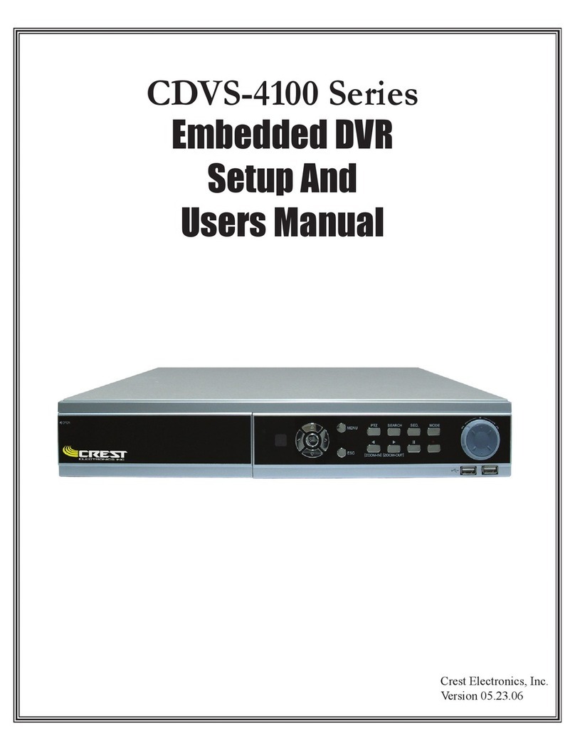
Crest Electronics CDVS-4100 Series User manual

Crest Electronics
Crest Electronics CDVS-7000 User manual

Crest Electronics
Crest Electronics CDR-1104 User manual

Crest Electronics
Crest Electronics CDVS-7000 User manual

Crest Electronics
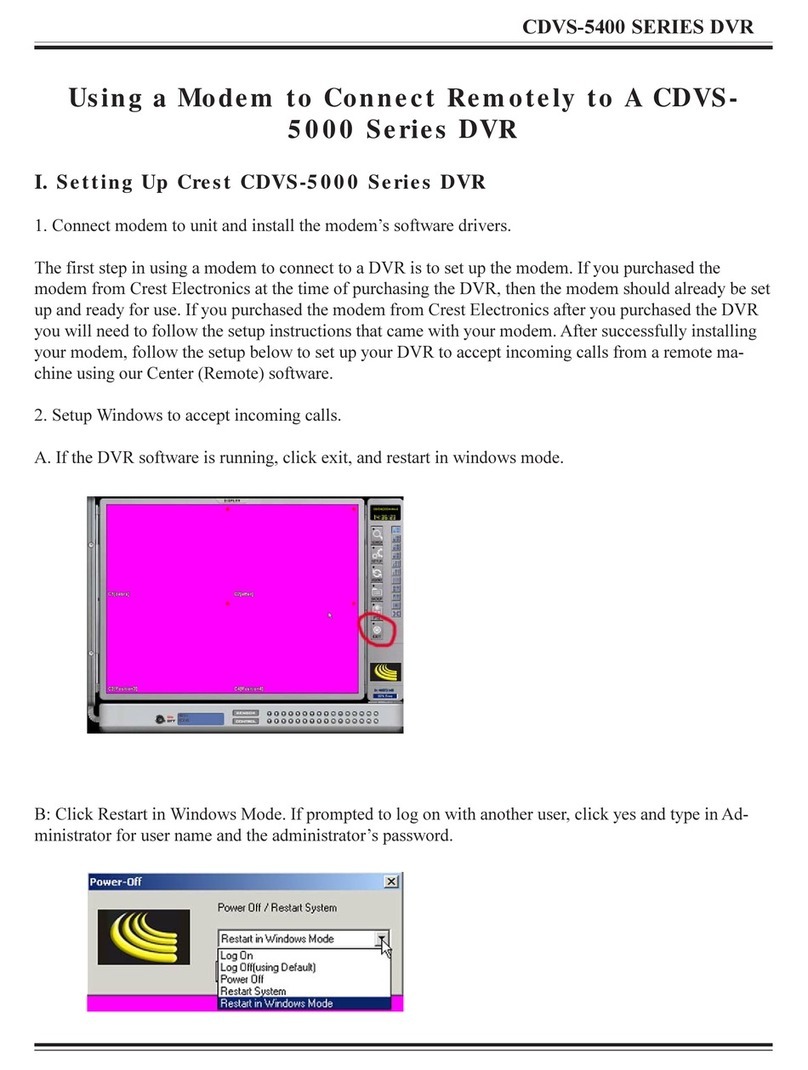
Crest Electronics CDVS-5400 SERIES User manual
Crest Electronics
Crest Electronics CDVS-5000 Series User manual


