Channel Master Digital ready User manual
CIJaDDeI
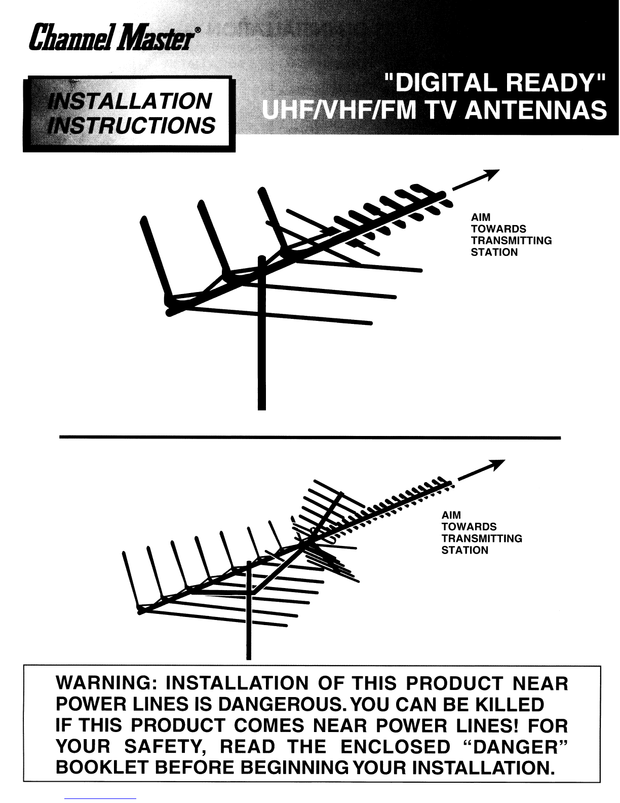
AIM
TOWARDS
TRANSMITTING
STATION
AIM
TOWARDS
TRANSMITTING
STATION
..
.....
------.:::II:-:=:
-
--
WARNING:
INSTALLATION
OF THIS
PRODUCT
NEAR
POWER LINES IS DANGEROUS.
YOU
CAN BE KILLED
IF THIS PRODUCT COMES NEAR POWER LINES! FOR
YOUR SAFETY,
READ
THE
ENCLOSED
"DANGER"
BOOKLET
BEFORE BEGINNINGYOUR INSTALLATION.
TIPS
ON
INSTALLATION
TOOLS YOU
WILL
FIND HANDY
•Large and small blade screwdrivers
•Adjustable Wrench
WHERETO MOUNTYOUR
ANTENNA
•Wire Cutters
•Pliers
Your
antenna can
be
mounted
on
eitherthe chimney, the roof, or
on
an
outside wall or
in
an
attic. Choose the method
that best suits your particular location.
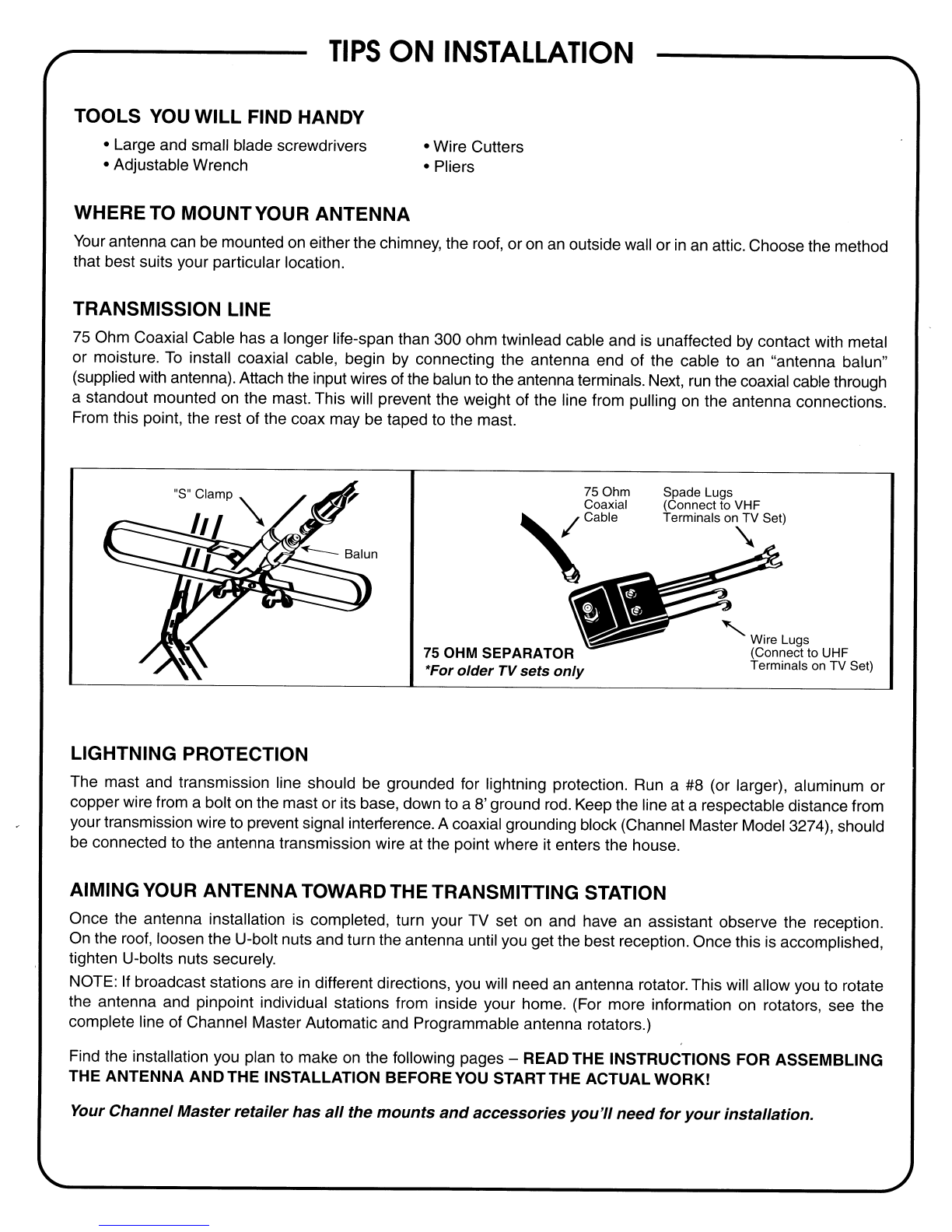
TRANSMISSION LINE
75
Ohm Coaxial Cable has alonger life-span than 300 ohm twinlead cable and
is
unaffected by contact with metal
or moisture.
To
install coaxial cable, begin
by
connecting the antenna end of the cable to
an
"antenna balun"
(supplied with antenna). Attach the input wires of the balun to the antenna terminals. Next,
run
the coaxial cable through
astandout mounted on the mast. This will prevent the weight of the line from pulling
on
the antenna connections.
From this point, the rest of the coax may be taped to the mast.
LIGHTNING PROTECTION
75 OHM SEPARATOR
*For
older
TV
sets
only
Spade Lugs
(Connect to VHF
Terminals
on
TV Set)
"
".
Wire Lugs
(Connect to UHF
Terminals on TV Set)
The mast and transmission line should be grounded for lightning protection.
Run
a
#8
(or larger), aluminum or
copper wire from abolt
on
the mast or its base, down to a8' ground rod. Keep the line at arespectable distance from
your transmission wire to prevent signal interference. Acoaxial grounding block (Channel Master Model 3274), should
be connected to the antenna transmission wire at the point where it enters the house.
AIMING YOUR ANTENNATOWARDTHETRANSMITTING STATION
Once the antenna installation
is
completed, turn your TV set on and have an assistant observe the reception.
On
the roof, loosen the U-bolt nuts and turn the antenna until you get the best reception. Once this
is
accomplished,
tighten U-bolts nuts securely.
NOTE: If broadcast stations are
in
different directions, you will need
an
antenna rotator. This will allow you
to
rotate
the antenna and pinpoint individual stations from inside your home. (For more information
on
rotators, see the
complete line of Channel Master Automatic and Programmable antenna rotators.)
Find the installation you plan to make
on
the following pages -READ THE INSTRUCTIONS FOR ASSEMBLING
THE ANTENNA ANDTHE INSTALLATION BEFORE
YOU
STARTTHE ACTUAL WORK!
Your
Channel
Master
retailer
has
all
the
mounts
and
accessories
you'll
need
for
your
installation.
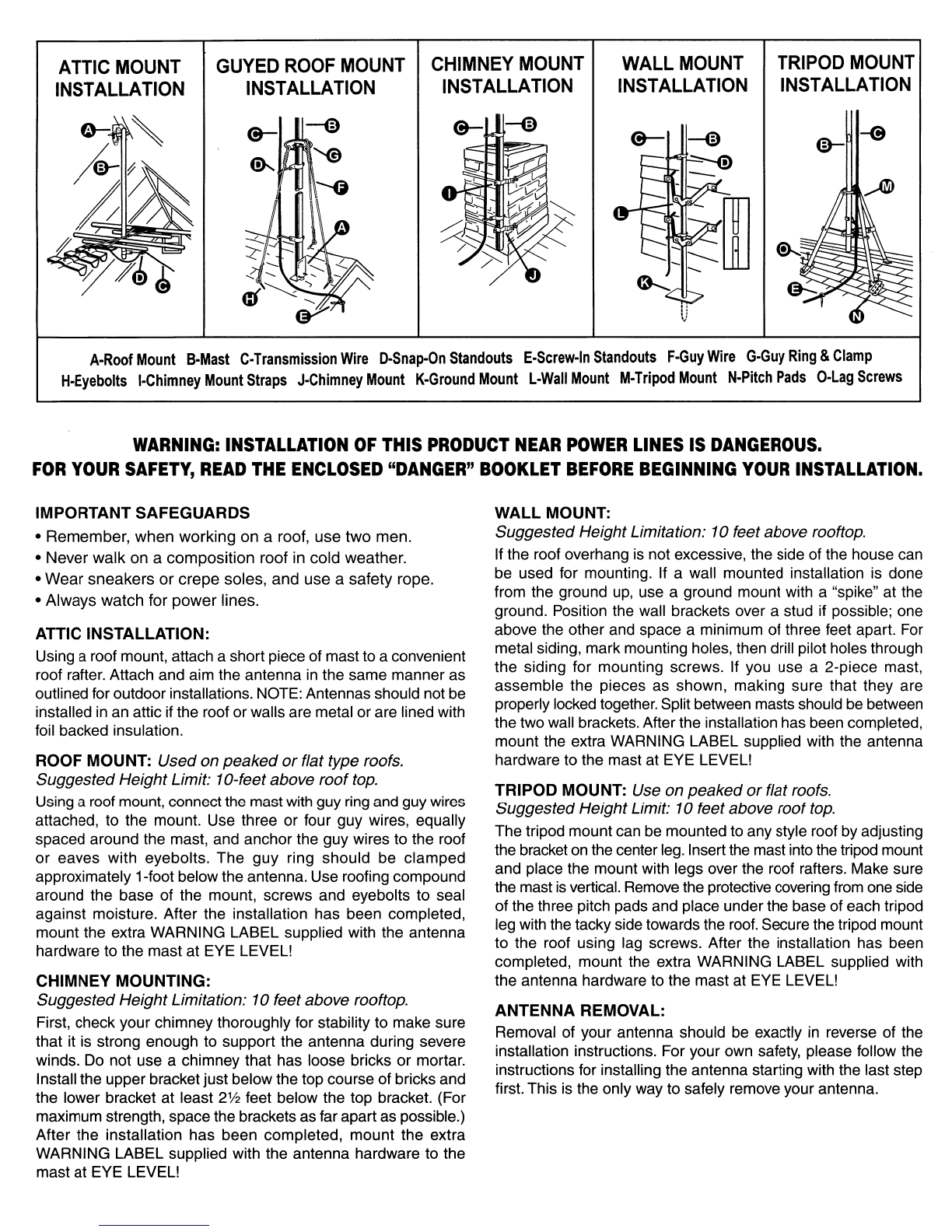
ATTIC
MOUNT
INSTALLATION
GUYED
ROOF
MOUNT
INSTALLATION
WALL
MOUNT
INSTALLATION
TRIPOD
MOUNT
INSTALLATION
A-Roof
Mount
B-Mast
C-Transmission
Wire
O-Snap-On
Standouts
E-Screw-In
Standouts
F-Guy
Wire
G-Guy
Ring
&
Clamp
H-Eyebolts
I-Chimney
Mount
Straps
J-Chimney
Mount
K-Ground
Mount
l-Wall
Mount
M-Tripod
Mount
N-Pitch
Pads
O-lag
Screws
WARNING:
INSTALLATION
OF
THIS
PRODUCT
NEAR
POWER
LINES
IS
DANGEROUS.
FOR
YOUR
SAFETY,
READ
THE
ENCLOSED
"DANGER"
BOOKLET
BEFORE
BEGINNING
YOUR
INSTALLATION.
IMPORTANT SAFEGUARDS
•Remember, when working on aroof, use two men.
•Never walk on acomposition roof in cold weather.
•Wear sneakers
or
crepe soles, and use asafety rope.
•Always watch for power lines.
ATTIC INSTALLATION:
Using aroof mount, attach ashort piece of mast to aconvenient
roof rafter. Attach and aim the antenna
in
the same manner as
outlined for outdoor installations. NOTE: Antennas should not be
installed
in
an
attic if the roof or walls are metal or are lined with
foil backed insulation.
ROOF MOUNT: Used on peaked
or
flat type roofs.
Suggested Height Limit: 1a-feetabove roof
top.
Using aroof mount, connect the mast with guy
ring
and guy wires
attached, to the mount. Use three or four guy wires, equally
spaced around the mast, and anchor the guy wires to the roof
or
eaves with eyebolts. The guy ring should be clamped
approximately 1-foot below the antenna. Use roofing compound
around the base of the mount, screws and eyebolts to seal
against moisture. After the installation has been completed,
mount the extra WARNING LABEL supplied with the antenna
hardware to the mast at EYE
LEVEll
CHIMNEY MOUNTING:
Suggested Height Limitation: 1afeet above rooftop.
First, check your chimney thoroughly for stability to make sure
that it
is
strong enough to support the antenna during severe
winds.
Do
not use achimney that has loose bricks or mortar.
Install the upper bracket just below the top course of bricks and
the lower bracket at least 2% feet below the top bracket. (For
maximum strength, space the brackets as far apart as possible.)
After the installation has been completed, mount the extra
WARNING LABEL supplied with the antenna hardware to the
mast at EYE
LEVEll
WALL
MOUNT:
Suggested Height Limitation: 1afeet above rooftop.
If the roof overhang
is
not excessive, the side of the house can
be used for mounting. If awall mounted installation is done
from the ground
up,
use aground mount with a"spike" at the
ground. Position the wall brackets over astud if possible; one
above the other and space a minimum of three feet apart. For
metal siding, mark mounting holes, then drill pilot holes through
the siding for mounting screws. If you use a2-piece mast,
assemble the pieces as shown, making sure that they are
properly locked together. Split between masts should be between
the two wall brackets. After the installation has been completed,
mount the extra WARNING LABEL supplied with the antenna
hardware to the mast at EYE
LEVEll
TRIPOD MOUNT: Use on peaked
or
flat roofs.
Suggested Height Limit: 1afeet above roof
top.
The tripod mount can be mounted to any style roof
by
adjusting
the bracket
on
the center
leg.
Insert the mast into the tripod mount
and place the mount with legs over the roof rafters. Make sure
the mast
is
vertical. Remove the protective covering from one side
of the three pitch pads and place underthe base of each tripod
leg with the tacky side towards the
roof.
Secure the tripod mount
to the roof using lag screws. After the installation has been
completed, mount the extra WARNING LABEL supplied with
the antenna hardware to the mast at EYE
LEVEll
ANTENNA REMOVAL:
Removal of your antenna should be exactly
in
reverse of the
installation instructions. For your own safety, please follow the
instructions for installing the antenna starting with the last step
first. This
is
the only way to safely remove your antenna.

ANTENNA
ASSEMBLY
INSTRUCTIONS
TOWARDS
TRANSMIITING
STATlO~
TOWARDS
TRANSMIITING
STATION
~
-
-
rScrew
",
,
..
,/
rcrossarm
~
WingNutj~
~
Fig. 1
NOTE:
This
instruction
sheet
covers
all
models
in this series
1.
If antenna has a 2 or 3-section crossarm (boom), assemble the sections with
screws and wing nuts. (See Fig. 1). On 3-section antennas, assemble with the short
elements to the front of antenna and the long elements to the rear of antenna. When
assembling, push the front
or
rear sections into the center section with the slot in
the front
or
rear sections pushed against the rivet, holding the insulator
to
the
center section. This will line up the holes for the screw and wing nut.
2. Open all elements on the antenna. NOTE:The elements on this antenna are tightly
riveted.
To
avoid bending the elements while opening, grip the elements near the
rivets. (See Figs. 2&3).
3.
Swing
phasing
rods
(riveted
to
center
section)
into
position
on
the
front
section
and
secure
with
wing
nuts. (See Fig. 4).
NOTE: Do not attach transmission wire or balun to these points. Transmission wire
or balun are attached to the bottom terminals of the folded
UHF
dipole as shown
in Step
5.
4. Thread standout (Not Supplied) into hole in lower reflector crossarm. (See Fig. 5).
5.
Attach transmission wire (or balun, if coax installation) to tap-off terminals at the
bottom of the UHF dipole, as shown in Fig. 6(or 6A if astraight UHF dipole).
6.
Fasten antenna to mast using U-bolt assembly as shown in Figs. 7 &
8.
7.
If your antenna has boom braces, secure them to the mast below the antenna as
shown
in Fig. 9.
(Make
sure
the
main
crossarm
is
straight
when
tightening
U-bolt nuts securing the boom braces.)
8.
Run
transmission
wire to the
TV
set using
standouts
where
required. Attach
UHFNHF
Separator (Splitter) between the transmission wire and
TV
set.
BOOmJ~i(
Brace -
--
~
'lU-Bolt
Fig.9
Fig.4
\"
Ph~.~~~g
Rod
\
,Q"
::::
>:;;'
""~~~
I,
"
I,
"
I,
"
" '
,:
Coax Cable
Fig.8
Fig.3
Fig. 6
Fig.7
.
~,
~
r--
Fig. 5
Fig.2
Rev
B51058 Printed
in
U.S.A. 9/06 3014-20
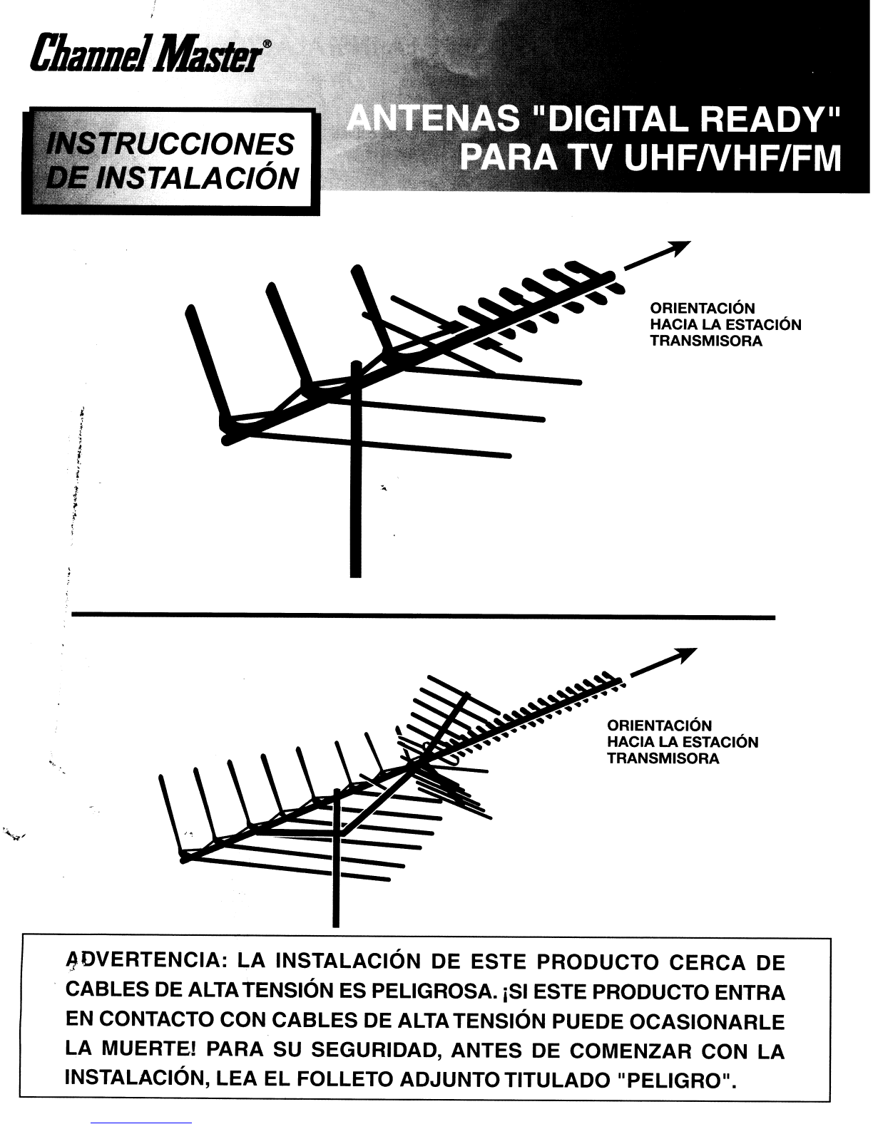
ORIENTACION
HACIA
LA
ESTACION
TRANSMISORA
i,
;
,
..
,
I.
f
.
~
ORIENTACION
HACIA
LA
ESTACION
TRANSMISORA
-
--
~DVERTENCIA:
LA
INSTALACION DE ESTE PRODUCTO
CERCA
DE
.CABLES
DE
ALTATENSION ES PELIGROSA. iSI ESTE PRODUCTO ENTRA
EN
CONTACTO CON CABLES
DE
ALTATENSION PUEDE OCASIONARLE
LA
MUERTEI PARA SU SEGURIDAD, ANTES
DE
COMENZAR CON
LA
INSTALACION,
LEA
EL FOLLETO ADJUNTO TITULADO
II
PELIGRO
II
•

CONSEJOS
SOBRE
LA
INSTALACION
HERRAMIENTAS QUE SERAN
DE
UTILIDAD
•Destornilladores de hoja grande ypequena
•
L1ave
inglesa
DONDE MONTAR
LA
ANTENA
•Corta cables
•Alicates
La antena puede montarse sobre la chimenea,
el
techo, una pared exterior 0la buhardilla. Seleccione
el
metoda
que mejor se adecua asu ubicaci6n en particular.
LINEA
DE
TRANSMISION
EI
cable coaxial de 75 Ohmios tiene una vida util mas prolongada que el cable bifilar plano de 300 ohmios yno se
ve afectado por
el
contacto con metales 0la humedad. Para instalar
el
cable coaxial, comience por conectar
el
extremo
del cable que corresponde
ala
antena al"balun" de la antena (provisto con la antena). Conecte los cables de entrada
del balun alas terminales
de
la antena. Luego, inserte el cable coaxial en
el
pit6n montado en el mastil. De este
modo, evitara que peso de la Ifnea desplace las conexiones de la antena. Apartir de este punto, el resto del cable
coaxial debe adherirse al mastil con cinta adhesiva.
Terminales
de
horquilla :J
(Conectelos alas terminales '1
VHF del televisor)
"
"Lenguetas de cable
.J
(Conectar alas terminale
SEPARADOR DE
75
OHMIOS UHF del televisor)
*
Unicamente
para
mode/os
de
te/evisores
antiguos
PROTECCION CONTRA RAYOS
EI
mastil yla Ifnea de transmisi6n deben contar con una conexi6n atierra para protecci6n contra rayos. Tienda un
alambre
#8
(0
mas grueso) de aluminio 0cobre desde un perno del mastil 0desde
su
base hasta una varilla de toma
atierra de 8'. Mantenga la Ifnea auna distancia respetable del cable de transmisi6n afin de evitar interferencias de
senales. Debe conectar un bloque de puesta atierra coaxial (Channel Master Modelo 3274) al cable de transmisi6n
de la antena en el punta en
el
que ingresa ala vivienda.
COMO ORIENTAR
LA
ANTENA HACIA
LA
ESTACION TRANSMISORA
Una vez finalizada la instalaci6n
de
la antena, encienda
el
televisor ysolicite que alguna persona controle la
recepci6n. En el techo, afloje las tuercas de los pernos en U y rote la antena hasta lograr la mejor recepci6n. Una
vez que
10
logre, ajuste firmemente las tuercas de los pernos en
U.
NOTA:
Si
las estaciones transmisoras
se
encuentran en diferentes direcciones, debera contar con
un
rotador de antena.
Este dispositivo
Ie
permitira girar la antena ycaptar estaciones individuales desde
el
interior de su casa. (Para obtener
mas informaci6n sobre los rotadores, consulte la Ifnea completa de rotadores de antena automaticos yprogramables
Channel Master).
Busque el tipo de instalaci6n que desea realizar en las siguiente paginas -
ilEA
lAS
INSTRUCCIONES PARA
El
MONTAJE
DE
lA
ANTENA EINSTAlACION ANTES
DE
COMENZAR
El
TRABAJO!
Su
vendedor
minorista
de
Channel
Master cuenta
con
todos
los
soportes
y
accesorios
que
necesita
para
realizar la instalaci6n.

MONTAJE EN
EL
ATICO
MONTAJE
ARRIOSTRADO
EN
TECHO
MONTAJE EN
CHIMENEA
MONTAJE EN
LA
PARED MONTAJE EN
TRipODE
'J
A - Montaje
en
techo B - Mastil C - Cable de trasmisi6n D - Pitones apresi6n E - Pitones arosca F - Cable
de
retenida
G - Anillo yabrazadera
de
retenida H - Pernos de anilla I - Flejes para montaje
en
chimenea J - Montaje
en
chimenea K - Montaje
en
tierra
L - Montaje
en
la
pared M - Montaje
en
tripode N - Soportes de inclinaci6n 0 - Tornillos de fijaci6n
MONTAJE
EN
LA PARED:
Limite de altura sugerido: 10 pies
por
encima de la azotea.
Si
la saliente del techo no es excesiva es posible utilizar
el
lateral
de la vivienda para realizar
el
montaje.
Si
el
montaje en la pared se
realiza de abajo hacia arriba, utilice un soporte de tierra con
un
"pico"
en la conexi6n de puesta atierra. Coloque los soportes para pared
sobre un esparrago si es posible, uno sobre el otro, con una
separaci6n minima de tres pies.
En
el
caso de los recubrimientos
metalicos, marque los orificios de montaje, luego perfore los orificios
guia atraves del recubrimiento para los tornillos de montaje.
Si
utiliza
un mastil de dos piezas, conecte las piezas como se indica,
asegurandose de que esten firmemente ajustadas. La divisi6n entre
los mastiles debe quedar entre los dos soportes de pared. Una vez
finalizada la instalaci6n, coloque en
el
mastil la ETIQUETA DE
ADVERTENCIA provistajunto con la antena iA LA ALTURA DE LA
VISTA!
MONTAJE
EN
TRipODE:
Se
utiliza para los techos
ados
aguas 0pIanos. Limite de altura sugerido: 10 pies
por
encima
de la azotea.
EI
montaje en tripode puede realizarse en cualquier tipo de techo,
ajustando
el
soporte en
la
pata central. Inserte
el
mastil en
el
soporte
del tripode ycoloque
el
soporte con las patas sabre las
vi
gas del
techo. Asegurese de que
el
mastil se encuentre en posici6n vertical.
Retire
el
recubrimiento protector de uno de los lados de los parches
de alquitran ycol6quelos debajo de cadauna de las patas del
tripode con
el
lado adhesivo hacia
el
techo. Ajuste
el
soporte de
tripode
al
techo par media de tornillos de fijaci6n. Una vez finalizada
la instalaci6n, coloque
en
el
mastilla ETIQUETA DE ADVERTENCIA
provista junto con la antena jA LA ALTURA
DE
LA VISTA!
REMOCION
DE
LA
ANTENA:
La
remoci6n de la antena debe realizarse siguiendo las instrucciones
de instalaci6n en sentido inverso. Para su seguridad, siga las
instrucciones para la instalaci6n de la antena comenzando par
el
ultimo paso.
Es
la unica manera segura de retirar la antena.
INSTALACION
EN
EL ATICO:
Con
un
soporte para techo, conecte
un
parte del mastil auna viga
del techo. Coloque yoriente la antena segun se describe para las
instalaciones en exteriores.
NOTA:
Las antenas no deben instalarse
en una buhardilla
si
el
techo 0las paredes son metalicos 0estan
forrados con aislamiento can refuerzo de laminas de aluminio.
MONTAJE
EN
TECHO:
Se
utiliza para los techos
ados
aguas
opIanos. Limite de altura sugerido:
10
pies
por
encima de la
azotea.
En
el
caso de montaje en techo, conecte
el
mastil con
el
anillo ylos
cables de retenida
al
soporte. Utilice tres 0cuatro cables de retenida,
separados adistancias iguales alrededor del mastil ysujete los
cables de retenida
al
techo 0aleros can pernos de anilla.
EI
anillo
de retenida debe estar colocado a 1 pie por debajo de la antena
aproximadamente. Coloque mezcla para techos alrededor de la
base del soporte, los tornillos ypernos de anilla como sellado anti-
humedad. Una vez finalizada la instalaci6n, coloque en
el
mastilla
ETIQUETA DE ADVERTENCIA provista junto con la antena iA LA
ALTURA
DE
LA VISTA!
MONTAJE
EN
CHIMENEA:
Limite de altura sugerido: 10 pies
por
encima de la azotea.
En
primer lugar, verifique la estabilidad de su chimenea afin de
asegurarse de que es
10
suficientemente firme como para sustentar
la antena en situaciones climaticas de vientos fuertes. No utilice una
chimenea que tenga ladrillos acementa sueltos. Instale
el
soporte
superior debajo de la linea superior de ladrillos y
el
soporte inferior
al
menos a
2V2
pies par debajo del soporte superior. (Para obtener
la maxima resistencia, separe los soportes tanto como sea posible.)
ADVERTENCIA:
LA
INSTALACION
DE
ESTE
PRODUCTO
CERCA
DE
CABLES
DE
ALTA
TENSION
ES
PELIGROSA.
PARA
SU
SEGURIDAD,
ANTES
DE
COMENZAR
CON
LA
INSTALACION,
LEA
EL
FOLLETO
ADJUNTO
TITULADO
IPELlGRO".
PRECAUCIONES IMPORTANTES Una vez finalizada la instalaci6n, coloque en
el
mastilla ETIQUETA
•Recuerde
que
cuando
trabaje sobre un techo
deben
DE
ADVERTENCIA provista junto con la antena
iA
LA ALTURA DE
emplearse
dos
personas.
LA
VISTA!
•
Nunca
camine sobre un techo
de
estuco cuando haya bajas
temperaturas.
•Utilice calzado deportivo 0suelas rugosas y
una
cuerda
de
seguridad.
•Siempre observe si existen cables
de
alta tension.
INSTRUCCIONES
PARA
EL
MONTAJE
DE
LA
ANTENA
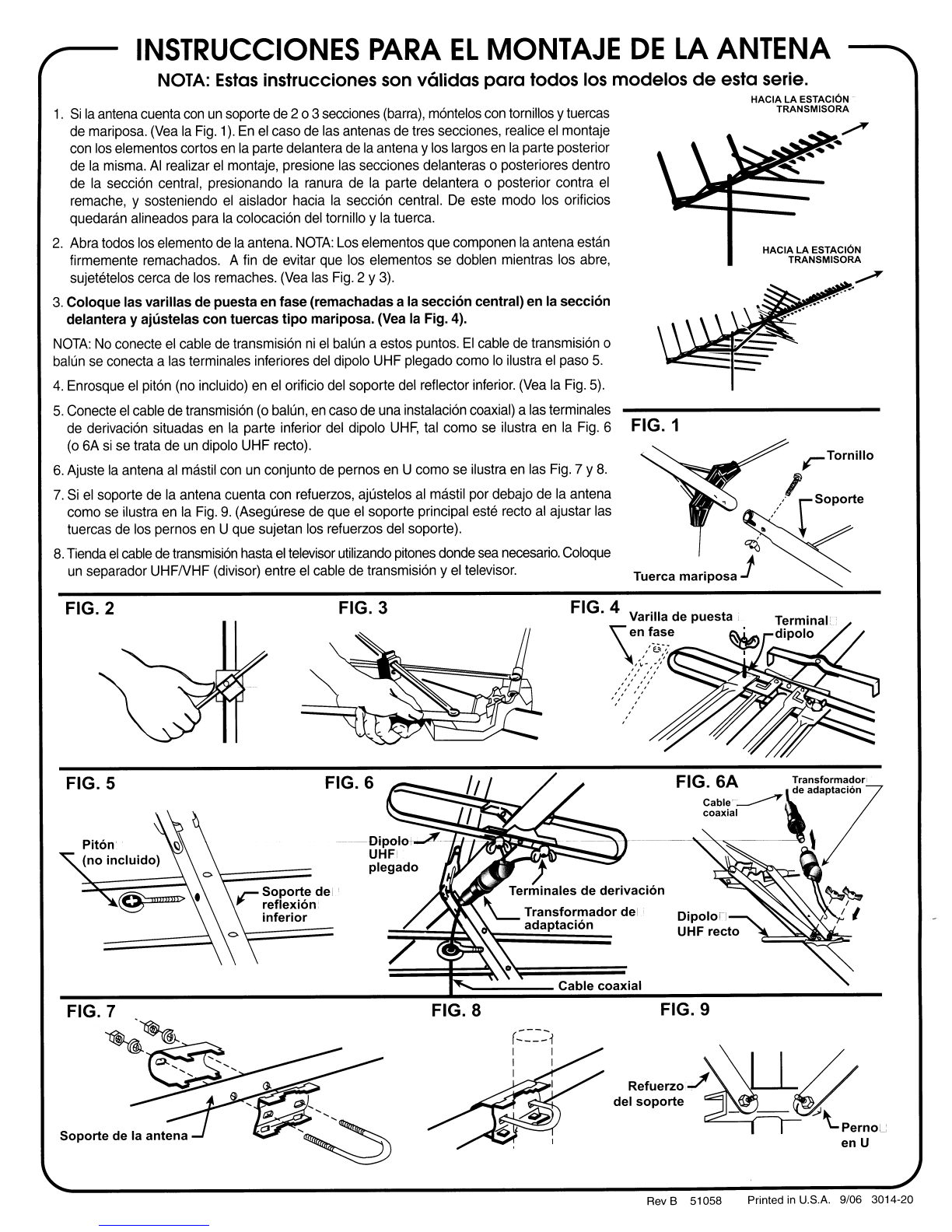
NOTA:
Estas
instrucciones son v61idas
para
todos los modelos
de
esta serie.
HACIA LA ESTACION
TRANSMISORA
HACIA LA ESTACION
TRANSMISORA
rTornillo
" .
/lrsoporte
~
Tuerca
mariposa
jV
~
FIG. 1
FIG. 9
Refuerzo..J'~~
del
soporte
- -
~
...
\..pernou
en
U
Cable
coaxial
FIG. 8
FIG. 6
FIG. 3
r
Soporte
del
reflexi6n
inferior
FIG. 2
FIG. 5
1.
Si
la
antena
cuenta
con
un
soporte
de
203
secciones
(barra),
m6ntelos
con
tornillos ytuercas
de
mariposa.
(Vea
la
Fig.
1).
En
el
caso
de
las
antenas
de
tres secciones, realice
el
montaje
con
los
elementos cortos
en
la
parte delantera
de
la
antena y
los
largos
en
la
parte posterior
de
la
misma.
AI
realizar
el
montaje, presione
las
secciones delanteras 0posteriores dentro
de
la
secGi6n
central, presionando
la
ranura
de
la
parte delantera 0posterior contra
el
remache, ysosteniendo
el
aislador hacia
la
secci6n central.
De
este modo los orificios
quedaran alineados para
la
colocaci6n
del
tornillo y
la
tuerca.
2.
Abra todos
los
elemento
de
la
antena.
NOTA:
Los elementos
que
componen
la
antena estan
firmemente remachados. A
fin
de evitar
que
los
elementos
se
doblen mientras los
abre,
sujetetelos cerca de
los
remaches.
(Vea
las
Fig.
2 Y
3).
3.
Coloque
las
varillas
de
puesta
en
fase
(remachadas
ala
secci6n
central) en la
secci6n
delantera y
ajlistelas
con
tuercas
tipo
mariposa. (Vea la Fig. 4).
NOTA:
No
conecte
el
cable
de
transmisi6n
ni
el
balun
aestos puntos.
EI
cable
de
transmisi6n 0
balun
se
conecta a
las
terminales inferiores
del
dipolo
UHF
plegado como
10
ilustra
el
paso
5.
4.
Enrosque
el
pit6n (no incluido)
en
el
orificio
del
soporte
del
reflector inferior.
(Vea
la
Fig.
5).
5.
Conecte
el
cable
de
transmisi6n (0 balun,
en
caso de
una
instalaci6n coaxial) a
las
terminales
de
derivaci6n situadas
en
la
parte inferior
del
dipolo
UHF,
tal
como
se
ilustra
en
la
Fig.
6
(0
6A
si
se
trata
de
un
dipolo UHF recto).
6.
Ajuste
la
antena
al
mastil
con
un
conjunto
de
pernos
en
Ucomo
se
ilustra
en
las
Fig.
7 Y
8.
7.
Si
el
soporte de
la
antena cuenta con refuerzos, ajustelos
al
mastil por debajo de
la
antena
como
se
ilustra
en
la
Fig.
9.
(Asegurese
de
que
el
soporte principal
este
recto
al
ajustar
las
tuercas
de
los
pernos
en
U
que
sujetan
los
refuerzos
del
soporte).
8.
Tienda
el
cable
de
transmisi6n
hasta
el
televisor
utilizando
pitones
donde
sea
necesario.
Coloque
un
separador UHFNHF (divisor) entre
el
cable
de
transmisi6n y
el
televisor.
Rev B51058 Printed
in
U.S.A. 9/06 3014-20
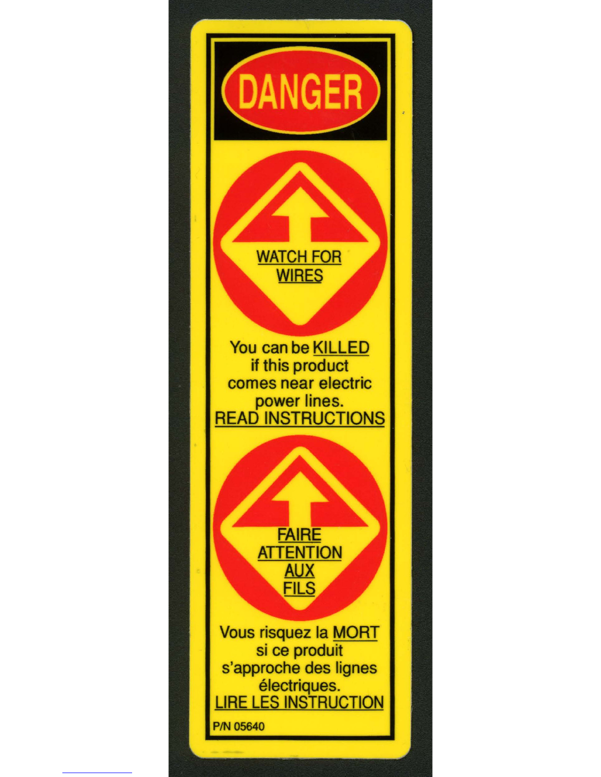
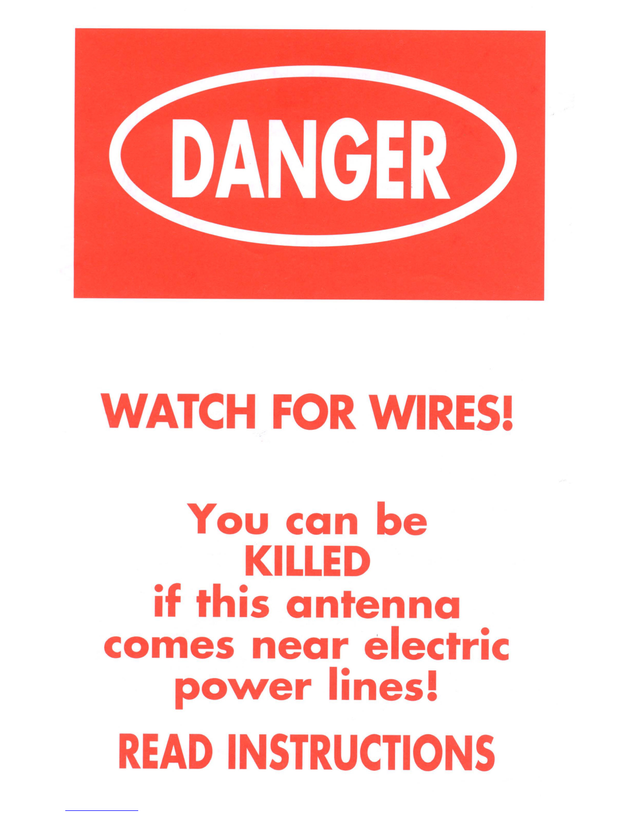
WATCH
FOR
WIRES!
You
can
be
KILLED
if
this
antenna
comes
near
electric
power
lines!
READ
INSTRUCTIONS

iCUIDADO
CON
LOS
CABLES!
iSi
esla
anlena
enlra
en
conlac-
10
con
cables
de
0110
lension
puede
ocasionarle
10
MUERTEI
LEA
LAS
INSTRUCCIONES
TELEVISION
ANTENNA
PRODUCTS
LIMITED
NINETY
(90)
DAY WARRANTY
This
CHANNEL
MASTER' product
is
warranted
to be free from defects
in
material
and
workmanship under normal
use
and service. CHANNEL
MASTER
sholl repair or replace
defective product,
at
no
charge,
or
at
its
option,
refund the purchase price, if the
product
is
returned
10
CHANNEL
MASTER
not more than ninety (90) doys ofter purchase. Removal or
replacement
of
product
and
its transportation shall not be the cost
of
CHANNEL
MASTER
except
CHANNEL
MASTER
shall return repaired
or
replaced equipment freight
prepaid.
This
Warranty
sholl not
apply
to product which has been repaired
or
altered in
any
way
so
as to affect
is
stability or durability, nor which has been subject to misuse, negligence
or
acci-
dent,
This
WarTanty
does
not
cover
product which
has
been
impaired by
severe
weather
can·
di:ions
such
as
excessive
wind,
ice,
storms,
lightning, or other natural occurrences over which
CHANNEL
MASTER
has
no
control, nor sholl
this
Warranty apply
to
product which
has
been
operated
or
installed other
than
in
accordance with
the
instructions furnished by CHANNEL
MASTER
Claimants under
this
Warranty sholl
present
their claim along with
the
defective product
to
CHANNEL
MASTER
immediately upon failure. Non-eompliance with any port of
this
claim
procedure
may
invalidate
this
Warranty
in
whole or
in
part.
THIS
WARRANTY
IS
EXPRESSLY
IN
LIEU
OF
All
OTHER
AGREEMENTS
AND
WARRANTIES,
EXPRESSED
OR
IMPLIED,
INClUDING
BUT
NOT
LIMITED
TO
THE
IMPLIED
WARRANTIES
OF
MERCHANTABILITY
AND
FITNESS
FOR
A
PARTICULAR
PURPOSE.
CHANNEl
MASTER
DOES
NOT
AUTHORIZE
ANY
PERSON
TO
ASSUME
FOR
IT
THE
OBLIGATIONS
CONTAINED
IN
THIS
WARRANTY
AND
CHANNEL
MASTER
NEITHER
ASSUMES
NOR
AUTHORIZES
ANY
REPRESENTATIVE
OR
OTHER
PERSON
TO
ASSUME
FOR
IT
ANY
OTHER
LIABILITY
IN
CONNECTION
WITH
THE
PRODUCT
DELIVERED
OR
PROVIDED
IN
NO
EVENT
SHAll
CHANNEL
MASTER
BE
LIABLE
FOR
ANY
lOSS
OF
PROFITS,
LOSS
OF
USE,
INTERRUPTION
OF
BUSINESS,
OR
INDIRECT,
SPECIAL
OR
CONSEQUENTIAL
DAM-
AGES
0'
ANY
KIND
In
no
event
shali
CHANNEL
MASTER
be
liable
for
damages
in
on
amount greater
than
the
purchase price of
the
equipment
WATCH
FOR
WIRES!
You
can
be
KILLED
if
this
antenna
comes
near
electric
power
lines!
READ
INSTRUCTIONS
;Yww
chonnelmoster com
©2002
Chonnel
Moster
llC (95950)
Rev
E
EeN
9007149
Printed
in
USA
PRODL!CTOS
PARA
ANTENA
DE
TELEVISI6~
GARANTIA L1MITADA
POR
NOVENTA
(90)
DIAS
Se
gorontiz~
que
esfe
produ~to
CHANNEL
MASTER® carece
de
defectos
de
mate-
flales y
fabrlcaci6n
en
condiciones
de
uso y
servicio
normales.
CHANNEL
MASTER
repararo
0
reemplazaro,
sin costo
alguna,
los
produclos
que
presenten
defectos
0,
a
su
discrecion,
reembolsaro
el
precio
de
com
pro
si
el
producto
es
devuelto
~
CHANNEL
MASTER 0mas
tordor
novento
dias
f?Oj despues
de
10
com·
pro
EI
retlra 0
reemplozo
del
producto
yel transporte
del
mlsmo
no
estoro a
cargo
de
CHANNEL
MASTER
salva
que
CHANNEL
MASTER
devuelva
equipas
reparados
0
de
reemplozo
con transporte
prepago.
Esto
garantia
no
se
aplico
0los
produdos
que
hayan
sida
reparodos
0
olterados
de
manera que afecte
su
estabilidod
0
durabilidad,
ni
que
hayon
sido
objeto
de
r~al
usa,
negligencia
0accidentes.
Esta
gar.anlla
no
cubre los productas
que
hayon
sldo
danados
por
condiciones
meteorologlcos
adversas
como
el viento excesivo,
el hielorlos tormentas, los rayos u
olros
fem6menos
climalicos
naturales fuera
del
control
de
CHANNEL
MASTER, ni
de
aplicaro
alos productas
que
hayon
sido
ulilizados
0instalados
de
un
modo
que
no
coincida
can las instrucciones provistas
por CHANNEL
MASTER.
Aquellas personas
que
deseen
realizer
redamos
en
virlud
de
esta
gorantio,
deberan
presenter
su
reclamo
junto can el
prod
ucla
defecfuoso a
CHANNEL
MASTER
inmedialamente
despues
de
10
aporici6n
de
10
folia.
EI
incumplimiento
de
cualquier
parle
de
este
procedimiento
para
10
presentacion
de
redamos
anularo
10
garontio
en forma total 0
parcial.
ESTA
GARANTiA
REEMPLAZA
EXPR,ESAMENTE
TODOS
LOS
DEMAs ACUERDOS
yGARANTIAS,
~XPRESQS
0IMPlICiTOS,
INClUYENpO,
PERO
SIN
lIMITARSE,
A
LAS
GARANTIAS
IMPLICITAS
DE
COMERCIALIZACION YADAPTACION
PARA
UN
FIN
DETERMINADO. CHANNEL
MASTER
NO
AUTORIZA ANINGUNA,PER-
SONA
A
ASUMIR
LAS
OBLIGACIONES CONTENIDAS
~N
ESTA
GARANTIA Y
CHANNEL
MASTER
NO
ASUME NI AUTORIZA A
NINGUN
REPRESENTANT~
U
OTRA
PERSONA
A
ASUMIR
NINGUNA
OTRA
RESPONSABILIDAD
EN
RELACION
CON
EL
PRODUCTO ENTREGADO 0SUMINISTRADO
Ei:'I
NINGUNA
CIRCUNSTAN<;IA CHANNEL
MASTER
SERA
,RESPONSABLE
DE
PERDIDAS
DE
GANANCIAS,
PJ:RDIDA
DE
USO, INTERRUPClON
DE
LAS
ACTIVI-
DADES
COMERCIALES NI
DANOS
INDIRECTOS,
ESPECIALES
0
CONSECUENTES
DE
NINGUNA
NATURALEZA.
En
ningun coso
CHANNEL
MASTER
s.era
responsoble
de
danos
per
un monto
superior
01
precio
de
com
pro
del
equlpo
iCUIDADO
CON
LOS
CABLES!
iSi
esta
antena
entra
en
con
tac-
to
con
cables
de
alta
tension
puede
ocasionarle
10
MUERTEI
LEA
LAS
INSTRUCCIONES
\~'l2002
Channel Moster
lLC
195950)
Rev.
E
ECN
9007149
Impreso en
EE.UU

WARNING!
Installation
of
this
product
near
power
lines
is
dangerous.
For
your
safety,
follow
the installation
directions.
Before
you
start installation, let
us
warn
you
of
the
danger
of
letting
any
part
of
your
antenna
system
touch electrical
power
lines - -
you
may
be
killed.
It
happens
more
often than
you
realize!
Someone falls
off
a
roof
or
gets the shock
of
his life.
Unfortunately, a
good
antenna
site
is
often
near
electrical
power
lines.
If
any
metal
antenna
part
touches a
powerline,
it completes
an
electrical
path through the installer (that's you).
iADVERTENCIAI
La
instalacion
de
este
producto
cerca
de
cables
de
alta tension
es
peligrosa.
Para
su
seguridad,
siga las instrucciones
de
instalacion.
Antes
de
comenzar
la instalacion,
permitanos
advertirle
acerca
del
peligro
de
que
el
sistema
de
la
antena
entre en
contacto con cables
de
alta
tension,
ya
que
pod
ria
ocasionarle
la muerte.
iOcurre
mas frecuentemente
de
10
que
usted cree!
Alguien
cae
de
un
techo 0
recibe una
tremenda
descarga.
Lamentablemente,
un
buen
lugar
para
la
instalacion
de
una
antena
a
menudo
se
encuentra cerca
de
cables
de
alta
tension.
Si
alguna
parte
metalica
de
la
antena entra
en
contacto
con
un
cable
de
alta tension,
se
completa
el
recorrido
electrico atraves del
instalador
(es
decir, usted).
FOLLOW
THESE
RULES
AND
LIVE:
1Perform as much
antenna
assembly
on
the
ground
as possible.
2. Watch out for overhead
power
lines. Check the distance to the
power
lines
;seiO{WlCE
¥H~
~~~III~BM
l~g~Cg~~~NfNW~JIAXS~l~~l~XAY
FROM
All
POWER
LINES.
3.
Do
not
use
ametal ladder.
4.
Remember, even fhe slightest touch
of
an antenna
10
a
power
line can cause
afatal shock.
5.
Don't try to do the job on awindy
day
6
Have
a
friend
as aspotter
when
you're
on
the roof. They
can
see things
you can't.
7. If
you
start to
drop
an antenna, get
awoy
from it
and
lei
it
fall.
8. If
any
part
of
the
antenna
should
come
in
contact
with
a
power
line -
CAll
YOUR
lOCAL POWER COMPANY; DON'T
TRY
TO
REMOVE
IT
YOURSELF
IThey'll remove
it
safely.
9.
Mast,
lead-in
and
metal
guy
wires
are
excellent
conductors
of
electrical
currenl
-
keep
them
away
from
power
lines too.
10.
Be
sure
your family and friends understand
the
danger of touching an
overhead
power
line.
Tell
them
never
to try to remove
any
object
in
contact
with
a
power
line
-CB,
TV
antenna
or
anything
else
11
Make
sure that the antenna mast assembly
is
properly grounded
AND,
IF
AN ACCIDENT SHOULD OCCUR WITH
THE
POWER LINES:
Don't grab. hold
of
aperson
in
contact with the antenna
and
power
line
(you'll get
,t
too).
2.
Use aDRY
board,
stick
or
rope
to push
or
pull the
antenna
away
from the
victim
3.
If the
victim
has
stopped
breathing,
administer
artificial
respiration
and
stay
with
it.
4. Have someone call for medical help
Recommended
by
the
National
Consumer Product Safety Council.
IMPORTANT
GUIDELINES FOR
INSTALLING
ANTENNAS:
If
you're not sure
about
careful, safe installation -
don't
try
to
do
it yourself Call
for professional help (Yellow Pages under Television Antenna Systems or your
local
power
company).
Measure
the
maximum length
of
the antenna
and
mast assembly
and
then stay at
least twice that distance
away
from
power
lines.
(If
you
don't
have at leas! this
much space, get aprofessional to
do
the job.
For mast support,
use
only
1 1
\4"
diameter or larger antenna most sections.
Lengths over
10
feet should be guyed at least each
10
foot section
CUMPLA
CON
LAS
SIGUIENTES REGLAS YCONSERVE
SU
VIDA:
Realice
10
mayo!
porte
de
las
toreas
de
montoje
de
10
unteno
en el
piso
Cuidese
de
los
cables
oereos
de
alta
tension.
Verifique
10
distoncio
que
10
seporo
de
los
cables
de
alta
tension antes
de
iniciar
10
instolocion
~
lE
RECOMENDAMOS
QUE
SE
MANTENGA
A
UNA
DISTANCIA
MiNIMA
DE
lOS
CABLES
DE
ALTA
TENSION
IGUAl
AL
DOBLE
DEL
LARGO
DEL
CONJUNTO
DE
LA
ANTENA
No
uti
lice
uno
escolero
metolico.
Recuerde
que
hosta
el
contocto
mas leve entre
10
anteno
ylos
cables
de
alta
tension
pueden
provocor
uno
descargo
mortal.
5.
No
intente
realizar
esto
torea
en
un
dio
ventoso.
6.
Cuente
can
10
presencia
de
otro
persona
pora
que
10
observe
mientros
S0
encuentro
en
el techo. Eslo
persona
puede
ver
cosas
que
usted
no
ve
7.
Si
10
anlena
comienzo
a
coerse,
olejese
y
dejela
coer
8Si
cuolqujer
porte
de
10
onteno
entrq
~n
contocto
can
un
coble
de
alto
tension -
COMUNIQUESE
CON
SU
COMPANIA LOCAL
DE
ElECTRICIDAD,
,NO
INTENTE
RETlRARLA USTED
MISMO!
Elias
10
retiroran
de
monera
segura
9
EI
mastil, los
cables
de
acometido
ylos
cables
melelicos
de
retenido
son excelentes
conduclores
de
10
corriente
eleclrica
-
mantengalos
alejados
de
los
cables
de
0110
lension
10
Asegurese
de
que
sus
familiores
y
amigos
comprendan
el
peligro
que
implico
locor
un
coble
oereo
de
alta
lensiOn.
Digales
que
nunca
intenten
retirar
ningun
objeto
que
se
encuentre
en
contacto
con
un
cable
de
alta
tension -una
anlena
de
CB,
de
TV
0
cualquier
otro
elemento
11
Asegurese
de
que
el
conjunto
del
moslil
de
10
onleno
cuente
can
uno
conexion
a
lierro
odecuada
Y
EN
CASO
DE
QUE
OCURRA
UN
ACCIDENTE
CON
LOS
CABLES
DE
ALTA
TENSION:
1.
No
toque a
10
persona que
se
encuentro
en
conloclo can
10
onlena y
el
cable de alta tension
(Ie
ocurrir6
10
mismo 0
usted)
2. Utilice uno tablo, varo acuerda SECA para olejar
10
antena de
10
victima.
3.
Si
10
victima ha
dejado
de
respirar, odministre respiracion artificial ypermanezca a
su
lado
4. Solicite mistencio medico.
Recomendado par el
Camejo
Nocionol
de
Seguridad
de
Productos para Cansumo
PAUTAS
IMPORTANTES
PARA
LA
INSTALACION
DE
ANTENAS:
Si
no esta segura acerca
de
como realizar una instalacion
cuidadosa
ysegura -no intente hoc-
erlo usted mismo. Solicite
ayuda
profesiona(
{en
las Paginas Amarillas, en
10
seccion
de
Sistemas
de
Antenas de Television aen
su
campania
de
electricidad local).
Mida
10
longitud maxima del canjunto
de
antena ymastil yluego alejese
01
menos el
doble
de
esa distancia
de
los cables
de
alto
ten.siOn.
lSi no cvento can
ese
espacio, contrate a
un
profe.sional
para
realizer
10
tareo)
Para sostener el masli(, utilice unicomenle soporles
para
mastiles de antenos
de
un diometro
de
1
l/4"
asuperior.
las
longitudes superiores a10 pies deben arriostrarse can cables
01
menos
coda
10 pies

WHERE TO INSTALL YOUR ANTENNA
(SITE
SELECTION): TYPES
OF
SUPPORT
STRUCTURES
AND
MOUNTING
Not
Recommended.
For
Professional
Use
Only.
Not
Recommended.
For
Professional
Use
Only.
Before attempting
to
install
your
antenna, think
where
you can best place
your
anfenna for safety
and
performance.
To
determine asafe distance from wires,
power
lines,
and
trees:
1Measure the height
of
your antenna
2.
Add
this length to the length
of
your
tower
or
most,
and
then
3. Double this total for the minimum recommended safe distance.
If you
ore
unable to maintain this safe distance, STOP! GET PROFESSIONAL
HELP.
Most antennas
ore
supported
by
pipe
masts anached to the chimney, roof,
or side of the house. Generally, the higher the
antenna
is
above
ground, the bet·
ter it performs.
Good
practice
is
to install
your
vertical antenna
about
5to
10
feet
above
the
roof
line
and
as far
away
as possible from
power
line
and
obstructions.
DESCRIPTION
Tripod Mount
Roof
Mount
Wall Mount
Chimney
Mount
Tower
Telescoping
Masting
USAGE
Peaked and Flat
Type
Roofs
Peaked and
Flat
Type
Roofs
Side of Structure
Chimney Only
HEIGHT
LIMITATION
10
Feet
above Roohop
10
Feet
above Roohop
10
Feel
above Roohop
10
Feet
above Chimney
Top
D6NDE
INSTALAR
LA
ANTENA (SELECCI6N
DE
LA
UBICACI6N):
NOTE: IF
ANTENNA
IS
MOUNTED HERE OR HERE...
.---
/THE
SAFE DISTANCE FROM
POWER LINES
SHOULD
BE
TWICE THE HEIGHT OF THE
MAST
PLUS THE HEIGHT
OF THE ANTENNA
SAFEST
LOCATION
TIPOS
DE
ESTRUCTURAS
DE
SOPORTE YMONTAJE
Monlaje
en
paredes
Lateral
de
la
eslruclura
Montaie
en
chimenea Unicamente
en
chimeneas
Antes
de
intentar instalar
10
antena, piense
d6nde
puede colocarla
para
obtener
10
mayor seguridad yel meior desempeno.
Afin
de
determiner una distancia segura
de
105 cables, cables
de
alta tension y
arboles:
1.
Mido
10
altura
de
10
antena
2. Sume
dicha
longitud a
10
longitud
de
10
torre amastil, yluego
3. Duplique esta longitud
para
obtener
10
distoncio
de
seguridad minima recomen·
dada.
Si
no
Ie
es
posible mantener esta distancia
de
seguridad, jDETENGASE! SOLICITE
AYUDA PROFESIONAL.
La
mayoria
de
las antenas estan sostenidas
par
mastiles
de
cano que
se
ajuston alas chimeneas,
01
techo 0alas paredes laterales
de
la vivienda.
En
general, cuanto mas
alejada
del suelo
se
encuentra
10
antena, mejores resultados
obtendra. Una practico recomendable
es
instalar
su
antena vertical entre 5y10 pies
por
encima
de
10
linea del techo y
10
mas leios posible
de
los cables
de
alta tension y
los obstaculos.
DESCRIPCION
Montaje
en
tripode
Montaje
en
techo
Torre
M6stil
telesc6pico
USO
ALTURA
Techos
ados
aguas
0
pianos
10
pies
par
encima
de
la
azotea
Techos
ados
aguas
0
pianos
10
pies
par
encima
de
10
azolea
10
pies
par
encima
de
la
azotea
10
pies
par
encima
del
final
de
la
boca
de
la
chimenea
No
se
recomienda.
Unicamente
para
usa
profesional.
No
se
recomienda.
Unicamente
para
uso
profesional.
NOTA:
SI
lA
ANTENA SE
COlOCA
AQUi 0
AQUL
~
.
lA
DISTANCIA DE SEGUFjIDAD
DE
lOS
~
~
CABLES
DE
ALTA TENSION DEBE
~~~
iJl't,.~lA~f~~k~~iu~~
ALTURA
DE
lAANTENA
UBICACI6N
MAs
SEGURA

"UNIVERSAL"
ROOF MOUNT
ROOF MOUNTING:
The swivel feature
of
"universal"
type mounting brackets makes
a
convenient
antenna
mount
for
flat
or
peaked
raafs.
One
clamp
type bracket
is
used with 3or 4
guy
wires equally
spaced
around the mast
and
anchored
10
the
roof or eaves
by
eyebolts.
Installations involving atripod
mount
and
amast should
be
guyed
if
the mast
is
ten feet
or
more.
Tripod
mount must
be
securely
anchored
to the
roof
as
should the
guy
wires.
Apply
roaling
campaund
araund
the base
of
the bracket, screws
and
eyebolts for moisture sealing.
HOW
TO
INSTALL
YOUR ANTENNA
1. Assemble your
new
antenna
on the
ground
in
accordance
with
separate
assembly instructions supplied
with
it.
2.
On
the
ground,
damp
antenna
to mast, pull
enough
transmission
line
to con-
nect to antenna.
3. Install selected mounting bracket.
4.
If
you
are
going
to use
guy
wire
installation instead
of
amounting bracket:
•install
guy
anchor
bolts
•estimate length
of
guy
wire
and
cut
•attach to mast using
guy
ring
5.
Mount
the extra
"Warning
Label"
supplied
in the
hardware
bag
on
the anten-
na mast
at
eye level after installation has been
completed.
ANTENNA REMOVAL
Removal
of
the
antenna
should
be
exactly
the reverse
of
the installation instruc-
tions. Please, for
your
own
safety,
follow
the instructions for installing
the
antenna
starting
with
the last step first. That's the
only
safe
way
to remove an
antenna.
LIGHTNING PROTECTION
SIDE
OF HOUSE MOUNTING:
Where
roof
overhang
is
not
excessive, the side
of
the house
provides
aconvenient mounting. Position
the brackets over astud
if
possible,
one
above
the other,
and
space
two
or
three feet
apart. For metal siding, first mark mounting holes,
then
drill
pilol
hales
thraugh
the
siding
to
accept
mounting screws.
To
protect
your
house
and
your
TV
(FM,
CB,
etc....)installation, the mast
of
your
antenna system must
be
properly
grounded.
Drive a4' .
8'
ground
rod
as close
as
possible to the
antenna
supporting
structure
or
antenna
base. Then
connect
a
#8
(or
largerl
copper
or
aluminum
wire
between the base
of
the
antenna
and
the
ground
roa. Also, an
antenna
discharge
unit (sometimes referred to
as
a
lightning
arresler) should
be
connected to the antenna lead-in
at
the
place
where
it enters the home. /Follow the instructions
provided
with
the static
discharge
unit.)
WALL
MOUNT
300
ohm
Transmission
Line
Ground
Wire
from
mast
ANTENNA DISCHARGE UNIT
The
chimney
is
often an easy
and
convenient
mounting place. But the
chimney
must
be
strong
enough
to
support the antenna in high winds. Do
"-
not
use
achimney that has loose bricks
or
mortar.
A
good
chimney
mount makes
use
of
a 5
or
10
foot 1 1
\4"
diameter
steel mast,
and
aheavy-
duty
two
strap
clamp-type
bracket.
Install
the
upper
bracket just
below
the
top
course
of
bricks,
and
the
lower
bracket
two
or
three feet
below
the
upper
bracket. For maximum strength, space the
brockets as much as possible. Antenna Discharge Unit
ground
wire
CHIMNEY
MOUNTING:
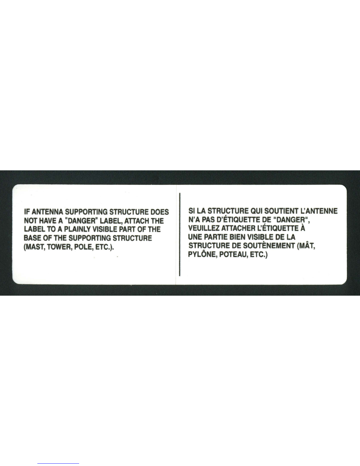
NOTE:
Mount
the extra
"Warning
Label" supplied
with
the
antenna
hardware
to
the mast
at
eye level after installation has been completed.
Cable de
conexi6n
atierra
de la
unidad
de
descarga
de
la antena
UNIDAD
DE
DESCARGA
DE
LA
ANTENACable
de
conexi6n
Linea
de
atierra del rnastil
transmisi6n
de
,-
,,300ohmios
'r==-"'II~
atierra
REMOCION
DE
LA
ANTENA
La
remocion
de
10
antena
debe
reolizarse
siguiendo
las instrucciones
de
insta-
lacion
en sentido inverso. Par
su
seguridad,
siga las instrucciones
para
la insta-
ladon
de
la antena
comenzando
por
el ultimo paso.
Es
10
unica
manera
segura
de
retirar
10
antena.
PROTECCION CONTRA RAYOS
1.
Monte
su
nueva antena en el piso
de
acuerdo
con las instrucciones
de
mon-
taje
provistas.
2.
En
el piso, ajuste la antena
al
mastil,
prepare
una
longitud
suficiente
de
linea
de
transmision
para
conectarla
a
10
antena.
3.
Instale el soporte
de
montaje
seleccionado.
4.
Si
desea
utilizar
cables
de
retenida en
lugar
de
un soporte
de
montaje:
•instale pernos
de
anclaje
de
retenida
•
calcule
la
lan.9itud
del
cable
de
retenida ycartela
•ajustelo
01
mostil
con
un
anillo
de
retenida
s.
Una
vez
finalizada
la
instalacion,
coloque
en
el
mastil
la
eti~ue·
ta
de
advertencia
provista
iunto
con
la
antena,
a
la
altura
de
la
vista.
Para
proteger
su
vivienda
y
su
instalocion
de
TV
(FM, CB, etc....
),
el mastil
del
sistema
de
antena
debe
contor
con una
conexion
atierra
adecuoda.
Coloque
una
varilla
de
conexi6n
atierra
de
4'
a
8'
10
mas cerca
posible
de
10
estructura
de
soporte
de
10
antena
0
de
la base.
luego,
coloque
un
alambre
#8
10
mas
grueso)
de
atuminio
0
cobre
entre la base
de
la antena yla
varilla
de
conexion
atierra. Tambien
debe
conectar
una
unidad
de
descarga
de
10
antena
la
menudo
denominado
supresor
de
rayos)
al
cable
de
acometida
de
la
anlena,
en
el
lugar
en el
que
ingresa ala
vivienda.
(Siga las instrucciones provistas junto
con
fa
unidad
de
descarga
de
est6tica).
COMO
INSTALAR
LA
ANTENA
:--::---
MONTAJE
EN
CHIMENEA
Cuando
10
saliente del techo no
es
excesiva,
10
pared laleral
de
10
vivienda
es
un
lugar de montaie adecuado.
De
ser
posi~
ble, coloque los soportes sobre
un
esparrago, uno sobre el
olro, con una separacion de dos 0
tres
pies.
En
el coso
de
los
recubrimientos metalicos, primero marque
los
orificios
de
mon-
taje, luego perfore los orificios guia atroves del recubrimiento
para cotocar los tornillos
de
monloie.
MONTAJE
EN
LA
PARED
LATERAL
DE
LA
VIVIEN·
DA:
MONTAJE
EN
TECHO:
La
coracteristico girotorio
de
los
soportes
de
montaje "universales"
hoce
que
sean
un
tipo de montaje
odecuado para
lechos
ados
aguos 0
pIanos.
5e
utiliza
un
soporte
de
tipo
abrazodera
con
304cables
de
retenida colocados 0distancios
equiv-
olentes
olrededor
del
mastil
y
sujeta·
dos
01
techo
0alerc por medio
de
pernos
de
onilla.
Las
instalaciones
con
un
soporte
de
tripode y
un
mastil
deben arrioslrorse
si
el
mas
til
tiene
diez 0
mas
pies
de
altura.
EI
soporte
de
trfpode debe
sujelorse
firmemente
01
techo
01
igual
que
los
cables de retenida.
Aplique
mezcla
para
techos
alrededor
de
10
base
del
soporle,
los
lornillos y
pernos
de
anilla para lograr
un
sella-
do anti·humedad.
MONTAJE
EN
LA
PARED
MONTAJE
EN
CHIMENEA:
NOTA:
Una
vez
finalizada
la
instalacian, calaque
en
el
mastilla etiqueta de
advertencio
provista
junto
con
10
antena,
a
10
altura
de
10
vista.
A
menudo,
to
chimeneo
es
un
lugar convenienle y
sencillo
para realizar
el
mon/aie.
Pero
10
chimenea debe
ser
10
suficienlemenle
resislenle
como pora
sostener
10
antena
en
coso
de
vienlos
fuertes.
No
utilice
uno
chimenea
que
tenaa
ladrillos 0
cementa
flojo.
"-
Para
realizer
un
buen
montoie
en
chimenea debe ulilizarse
un
mastil
de
acero 5010
pies
y1 1
\4"
de
diametro,
~
asi
como
un
soporte
de
tipo abrazadera
con
dos
flejes
de
alto
resislencia.
Inslate
el
soporle superior debajo
de
10
linea superior
de
ladrillos y
el
soporte
.inferior
01
menos
2
o 3
pies
por debalo
del
soporle
supenor.
Para
oblener
10
maxima
resistencia,
separe
los
soporles
tonto
como
sea
posible
MONTAJE
"UNI·
VERSAL"
EN
TECHO
Other manuals for Digital ready
1
Table of contents
Other Channel Master TV Antenna manuals

Channel Master
Channel Master Advantage 3016 User manual

Channel Master
Channel Master CM-1776 User manual

Channel Master
Channel Master 100 User manual

Channel Master
Channel Master CM-3000HD User manual

Channel Master
Channel Master Off-Air Antenna User manual

Channel Master
Channel Master CM-7779HD User manual

Channel Master
Channel Master CM-3202 User manual

Channel Master
Channel Master 1 TV User manual

Channel Master
Channel Master FLATenna User manual


