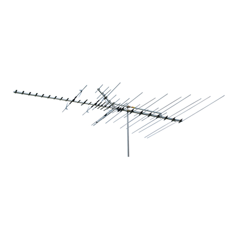
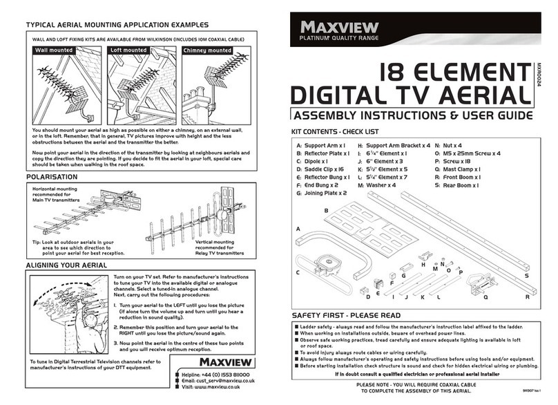
Channel Master Off-Air Antenna User manual

Installation
Off-Air Antenna
Guide
Solutions For
The Professional Installer

INTRODUCTION
INTRODUCTION
1
The information in this manual has been
gathered from some of the most experienced
antenna installation professionals in the
country and compiled by Channel Master®field
engineers. It is intended for technicians who are, or
plan to become professional antenna installers. Any
handy “do-it-yourself” consumer can mount an
antenna, run transmission line and pull in some kind
of a signal. But only a professional can select and
precisely install the correct antenna and assure his
customers years of superior TV/FM reception.
Back in the 1940s, TV antennas were actually
manufactured by hand at the installation site. Each
antenna was assembled, piece by piece, at the
customer’s home. Channel Master eliminated this
time-consuming labor by introducing the first
preassembled TV antenna, providing excellent
reception in all areas and at reasonable prices.
Today medium-to-high gain, broadband antennas are
essential for good reception. Even the most expensive
color TV or FM stereo receiver can’t perform to full
potential without the strong signals that only a
quality antenna system can provide.
Advanced antenna theory and design is not included
in this manual. The greatest emphasis is on practical,
time-tested methods and procedures for properly
installing TV and FM antennas. With this foundation
of knowledge, you can build your reputation as a
professional antenna installer–one who is capable of
assuring his customers the finest performance from
today’s sophisticated TV and FM equipment.
A WORD ABOUT ANTENNA SPECIFICATIONS
Sensitivity ratings are based on optimum conditions
over unobstructed terrain. What lies between a trans-
mitter and an antenna installation will have a direct
bearing on what type of antenna is appropriate.
Factors to consider are: the power output and height
of a transmitting antenna tower, the type of terrain
between the tower and the receiving antenna, and the
size and number of buildings that lie in the path of the
transmission.
All Channel Master VHF/FM and UHF/VHF/FM
antennas have sensitivity classifications such as
“fringe,” “suburban,” “deep fringe,” etc. These classi-
fications are designed to indicate at what distance
from a TV transmitter the antenna will provide the
best reception. Our antenna lab has computed the
following chart as a general guide:
Area Designation For VHF For UHF
Deepest Fringe 100+miles 60+miles
Deep Fringe 100 miles 60 miles
Fringe 80 miles 45 miles
Near Fringe 60 miles 40 miles
Far Suburban 50 miles 35 miles
Suburban 45 miles 30 miles
Far Metropolitan 30 miles 25 miles
Metropolitan 25 miles 15 miles
Additional performance information is available from
Channel Master upon request. Write to:
Channel Master
P.O.Box 1416
1315 Industrial Park Drive
Smithfield,NC 27577
Or contact us through our site on the World Wide
Web at:
www.channelmaster.com

ANTENNA SELECTION
2
CHAPTER ONE: ANTENNA SELECTION
Basically, a receiving antenna is a device for
intercepting the electromagnetic waves or
signals, sent from a transmitter. Some antennas
are simple vertical poles; others are small wire loops
attached to the back of a TV set.
In this manual, we will discuss the outdoor TV antenna
design with which most of us are familiar: a central
horizontal boom with small elements attached at
right angles.
The main receiving element of an antenna is called
the dipole (Fig. 1-1). All of the other antenna parts are
designed primarily to help the dipole do its job. The
dipole consists of two half-elements to which the
transmission line is attached. It is the element around
which the other antenna parts are designed and
positioned.
BASIC TV ANTENNA TYPES
TV antennas can be grouped in four major functional
categories: VHF/FM, UHF, UHF/VHF/FM, and FM only
combinations.
VHF and FM Antennas
Most VHF (Very High Frequency) antennas are
engineered to receive TV channels 2 through 13. They
also will receive the FM radio band, which is located
between TV channels 6 and 7. FM only antennas are
available also (Figure 1-6). Channels 2 through 6 are
known as the low band. Channels 7 through 13 are
referred to as the high band. Some VHF antennas are
designed to receive only one band, either the low or
high band. Antennas designed to receive both the low
band and the high band are called VHF/FM broad-
band antennas (Figure 1-2).
TV channel 1 “disappeared” in the early days of TV
because of a change in frequency assignments by the
Federal Communications Commission (FCC). A
reshuffling of FM, Amateur, and other bands removed
TV from the frequencies previously reserved for TV
channel 1. Because the other 12 TV channels were
already numbered 2 through 13, the channel 1
designation simply was dropped.
UHF Antennas
UHF (Ultra High Frequency) antennas are designed to
receive TV channels 14 through 69, the UHF TV band.
The UHF TV band originally extended from channel 14
to channel 83. However, the FCC now has reassigned
channels 70 through 83 (also known as the translator
band) to mobile communications use. Although there
still are many antennas capable of receiving all 82
channels, the translator band (former TV channels
70-83) is useless to the TV viewer. UHF TV antennas
come in a wider variety of shapes and sizes than
VHF/FM antennas. The wider variety of UHF designs
(Figure 1-3) is possible because they don’t require the
long elements that VHF/FM antennas do.
Combination UHF/VHF/FM Antennas
Combination UHF/VHF/FM TV antennas are designed
to receive both the UHF and the VHF/FM bands.
Although the use of separate antennas for each band
is ideal for peak reception, high-performance
UHF/VHF/FM combination models are readily
available and are becoming increasingly more
popular. Examples of combination UHF/VHF/FM
antennas are shown in figures 1-4 and 1-5.
HOW TO SELECTTHE RIGHT ANTENNA
There are many bands and hundreds of TV antenna
models available. However, choosing the right one
is relatively easy if you are aware of a few basic
reception and TV antenna characteristics.
First, “good reception,” or production of a snow-free
color TV picture, requires a signal level of about
1000 microvolts (µV) = 1 millivolt (mV). To deliver
this signal level to the receiver, the antenna requires
a certain antenna gain. The amount of gain required is
dependent on the distance between the station’s
transmitting antenna and the receiving antenna. The
required type of antenna therefore depends on the
channels to be received and the distance and direc-
tion of the customer’s home from the transmitting
antennas. These facts are readily available for any
area, but be sure your information is accurate and
complete. Call a local TV station if you have ques-
tions. Most TV stations are willing to help TV antenna
installers because they also benefit from the
improved reception to the station’s viewers.
Be sure to discuss with your customers the number
and types of channels that are receivable. This may
sound basic, but your customers may not understand
the difference between VHF/FM and UHF. They also
may not be aware that with the right equipment they
may be able to receive out-of-town channels, some of
which may carry sports programs that are locally
blacked out. The most important points to remember
when selecting an antenna are its gain, sensitivity
classification, directivity, and front-to-back ratio.
Gain
The gain of an antenna indicates the relative strength
of signal it can deliver to a receiver. Most manufactur-
ers list the gain of their antennas in decibels (dB). The
higher the antenna gain, the stronger the signal at the
antenna output terminals. In most cases, the larger the
antenna, the higher the gain.

Fig. 1-1. The principal parts of a basicYagi-typeTV antenna.
Fig. 1-2. AVHF/FM broadbandTV antenna.
Fig. 1-6. FM antenna.
Fig. 1-3. Various designs of UHFTV antennas.
Channel Master®SMARTenna®UHF/VHF Antenna
Fig. 1-5. Channel Master®CROSSFIRE®UHF/VHF/FMTV antenna.
Fig. 1-4. Channel Master®QUANTUM®model UHF/VHF/FM antenna.
S
M
A
R
T
e
n
n
a
®
ANTENNA SELECTION
3

ANTENNA SELECTION
4
If you are in doubt about the amount of gain required,
select an antenna that is slightly larger than you think
is actually needed. The performance of all
components deteriorates slightly during the years
they are exposed to rain, sun, wind, and corrosion.
Consequently, to ensure quality reception for a longer
period, choose an antenna with a little more gain than
is necessary. (Note: Excessive gain may cause
overloading. Therefore, choosing the antenna with
the highest gain might create more reception
problems than it cures.)
Sensitivity classifications are used to indicate the
type of reception area for which the antenna is
designed. Certain ranges of gain are best suited for
certain types of areas. The appropriate range of gain
for a specific area is what a manufacturer is indicating
when labeling an antenna. Outer Suburban or Near
Fringe Table 1-1 is a chart of typical sensitivity
classifications. It indicates in miles, how close an
antenna must be to the transmitter to produce the
best signal level. The classifications are somewhat
general because reception conditions at various sites
within a particular type of area may be different.
DIRECTIVITY
Direcitivity is the ability of an antenna to intercept
signals from only one direction and reject those from
other directions. Directivity indicates the antenna’s
ability to intercept signals arriving at its front and
reject signals coming from the sides and rear.
Generally, the more highly directive an antenna, the
better it can reject signals from the sides and rear.
The front-to-back ratio of an antenna can be helpful
when attempting to determine its directivity.
Front-to-back ratio is expressed in decibels (dB) and
can be found in the literature accompanying a new
antenna. This ratio indicates an antenna’s ability to
reject signals coming from the rear (rear rejection).
For example, an antenna with a front-to-back ratio of
25 dB will receive about 18 times more signal strength
from the front than from the back.
In most cases, an acceptably accurate estimate of an
antenna’s directivity can be made by comparing its
specified front-to-back ratio with the relative sensitivity
classifications listed in Table 1-1.
The sensitivity classifications in Table 1-1 are intended
only as general guidelines for evaluating directivity.
Other factors, such as the antenna’s beamwidth, can
affect its directivity. Beamwidth is related to an
antenna’s overall gain and indicates how wide or
narrow the antenna’s reception area is. For example,
if two antennas have the same front-to-back ratio, the
one with the highest overall gain will have the
narrowest beamwidth and consequently, will be the
most directive.
An antenna with a relatively narrow beamwidth
generally is best suited for areas where interference
from sides is a problem. An antenna with a broad
beamwidth is best suited for areas where a broad
beam is needed to capture the signals from widely
separated stations, and where interference is
minimal. Beamwidth information, if included by the
manufacturer, is usually displayed by use of polar
plots like the one in Figure 1-6.
Selecting the most suitable antenna becomes easy
with experience, but selecting quality materials
should be the first decision to make before starting
any installation. High-performance color reception
usually requires highly sensitive equipment. In the
long run, it pays to use the finest equipment
available, from the antenna down to the receiver end
of the transmission line. The slight additional cost
should be considered an investment in longer system
life and optimum performance.
Area Designation For VHF For UHF
Deepest Fringe 100+miles 60+miles
Deep Fringe 100 miles 60 miles
Fringe 80 miles 45 miles
Near Fringe 60 miles 35 miles
Far Suburban 50 miles 35 miles
Suburban 45 miles 30 miles
Far Metropolitan 30 miles 25 miles
Metropolitan 25 miles 15 miles
Fig. 1-6. A polar plot like shown here reveals the directivity and
beamwidth of an antenna.
Table 1-1. Typical Sensitivity Classifications

SAFE INSTALLATION PROCEDURES
5
CHAPTER TWO:
SAFE INSTALLATION PROCEDURES
There are extremely important safety factors to
consider. Learning and following simple safety
precautions can, quite literally, save your life.
Following safe procedures also helps prevent costly
damage to your equipment and your customer’s
property.
No list of safety tips can cover every potential hazard.
Consequently, careful planning, common sense, and
good judgment must be used at all times.
1. Locate and avoid power lines and other wires
in the work area.
2. Do not climb on a wet or icy roof.
3. Do not attempt high installations on windy
days.
4. Do not hesitate to turn down a job that seems
too dangerous.
5. Use only the sturdiest commercial-grade
ladders. (Types with wide, slip-preventive
rungs and bases are essential. Avoid types
with round rungs.)
6. Do not position ladders at an angle steeper
than 70˚. Steeper angles can cause a ladder to
slip sideways.
7. Dig the base of the ladder into the ground if
possible.
8. Do not place ladders on slate that is wet or
hot. Wet or sun-heated slate is very slippery.
9. Do not climb on roofs that have curled or
worn shingles. (Old shingles break easily or
pull out.)
10. Wear seasonable clothing that is neither too
tight nor too loose. Wear snugly-fitting
rubber-soled, low-heeled shoes or boots.
11. Wear a pair of durable but flexible protective
gloves whenever they will not interfere with
the work process.
12. Carry a well-equipped first aid kit in your
truck.
13. Keep a couple of cans of wasp and hornet
spray that will shoot with a long stream.
14. Have an effective insect repellent handy
during spring and summer months. (Wipe off
your hands after applying it.)
15. Any antenna mounted on 20 or more feet of
mast requires more than one person to
install.
16. Carefully survey the job before beginning the
installation to locate secure handholds,
dangerous conditions (such as power lines
and weak roofs), and the safest and most
convenient placements for ladders.
17. Do not climb onto a roof when there is no one
else around.
18. Be sure all of your helpers know and follow
safe procedures.
19. Do not step into roof valleys (the area where
two roofs join); they often are weak, even on
new homes.
20. Do not install antennas under large, over-
hanging tree branches if it can be avoided.
21. Buy only the best quality tools and equip-
ment. Besides lasting longer, top-quality
tools and equipment generally do not break
or bend as readily as do cheaper products.
22. Antennas must be installed away from power
lines a distance equal to at least twice the
combined length of the mast and antenna.
23. Refuse to perform jobs that are not directly
related to the antenna installation. If you do
and a liability problem develops, your
insurance probably will not cover it.
Thoroughly plan every installation. Carefully think
through the job, and don’t take dangerous shortcuts.

MOUNTING FOR OPTIMUM SIGNAL STRENGTH
6
CHAPTER THREE:
MOUNTING FOR OPTIMUM SIGNAL STRENGTH
Ideally, an antenna should be mounted at the point
where the signals are the strongest, though often
this is impractical or impossible. Also, the antenna
should be mounted where it can be easily serviced
should repairs or adjustments be required in the
future. So carefully “aiming” (orienting) the antenna
and adjusting its height often can overcome the
problems created by installing it in a slightly weaker
signal area.
In an area where there is a relatively short,
unobstructed signal path between the installation
and the transmitting towers, you can mount the
antenna just about anywhere and receive sufficient
signal. As you move deeper into the fringe areas
however, there may be significant differences in
signal strength at various points on the roof. This is
where careful antenna selection, precise orienting,
and accurate adjustment of the height become
essential. The careful installer should be able to
locate a spot where there is both a usable signal and
sufficiently easy access to the antenna.
Large trees can present reception problems and nearby
high-voltage power lines can cause interference that
cannot be completely eliminated. Consequently, the
further the antenna is from large trees and high-voltage
lines, the better the reception will be.
WALKING THE ROOF FOR OPTIMUM
SIGNAL STRENGTH
“Walking the roof” is usually the best way to find the
spot on the roof where the strongest signals are
present. First, attach a small TV antenna to short
mast (4-6 feet). Attach one end of a short transmis-
sion line to the antenna terminals. Attach the other
end of the transmission line to the input jack of a
field-strength meter. Then walk to the most suitable
mounting areas. Point the front of the test antenna in
the general direction of the transmitter tower(s).
Slowly, rotate the antenna while carefully watching
the field-strength meter. (Most field strength meters
are equipped with shoulder straps that free both of
your hands for manipulating the antenna.)
USING A FIELD-STRENGTH METER
A small, battery-powered portable TV is helpful for
determining general reception quality. However, there
is no better way to determine actual signal strength
than to use a field-strength meter (Figure 3-1). It is one
of the best investments you can make. The meter will
save you so much time and trouble that it will quickly
pay for itself.
Field-strength meters come with detailed operating
instructions. Below are general characteristics and
operating procedures that apply to most field-
strength meters.
A field strength meter has an input impedance of 75
ohms. Most television antennas have an output
impedance of 300 ohms. For accurate measurements
these two impedances must be “matched.” Attach
a balun (matching transformer) to the antenna
terminals and run coaxial cable from the balun to the
meter input jack. (TV coaxial cable has an impedance
of 75 ohms.)
Most field-strength meters will measure the strength
of both VHF and UHF signals and will separately
measure each channel. Most field strength meters will
also separately measure the picture and sound signals
of each channel.
The ideal is to get the strongest signal possible. When
this is not possible and you need to sacrifice a little
strength, connect the test antenna output to a battery
operated, portable TV set and check the picture and
sound to ensure that the signal levels are adequate
for acceptable reception. The TV will also help you
better explain reception possibilities and problems to
your customers.
A field-strength meter indicates signal strength
in microvolts (uV) and decibels relative to one milli-
volt (dBmV). One microvolt is one-millionth of a volt,
or 0.000001 volt. The microvolt reading is probably
the easiest to use. As a general guideline, a signal
level of 50 uV at the antenna output terminals is the
weakest usable signal; however, it will require strong
preamplification to provide acceptable TV reception.
Fig. 3-1. A field-strength meter.

MOUNTING FOR OPTIMUM SIGNAL STRENGTH
7
Antenna output signals of 500 uV and above are con-
sidered adequate. Any signal level below 1,000 uV will
require preamplification.
To use the field-strength meter, orient your test
antenna in the direction of incoming signals and
activate the meter. To orient the actual installed
antenna in an area where several channels are coming
from the same general direction, aim the antenna to
obtain the highest reading with the field-strength
meter set on the highest channel to be received.
(Channel 13 is the highest VHF channel, and 69 is the
highest UHF channel.) As a result, this will orient the
shortest antenna element as well as properly align
remaining elements. Of course, if the channels are
coming from different directions, you will have to take
separate readings for each and adjust the antenna(s)
accordingly.
ADJUSTING THE HEIGHT FOR OPTIMUM
SIGNAL STRENGTH
Just as the received signal strength varies with the
mounting site and the direction in which the antenna
is pointed (oriented), the height at which the antenna
is installed will also affect signal strength. A few feet
up or down may make a big difference in the level of
the received signal(s), especially on UHF channels.
Watch your field-strength meter as you slowly raise
and lower the test antenna.
The height at which you ultimately mount the
antenna depends on two things: signal strength and
practicality. You should mount the antenna only as
high as necessary, even if your meter indicates that
the signal level continues to increase as you raise the
antenna. Choose the height at which you get the
highest signal level without having to resort to guyed
mast and other more expensive and difficult to install
equipment. Your objective should be to get as close
as possible to an unobstructed “line of sight” between
the transmitter tower(s) and the receiving antenna so
that the signal clears all large buildings and other
obstructions.
In some cases, obtaining adequate signals may
require the installation of a multiple array. A multiple
array is two or more antennas set at different heights
on the same mast (Figure 3-2). Ideally, these antennas
should be spaced seven feet apart so that they won’t
interact with each other. If this is not practical, try to
mount them at least five feet apart. When installing
more than one antenna on a mast, try to mount the
largest (heaviest) at or near the mast support. This
will help prevent excessive strain on the mast during
high winds.
Fig. 3-2. A vertically stacked antenna array.

TOOLS, MASTS & HARDWARE REQUIREMENTS
8
CHAPTER FOUR:
TOOLS, MASTS & HARDWARE REQUIREMENTS
Tools
The majority of the tools and equipment you will need
for most installations are apparent. The following is a
list of useful tools and miscellaneous materials that
might also come in handy.
1. A complete set of nut drivers (spin-tights).
2. A set of ratchets and sockets.
3. A pocket compass, for orienting the antenna and
setting up the rotor when the compass bearing(s)
of the transmitter tower(s) is known.
4. A drill brace with a wide assortment of bits.
5. A good quality leather tool belt.
6. A crimping tool for fastening coaxial connectors.
7. Caulking compound for sealing the holes where
transmission line enters the house.
8. Roofing tar (plastic roof cement), for sealing
around screws on the roof.
9. Silicone grease for waterproofing coaxial cable
connectors.
10. A sledge hammer for driving in ground rods.
11. A level or plumb bob for ensuring that the
antenna mast is installed perpendicularly.
12. A map to aid antenna orientation. (Aircraft maps
are ideal. Most airports sell them.)
13. A strong step ladder (in addition to extension
ladders).
14. A magnetic stud finder.
15. A small, portable TV that operates on both stan-
dard house current (117 volts AC) and batteries.
Masts
Most antenna hardware catalogs list a wide variety of
mounts and masts. Most however, are variations of a
few basic types. By taking into account signal
strength and ease of installation, it’s not difficult
deciding which site, mount, and hardware to use.
A mast (Figure 4-1) is used in every installation. The
mast is the vertical tubing that supports the antenna.
Conventional masts are available in 5 and 10 foot
lengths. Telescoping mast units (Figure 4-2) are
available in 20, 30, 40 and 50 foot lengths. Each type
is available in various wall thicknesses that provide
different degrees of strength and rigidity. Your choice
will depend on the height, weight, and size of the
antenna being installed and also on wind conditions
in the area.
Both conventional and telescoping masts are available
in galvanized steel and in high-tensile, acrylic-coated
steel. Acrylic-coated masts are preferable because of
their greater strength and durability.
Fig. 4-1. Examples of 5 and 10
foot mast sections. Fig. 4-2. A telescoping mast.

TOOLS, MASTS & HARDWARE REQUIREMENTS
9
MOUNTING SITES AND RELATED
PROCEDURES
Attic Installations
An attic installation (Figure 4-3) may work in areas
where strong signals are present. In most cases, an
attic installation is the easiest, fastest, most
economical, and most convenient installation. There
are a few conditions however that can prohibit an
attic installation. Shallow attics that are obstructed
by rafter supports may not accommodate the size
antenna required for the installation. Most attics are
not large enough to accommodate multi-antenna
arrays and rotors. Also, aluminum foil on insulation,
aluminum or steel siding, metal gutters at the attic
level, and metal lath under older plaster walls all can
interfere to some degree with reception.
To determine if an attic installation is suitable, take a
test antenna, a field-strength meter and a portable TV
up into the attic and check the signal level and
picture quality. If the signal level is sufficient and
there is room enough to properly orient the antenna,
assemble the antenna in the attic and attach one end
of the transmission line to the antenna terminals.
Then prepare the mount for the antenna.
Several roof-type mounting brackets (Figure 4-4) and
swivel mounts (Figure 4-5) are adaptable for use in
attic installations. The mounting bracket is used to
attach the short mast to a rafter or rafter support.
The antenna is then mounted on the other end of the
mast. The antenna however, must not touch the attic
floor. Also, remember that the antenna should be
attached to the mast right side up, even though the
installation appears to be the reverse of an outside
installation.
An alternative method of mounting the mast is to
flatten one end of the mast with a hammer and drill a
hole in it through which a nail, screw, or bolt can be
inserted for securing the mast to a rafter or rafter
support. However, this method requires more time
and effort than does the bracket method.
Instead of using a mast, you may suspend the antenna
from the inside of the roof with guy wires or nylon
rope. But don’t let the guy wires touch the antenna
elements. They will short out the antenna.
Once you have the antenna mounted or suspended,
you are ready to run the transmission line. If at all
possible, keep it indoors. Coaxial cable (Figure 4-6) is
the best transmission line for any antenna installa-
tion. It should be used instead of twinlead even in
attic installations. Selection and installation of the
correct transmission line is described in the chapter
beginning on page 15.
After you have run the transmission line, use a
compass and field-strength meter to orient the
antenna toward the signal source(s). Check the
picture and sound on all channels before you tighten
down the clamp that secures the antenna to the mast.
Some manufacturers make special antennas for attic
installations. These antennas however, tend to be
omni-directional. This means they intercept signals
equally well from all directions. Consequently, they
will also pick up interference more readily than a
good directional antenna.
Fig. 4-3. A typical attic installation.
Fig. 4-6. Coaxial cable, the preferred type of TV transmission line.
Fig. 4-4. Fig. 4-5.
Examples of swivel mounts that can be used in attic installations.

TOOLS, MASTS & HARDWARE REQUIREMENTS
10
Chimney Mounts
Chimney Mounts (Figure 4-7) are used more frequent-
ly than other types of mounts, but they often are not
the best option. Although they are relatively easy to
install, the smoke and gases from a chimney can
shorten the life of the antenna and significantly
impair its performance.
A chimney installation is practical only if the chimney
is sturdy and vertical. Never mount an antenna on a
deteriorated chimney. During moderate too high
winds an unguyed mast taller than 10 feet can exert
enough leverage to break off an unstable chimney.
If you choose a chimney mount, use enough mast to
place the antenna above most of the smoke and
gases. However, to avoid overstressing the chimney,
do not mount the antenna more than 10 feet above
the top of the chimney. If the height of the antenna
must exceed 10 feet to receive satisfactory signals,
themast must beproperlyguyed. (Thecorrectmethod
of installing guy wires is described in Chapter 7.)
Securing the chimney-mounted antenna and minimiz-
ing the stress on the chimney requires the mounting
straps to be properly spaced. The top strap should be
placed as high up on the chimney as possible. If the
chimney has a crown or projecting cap, place the top
strap directly under it. The bottom strap should be
placed 4 feet below the top strap. If the chimney isn’t
long enough to permit this, place the bottom strap as
far down on the chimney as possible. If the mast must
be 10 feet above the chimney top, don’t use a chim-
ney mount unless you can space the straps at least 30
inches apart. For masts less than 10 feet above the
chimney top, the straps should be spaced no less
than 24 inches apart.
Be sure the straps are level, with no kinks or twists.
The easiest way to level straps is to line them up
along the nearest course of bricks. Straps should be
centered on the bricks – not over the mortar joint.
Pull each strap tight, line it up so that it is level, and
then tighten it just enough to hold it in place.
Before the straps are tightened completely, fasten
the mast to the mounting bracket. (It is assumed that
the antenna has already been clamped securely
to the mast, and one end of the transmission line
has been connected to the antenna terminals.) Align
the mast so that it is vertical. Then completely
tighten the mounting straps. Next, orient the antenna.
Finally, tighten the clamps that hold the mast to the
mounting. Be sure the clamps are tight enough to
prevent the mast from being rotated by the wind load
on the antenna.
Roof Mounts
There are two basic types of roof mounts: a base
mount (Figure 4-8) and a tripod (Figure 4-9).
Tripods are stronger and more rigid than base
mounts, but they are also more expensive. When
given a choice, use a tripod.
Fig. 4-7. A typical chimney mount and related hardware. Fig. 4-8. A base-type roof mount and related hardware.
Fig. 4-9. A tripod roof mount.

TOOLS, MASTS & HARDWARE REQUIREMENTS
11
However, if cost savings or limited space require it, a
properly guyed base mount will usually work. Unlike
a chimney mount, a base mount holds the mast at
only one point, the bottom. Consequently, the mast
also must be supported by guy wires, regardless of
the mast length.
Correct installation of either type of roof mount
requires great care and should not be attempted
without a helper. Both types of mounts should be
secured to the roof with either bolts or lag screws.
These should be screwed into only solid wood like a
rafter or a truss section. You can locate these with a
stud finder.
If you must fasten the mount to the roof in an area
where a bolt or screw cannot reach a rafter, send your
assistant into the attic with a large square of wood
1-1/2” thick, to act as a backing plate. Have him hold
this wood against the entry points of the screws or
bolts so that the mount is firmly anchored in both the
roof sheathing and the wooden block. This will give
the mount needed stability.
When installing a base mount, attach the base
plate to the roof in the manner just described,
and place the mast (with antenna, guy ring, and guy
wires attached), into the U-bolt that has been
fastened loosely to the mount. Do not let the bottom
of the mast touch the roof; it may tear a hole in
the shingles.
Since a base mount must be guyed, an easy way to
raise the mast is to first fasten one of the guy wire
screw eyes to the roof peak on the end of the roof
opposite the direction in which the antenna is lying.
Run the end of the guy wire through the screw eye.
Have your assistant slowly raise the mast while you
pull the guy wire through the screw eye (Figure 4-10).
When the mast is vertical, the guy wire you are
holding will be approximately the right length for
permanent installation. Temporarily secure this guy
wire. Install the other guy wires while your helper
holds the mast in a vertical position. Check the mast
with a level as you tighten and permanently secure
each wire. When the mast is vertical and each guy
wire has been tightened, orient the antenna and
firmly tighten the U-bolt (clamp) on the base mount.
Tripods, as noted earlier, are a stronger, more rigid
type of roof mount. The most common tripod mounts
are 3, 5, and 10 feet high. The 3 foot tripod is most
commonly used.
A tripod mount can be installed and leveled before
the mast is inserted. It should always be mounted so
that the antenna can be folded down along the peak
of the roof. This will enable you to lower it more eas-
ily should repairs or adjustments become necessary
in the future. Even though tripods are very stable, any
tripod-mounted mast over 10 feet high should be
guyed.
Ensure the sturdiness of the tripod by anchoring. To
protect the roof, use a pitch pad seal under each
tripod leg (Figure 4-11). Coat all lag bolts with roofing
tar or other sealant to prevent leaks around them.
Roofing tar or silicone should be used liberally
around all holes, bolts, screws, nails, and eye screws.
Fig. 4-10. The correct method of raising a base-mounted TV antenna.
Fig. 4-11. Pitch Pad seals should be installed under the tripod legs.

TOOLS, MASTS & HARDWARE REQUIREMENTS
12
Wall Mounts
Many types of wall mount brackets are available.
However, many of them are poorly made and will not
withstand more than a moderate wind. Buy only the
best quality wall mount brackets (Figure 4-12).
When installing a wall mount, space the brackets as
far apart as possible (or practical). Generally, the
farther apart you space the brackets, the stronger the
installation will be. Be sure the brackets extend out
from the wall far enough for the mast to clear the roof
eaves. As with roof mounts, screw wall mount brack-
ets only into solid wood, and use caulking or other
durable sealant around screws.
Mounting from the Ground
Many times you will not want (or will not be able) to
mount an antenna on the roof. One of the best
alternatives to roof mounting is mounting from the
ground (Figure 4-13). With a firm base support and
one or more wall mount brackets, a ground mount
installation is exceptionally sturdy and long lasting. A
good ground mount may also eliminate the need of
guy wires.
Correctly preparing the base of a ground mount is
very important. The antenna mast should rest on
something more solid and stable than just bare earth.
If your installation site is on a solid deck or patio, the
base is already prepared for you.
When you have to prepare the base yourself, dig a
hold about 2 feet deep at the spot where the mast will
contact the ground. Remember that the base hole
must line up with the wall bracket(s) so that the mast
will be vertical. A plumb line and bob suspended from
the roof eave can be used to determine the correct
positions of the base hole and wall brackets (Figure
4-13). Use bricks or flat stones in the bottom of the
hole as a footing to prevent the base of the mast from
moving. Concrete can also be used as a footing but
you’ll have to wait for it to dry before you can put up
the mast.
Once the base is prepared, mount a wall bracket at
least 10 feet above the ground or as high as possible.
Remember, the farther apart the wall brackets are
placed, the sturdier the installation (Figure 4-13). If
there is 5 feet or more left between the first wall
bracket and the roof eave, add another wall bracket.
Be sure the base hole and the wall brackets line up so
that the mast will be vertical. This can be determined
easily by suspending a plumb bob and line from the
roof eave into the base hole. Also remember that the
wall bracket(s) must extend out from the wall far
enough so that the mast clears the roof eaves. Be sure
the screws of each wall bracket are anchored in solid
wood. Screw them into the wall studs.
Fig. 4-12. An example of a strong, durable wall-mount bracket.
Fig. 4-13. A ground mounted installation showing good bracket
spacing and use of a plumb line and bob.

TOOLS, MASTS & HARDWARE REQUIREMENTS
13
Firmly clamp the antenna to the upper end of the
mast. Insert the mast into the base hole or rest it on
the deck or patio. Vertically position the mast by
“walking” it up hand over hand. Rest it against the
wall bracket(s). Loosely fasten the mast to the wall
bracket(s). After determining that the mast is truly
perpendicular, tighten the bracket(s) a little more.
Next, orient the antenna. After the antenna has been
oriented, securely tighten the wall bracket clamps
around the mast. Finally, if a base hole is being used,
fill in the hole and firmly tamp the soil around the
base of the mast.
Telescoping Masts
A telescoping mast (Figure 4-14) is used in installa-
tions for which standard 5 or 10 foot lengths of mast
stacked together would not be sufficiently strong or
rigid. A length of telescoping mast is stronger and
more rigid than the same lengths made up of
standard mast pieces stacked together. Because of
their additional strength, some telescoping masts
used with ground mounts can be extended up to
15 feet above the roof line without requiring guy
wires. Another advantage of telescoping masts is that
they can be easily adjusted to odd heights without
having to cut the tubing.
Because telescoping masts are heavy and require firm
bottom support, they should not be used with
chimney or wall mounts. However, because ground
and roof mounts do provide bottom support,
telescoping masts can be used with these mounts
to provide additional height.
For extra strength when installing large antennas, use
a telescoping mast that is one size larger than actually
needed. This will permit you to attach the antenna to
the mast section immediately below the topmost one.
This section is larger and stronger than the topmost
section because it is reinforced by the 1-1/4” diameter
section that remains inside.
When installing telescoping masts 20 feet or shorter
in length, lay the mast on the ground and extend it to
the desired length. Prop up the small end on a stable
support and attach the antenna and transmission
line. Then connect the bottom of the mast to the base
mount and walk up the mast to its vertical position.
(Use a base mount that will swivel!)
For masts over 20 feet long, securely mount and guy
the bottom section first. Then attach guy rings and
wires to the rest of the sections. Mount the antenna
on the upper section, secure its guy ring and the
transmission line. Using a person to hold the guy
wires to each anchor point, raise each section one at
a time, starting with the top. Tighten the wires after
the mast is fully extended.
Fig. 4-14. A typical
telescoping mast.
Fig. 4-15. A step ladder carefully positioned across the
roof peak and tied to the guyed mast section
permits reaching above the guyed bottom
section of a telescoping mast to attach guy
rings and guy wires to the upper
telescoping sections.

TOOLS, MASTS & HARDWARE REQUIREMENTS
14
Vent Pipe Mounting
Vent pipe mounting (Figure 4-16) secures the antenna
and mast to the plumbing (gas) vent that comes up
through the roof of the house. This type of mounting
should be used only for the smallest antennas, and
then only when economy absolutely demands it. Vent
pipe mounts are not sturdy enough for medium and
large antennas. Even a moderate wind or ice load may
ruin the installation and damage your customer’s
property.
Standard vent pipe mounting hardware is available.
However, it should be used with great care. Most vent
pipes are made of soft materials like copper or
orangeburg, which are easily crushed or dented by
the stress exerted by the mounting bracket.
Towers
Antennas are mounted on towers (Figure 4-17) when
exceptional height (35 feet or more) is required for
adequate reception or when an unusually large antenna
array must be used. Although they are very sturdy
installations if properly installed, towers can be very
difficult and dangerous to erect. Tower manufacturers’
instructions and specifications usually include a large
number of warnings and precautions that must be
strictly followed. The best advice that can be given
about tower installations before attempting one of
your own, is to work with an experienced tower
installer on one or more installations. If possible,
have an experienced installer assist you with your
first tower installation. If you do find yourself
involved in a tower installation, be prepared for some
heavy work and for the possibility of having to climb
well above the height of the average roof.
If you must climb a tower, use an attachable work
platform with a safety ring and safety belt. These are
available from some tower manufacturers.
CAUTION: Before climbing any tower, first check the
condition of the structure and the guy wires to make
sure the installation is safe. Even a newly installed
tower may have defects that make it dangerous to
climb.
In most cases, a properly guyed 40 or 50 foot
telescoping mast can be substituted for a 40 to 50 foot
tower installation. It is not only easier and less dan-
gerous to install, it is also significantly less expensive.
A detailed discussion about the various types of
towers and the procedures for installing each of them
would require more space than is available in this
manual. The most accurate and helpful sources for
such information is the extremely detailed instructions
that most tower manufacturers provide with their
towers.
Fig. 4-16. A typical vent pipe mount and related hardware.
Fig. 4-17. Example of an antenna tower.

SELECTING & INSTALLING TRANSMISSION LINE
15
Selecting and Installing Transmission Line
Transmission line or downlead, is the wire that
carries the signal from the antenna output terminals
to the receiver input terminals. Even the best antenna
and the most expensive receiver will not produce an
acceptable picture if the transmission line has not
been carefully selected and correctly installed. The
transmission line is more important than most people
realize. Color television reception is sensitive and
highly susceptible to interference from many different
sources. Transmission line that is carefully chosen
and neatly run by an installer who knows what he is
doing will reward the customer with clear, distortion-
free color TV reception.
The Two Basic Types
There are two basic types of transmission line:
300 ohm twinlead and 75 ohm coaxial cable.
Most antennas are 300 ohm balanced output.
Therefore, an outdoor balun is required at the antenna
in order to use 75 ohm coaxial cable. If a preamplifier
with 300 ohm in put is used, a short length of 300
twinlead will be required between the antenna and
preamplifier. Fig. 5-3 shows examples of baluns.
300 ohm twinlead (Figure 5-1) comes in various colors
and thicknesses, is the least expensive, but requires
more careful installation, and picks up interference
signals if they are present. In modern installations, it
is only used to connect between an antenna and a
preamplifier.
Although more expensive, 75 ohm coaxial cable
(Figure 5-2) is easier to correctly install, has a longer
life, and does not pick up interference. Coaxial cable
is round with a central conductor wire surrounded
by plastic insulating material, a braided wire or
aluminum foil sheathing, and a water-resistant outer
covering jacket.
Most modern TV sets have a single 75 ohm VHF/UHF
input. Older TVs frequently have a 75 ohm VHF input
and a 300 ohm UHF output. In this case, a band
separator will be required. Coaxial cable has many
advantages over twinlead and is preferred by most
installers.
Installing Twinlead
Start the twinlead installation at the antenna and
work toward the receiver. First, assemble the antenna
according to the manufacturer’s instructions.
Carefully “snap-out” the elements and then mount the
antenna on the mast.
Attach the twinlead wire conductors to the antenna
terminals with lugs. Never twist bare wire around the
antenna terminals. It is a poor connection that will
deteriorate even more as rust and corrosion set in.
CHAPTER FIVE:
SELECTING & INSTALLING TRANSMISSION LINE
Fig. 5-1. Standard 300 ohmTV transmission line (twinlead).
Fig. 5-2. A preferred type of 75 ohm coaxial TV cable and
its construction.
Fig. 5-3. Baluns are used to match 75 ohm coaxial cable
to the output of a 300 ohm antenna and to the
TV receiver 300 ohm input terminals.

SELECTING & INSTALLING TRANSMISSION LINE
16
Next, pass the twinlead through a standout or
standoff (Figure 5-4). Install the standout on either
the mast or the antenna boom as recommended by
the antenna manufacturer. Leave just enough slack to
relieve tension on the antenna connections. Crimp
the standout firmly enough to securely hold the twin-
lead but not so firmly that it deforms the twinlead.
Thoroughly spray the antenna connections with an
acrylic insulator such as Krylon.
This will retard corrosion and rust. Also, seal the end
of the twinlead if foam is used as part of the twinlead
insulating material. This will prevent moisture
absorption.
Twinlead must not be run close to metal. Metal
interacts with the twinlead conductors. This causes
signal mismatch, resulting in inefficient signal
transmission through the line.
Horizontal runs of twinlead also act as an antenna.
This causes two or more sets of identical signals to
reach the receiver at different times producing ghosts
on the TV screen. It may also cause “suck out,” or loss
of signal.
Some types of twinlead also develop high attenuation
(increased impedance) in wet or humid weather. This
causes severe signal loss.
If an antenna rotor is used, never run the twinlead
and rotor wire through the same standout. The wires
and signals will interact, and the quality of the TV
picture will be decreased. Use two evenly spaced
mast standouts for the top 5 feet of mast or in-line
double standouts designed to carry both rotor and
transmission line. Use additional standouts as
necessary to keep the twinlead away from the mast.
Standouts should be at least three inches long. Twist
the twinlead once every three feet to prevent wind
lashing (Figure 5-5).
Use additional standouts at ends and turns to keep
the twinlead away from eaves, gutters, drainpipes
and any other metal surfaces. When running twinlead
indoors, drive staples or tacks only in the center
portion of the insulation between the conductors. Do
not use any staples or tacks large enough to “bridge”
the conductors. This will short the conductors. Run
twinlead directly to the back of the set from the wall,
floor, or baseboard. Don’t leave more twinlead than
absolutely needed. Extra twinlead will coil up and act
as additional antennas. This causes ghosting and
signal loss.
Fig. 5-4. Twinlead inserted into a standout (standoff).
Fig. 5-5. The twinlead should be twisted to prevent windlash.

SELECTING & INSTALLING TRANSMISSION LINE
17
Installing Coaxial Cable
Because 75 ohm coaxial cable is shielded (Figure 5-6),
it is completely unaffected by contact with metal
structures, and it will not pick up unwanted signals as
twinlead does. Also, its performance is not affected
by moisture, and it generally has a much longer life
span than 300 ohm twinlead.
Aluminum/mylar-equipped coaxial TV cable provides
superior low-loss performance. (Examples are
Channel Master coaxial cable model numbers 9533,
9539, 9540, and 9544.)
Begin installing coaxial cable by first connecting the
“antenna end” to a balun. (The balun is not necessary
if the antenna is one of the few with a 75 ohm output.)
Attach the input lugs of the balun to the antenna
terminals. Apply acrylic insulator or silicone grease
to the connections. A weather boot (Figure 5-7)
should also be installed over the connections.
Next, run the coax through a standout mounted on
the boom or the mast. This will prevent the weight of
the transmission line from creating stress on the
antenna connections. From this point on however, the
coax may be taped to the mast at appropriate
intervals. Use plenty of good-quality vinyl tape to
secure it. (If you also are installing a rotor, sufficient
slack must be left in the transmission line between
the mast and the antenna to permit rotation of the
antenna. Also, coax and rotor wire can be run together
without interaction or signal distortion. See Chapter
22 for details about rotor installation.
These are precautions that must be observed when
installing coax:
1. Do not bend coax too sharply. This may collapse
the dielectric and ruin the necessary spacing
between the center conductor and shield.
2. Do not crush or deform the coax. Ghosting and
smears may result.
3. When attaching connectors to coax, do not nick
the center conductor. This will cause a stress point
that will probably break the next time the wire is
flexed.
4. Remember that in almost all cases baluns are
required to match the 75 ohm coax impedance to
the 300 ohm impedances of the antenna output
and the TV input.
GENERAL GUIDELINES FOR INSTALLING
TRANSMISSION LINE
Both coax and twinlead should be run as directly as
possible to the receiver. Avoid excessively sharp
bends or turns. You should also try to use one con-
tinuous transmission line without splices. (However,
if necessary, two lengths of coax can be joined with a
splicing connector (Figure 5-9). Also, keep the line
away from anything with sharp or jagged edges.
Run the transmission line into the house through an
attic or basement section if possible. Never run the
line through a window or door. This invites damage to
the line and is the mark of a careless installer.
If your entry is through shingles or shakes, remove
one of the shingles and drill a hole for the line
through the wall. Use a brace with an extension bit to
drill through the insulation, plaster, and/or drywall.
After you run the line through the hole, replace the
shingle, and you’ll have a neat, waterproof entry.
Fig. 5-6. The metallic shield of a coaxial cable permits it to be
run adjacent to, on, or through metal without affecting
the signal.
Fig. 5-7. A weather boot installed over the output connections
of an antenna.
Fig. 5-8. A splicing connector should be used to join two lengths
of coaxial cable.

SELECTING & INSTALLING TRANSMISSION LINE
18
Note: Always make a drip loop (Figure 5-9) at the
entry point so that water will run off the line and not
into the house.
If you are running the line through wooden siding,
drill a hole through the wall, run the line through and
then seal the entry point with caulking compound for
weather protection.
For an entry through brick, concrete, or stucco, use a
hammer and star bit or a carbide-tip masonry drill
bit. Again, caulking should be used to weatherproof
the entry.
CAUTION: Before making an entry hole, always
carefully check the interior surface of the wall for
electrical fixtures or wiring that may be in the path of
the drill bit. Do not enter near electrical wires or
outlets especially when using twinlead.
Indoor runs of transmission line should be concealed
as much as possible. With twinlead this is a practical
necessity because it should be shielded from unwanted
signals whenever possible. Coax should be concealed
too, but mostly for neatness. If possible, run the line
in closets, behind walls, behind baseboards and
moldings, or up through the floor from the basement.
Snaking the line down between wall studs however, is
difficult and time consuming. Consequently, it shouldn’t
be done unless the customer has demanded it and
has agreed to pay the extra cost. Before attempting to
conceal the line behind baseboards and moldings, be
sure that you can replace them exactly as they were
without damage.
There are various couplers, amplifiers, and wall
outlets that are useful in many installations. Because
these devices usually come with detailed
instructions, their installation will not be described in
detail here. However, we suggest the following
general procedures and guidelines:
1. Use only plastic outlet boxes or plaster straps for
300 ohm twinlead.
2. Locate TV outlets near electrical outlets. However,
avoid running twinlead parallel to the electrical
wiring in the wall. (Coax is not affected by the
electrical wiring because it is shielded.
3. When running transmission line from a coupler or
amplifier, be sure it runs to the outlet(s) as directly
as possible. The shorter the run the better.
4. Twinlead lines running in and out of any device
should never be run close or parallel to each other.
5. If you must use twinlead outdoors, select the kind
with a black polyethylene jacket. The sun’s
ultra-violet rays will not penetrate it, and it will not
crack or chip in extreme heat.
Choosing the correct type and best quality of
transmission line and then installing it correctly, is
one of the keys to a customer-pleasing TV antenna
installation. Don’t skimp on quality. “Cheap”
transmission line can be very costly in the long run.
Most so-called “cheap” lines not only produce
excessive attenuation and poor impedance matching,
but also are made of poor grade polyethylene which
deteriorates rapidly. This makes it necessary to
replace an installation within a relatively short
time. Because the dollar difference between “cheap”
and quality line is minimal, it always pays to invest in
the best.
Fig. 5-9. A drip loop prevents water from running along the
cable and into the house wall.

GROUNDING PROCEDURES
19
CHAPTER SIX: GROUNDING PROCEDURES
The National Electrical Code (NEC) requires that
every antenna installation be grounded. Also
many areas have local antenna-grounding
codes. Be sure that you are familiar with all of the
grounding and other antenna regulations in your
area.
Grounding an antenna is not just the law, it is good
common sense. Because the antenna is usually the
highest point on the house, it is highly susceptible to
lightning strikes.
Grounding the Mast
The NEC requires that the antenna mast and mount
be grounded directly. No splices or connections are
allowed in the ground wire between the mast and the
ground rod.
First, attach one end of a No. 8 or No. 10 copper or
aluminum ground wire to the antenna mast (Figure
6-1). One of the bolts on the mount can be used as a
fastening point. Masts that are painted or coated
must have their coating scraped off around the area
where they contact the mount. This will ensure an
electrical connection between the mast and the
mount. It is vital to get a good, solid connection.
(Once the mast is attached to the mount, any scraped
off portion that is exposed should be recoated with
paint or other sealant.)
Next, run the ground wire to ground as directly as
possible. Standard wire staples can be used to secure
the ground wire against the side of the house. Avoid
making 90˚ or sharper turns with the ground wire. A
lightning charge has difficulty making such a turn and
therefore may discharge into the house. Make ground
wire bends as smooth and as gradual as possible.
The ground wire must be connected to a ground rod
(Figure 6-2). Water pipes or plumbing fixtures are not
acceptable. A good copper-coated steel ground rod
driven at least 3 feet into the ground is required.
Special clamps that provide a solid connection
between the ground wire and ground rod should be
used.
Grounding theTransmission Line
It is not just the height of an antenna that makes it
susceptible to lightning strikes. Antennas and trans-
mission line can accumulate static electrical charges
that also increase the changes of lightning hitting an
installation. To properly “draw off” this static elec-
tricity, a small device known as an antenna discharge
unit (Figure 6-3) must be included on the installation.
The antenna discharge unit (also called a “lightning
arrestor”) is connected to the transmission line at a
point close to where the transmission line enters the
house. One end of a ground wire is attached to the
discharge unit. The other end of the wire is connected
directly to the ground rod.
Installation of the antenna discharge unit is very easy,
and detailed instructions come with each unit.
An antenna installation is not adequately grounded
unless both a mast ground and an antenna discharge
unit are installed correctly.
Fig. 6-1. The correct method of connecting a ground wire
to the antenna mast.
Fig. 6-2. The correct method of connecting a ground wire
to a ground rod.
Fig. 6-3. An antenna discharge unit with a ground wire attached.
Table of contents
Other Channel Master TV Antenna manuals
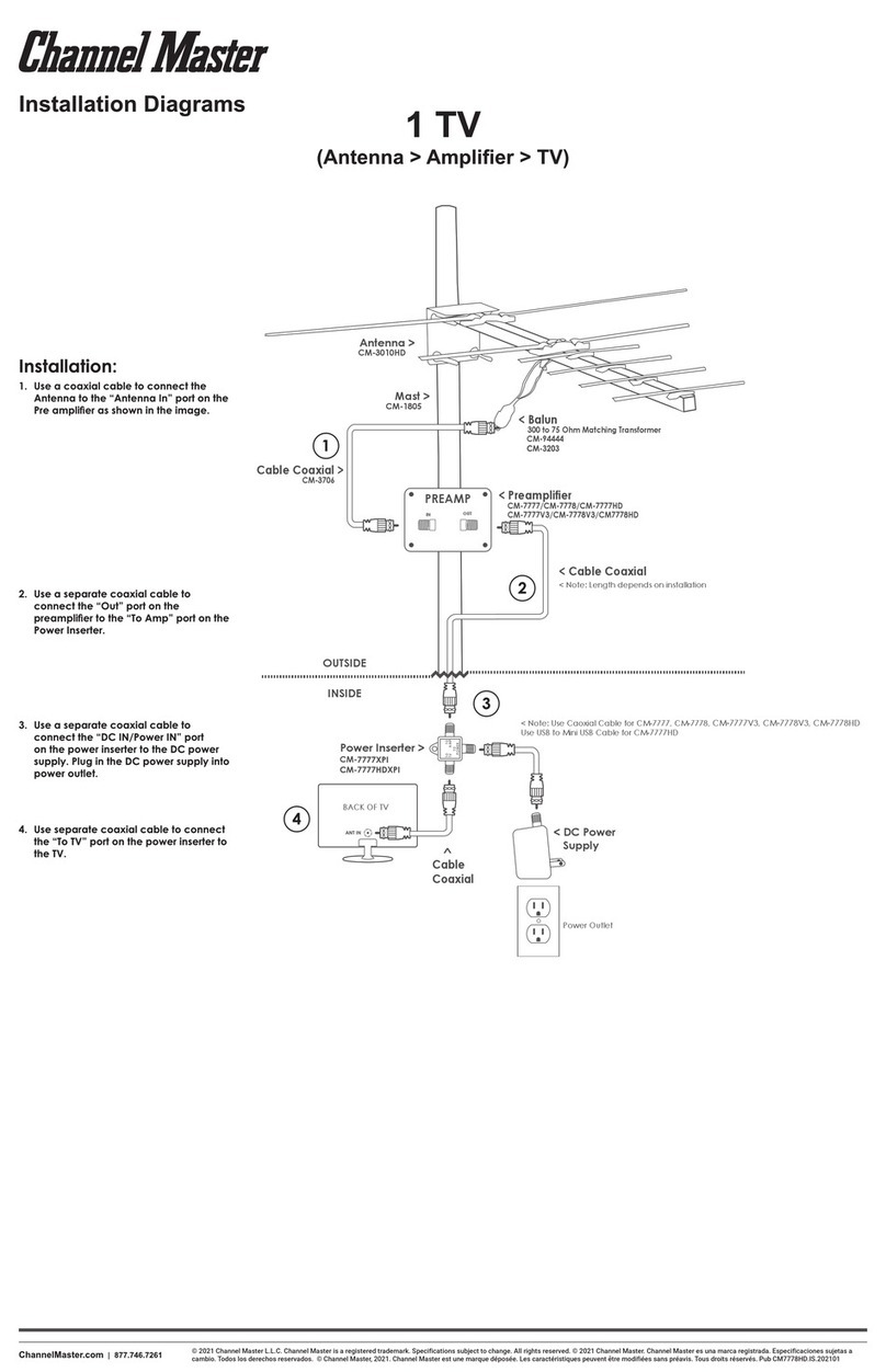
Channel Master
Channel Master 1 TV User manual
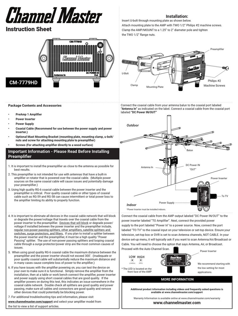
Channel Master
Channel Master CM-7779HD User manual

Channel Master
Channel Master CM-3202 User manual

Channel Master
Channel Master FLATenna User manual
Channel Master
Channel Master 100 User manual
Channel Master
Channel Master Digital ready User manual

Channel Master
Channel Master CM-3000HD User manual

Channel Master
Channel Master Advantage 3016 User manual

Channel Master
Channel Master CM-1776 User manual
