Channel Safety Systems MotionPro Security Lighting Series User manual
CHANNEL SAFETY SYSTEMS t: 0845 884 7000 | w: www.channelsafety.co.uk
INSTRUCTION MANUAL - Issue 1 - 02/2014 | 1
INSTRUCTION MANUAL
CHANNEL SAFETY SYSTEMS t: 0845 884 7000
Peterseld Business Park f: 0845 884 6000
Bedford Road
Peterseld
Hampshire e: sales@channelsafety.co.uk
GU32 3QA w: www.channelsafety.co.uk
Security lighting range
from Channel Safety Systems
™

CHANNEL SAFETY SYSTEMS t: 0845 884 7000 | w: www.channelsafety.co.uk
INSTRUCTION MANUAL - Issue 1 - 02/2014 | 2
INSTRUCTIONS
Each MotionPro Floodlight utilises passive infrared technology to detect heat radiation of moving objects such as people & vehicles.
On activation the lamp will illuminate for a the chosen time period, an integral adjustable daylight sensor ensures night-only operation.
The MotionPro unit comes complete with:-
• Luminaire c/w PIR Sensor unit.
• Instruction manual. Please keep safe for future reference.
• Accessory Pack.
Tools & Parts Needed For Installation
• Suitable drill & bits.
• Terminal or Electricians screwdriver
• Large slotted/Phillips screwdriver
• Wire cutters/strippers
This product has glass front, care must be taken when installing or handling to prevent personal injury or damage to the unit. This light tting must be
installed by a competent person in accordance with the current building & IEE wiring regulations.
Ensure that the electrical supply is correctly isolated by use of the appropriate safe isolation method. This Unit is for outdoor use only and must be mounted
on suitable rigid & strong non-ammable surface. It is not designed to be used as a portable light. This product should be installed using suitably sized and
strong xings.
The surface on which it is to be installed on should be strong enough to support the weight of the light.
This product can be installed on surfaces with normal ammability (wood, plasterboard, masonry). It is not suitable to be installed on, or near highly
ammable surfaces.
Do not install on surfaces which are damp, or electrically conductive. The light should be positioned so that there is at least 500mm between the front of the
tting and any illuminated surface.
This product is designed for permanent connection to a suitably protected xed wiring installation.
Do not carry or lift the oodlight by the mains supply cable.
Only clean the light tting with a soft dry cloth, do not use chemical or abrasive cleaning materials.
The unit can get hot during use. Ensure the unit has cooled before handling. Ensure adequate ventilation space is allowed between the unit and any object
above, in front or to either side of the unit.
Suggested space is 0.5m above, 0.3m to either side & 1.0m in front. This unit should be installed by a qualied electrician.
Selecting The Location
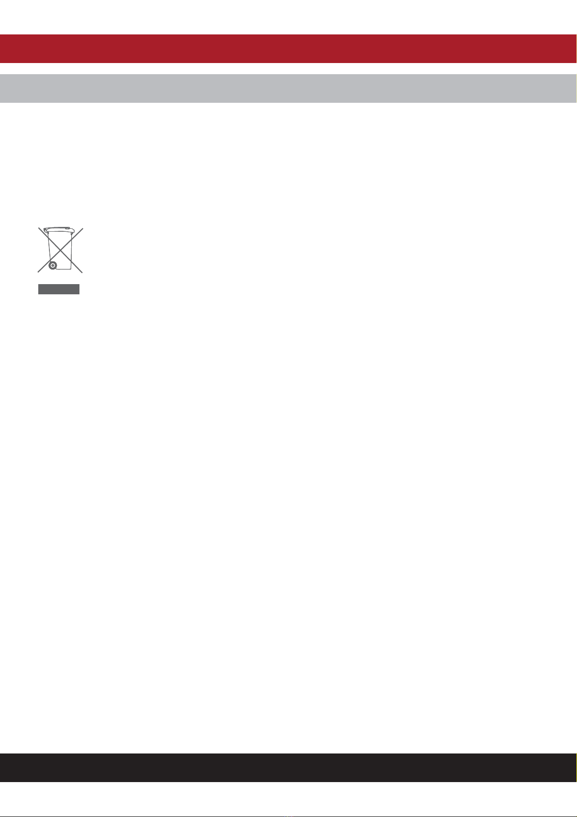
The motion sensor has a number of detection zones, at various vertical and horizontal angles. The maximum range is 12m. The detection angle is 120°
When moving heat source crosses one of these zones it will activate the sensor. Careful positioning of the sensor will be required to ensure optimum per-
formance. The sensor is more sensitive to movement ACROSS its eld of vision than to movement directly TOWARDS. Therefore position the unit so that the
sensor looks ACROSS the likely approach path.
Avoid positioning the sensor where there are any sources of heat in the detection area(extractor fans, tumble dryer exhausts etc.). Reective surfaces (ie pools
of water or white-painted walls) and overhanging branches may cause false activation under extreme conditions.
CHANNEL SAFETY SYSTEMS t: 0845 884 7000 | w: www.channelsafety.co.uk
INSTRUCTION MANUAL - Issue 1 - 02/2014 | 3
INSTALLATION
1. Remove the wiring box cover.
2. The unit is suitable for connection to a 230 V ac 50Hz supply. A 3-core round exible cable of 1.0²mm/1.5²mm gauge is used. A means to isolate the unit
should be installed to switch the power to the unit ON & OFF. This allows the sensor to be easily switched o when not required or for maintenance
purposes.
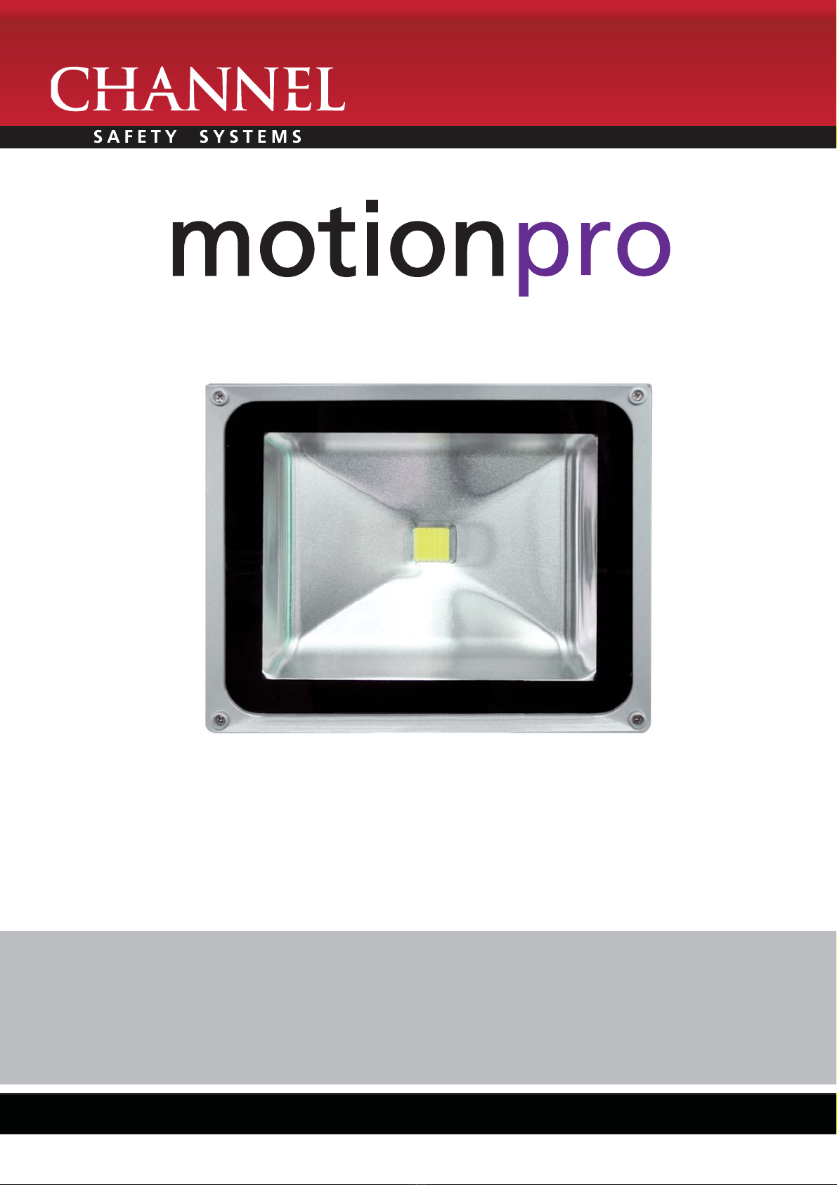
3. Remove the xing bracket from the unit and mark the position of the tting holes using the wall bracket as a template.
4. Drill the holes. Insert the rawl plugs into the holes. Fix the bracket to the wall.
5. Ensure the electrical supply is SWITCHED OFF
6. Connect the cable (SUPPLIED) to the electrical supply. Ensure a suitable junction box is used.
• NEUTRAL (Blue) N
• EARTH (Green/Yellow)
• LIVE (Brown) L
7. Ensure that the connections are secure.
8. Fix the oodlight to the bracket.
Light sensitivity
adjustment
Operation duration
adjustment
PIR SENSOR ADJUSTMENT
To ensure adequate coverage the unit can be set up to allow a walk test to be carried out in normal day light.

CHANNEL SAFETY SYSTEMS t: 0845 884 7000 | w: www.channelsafety.co.uk
INSTRUCTION MANUAL - Issue 1 - 02/2014 | 4
TESTING
Walk Test Procedure
The sensor will rotate from left to right, and tilt forward or backward. Adjust the sensor to point in the required direction.
The unit can be set up in daylight or at night.
Set the time adjustment to minimum (fully clockwise).
Set the daylight sensor to maximum (fully anti clockwise)
Turn the power to the unit on. The lamp will illuminate after approximately 30 seconds. This indicates the unit is correctly installed.
After approximately 5-10 seconds the light will turn o.
The unit is now in Test Mode.
Light sensitivity adjustment
Operation duration adjustment
Test Mode
The lamp will now illuminate for approximately 5 seconds every time movement is detected. Walk around the area you require the unit to cover, each time the
unit is triggered the light will illuminate for the set time. Stand still, or leave the eld of coverage and the light will extinguish.
If the detection area does not meet your requirements, adjust the sensor head accordingly.
Automatic Operation
The unit timer is reset each time it senses movement. Therefore it will only extinguish after the set time once no movement has been detected.
Adjust the time and day light sensor controls to meet your requirement.
On time - Min: 5 second - Max: 6 minutes
Light - Min: 3 lux – Max: 2000 Lux
To set the light level set the control to the mid position, this equate to a‘dusk’level. Check the unit each evening. If the unit is starting to operate too early
(i.e. when it is quite light) adjust the control slightly clockwise. If the unit starts to operate too late (i.e. when it is very dark). Adjust the control slightly
anti -clockwise. Continue to adjust until the unit operates as desired.
CHANNEL SAFETY SYSTEMS t: 0845 884 7000 | w: www.channelsafety.co.uk
INSTRUCTION MANUAL - Issue 1 - 02/2014 | 5
LAMP REPLACEMENT
This luminaire uses a sealed LED lamp and is maintenance free. No lamp replacement is required.
Disposal
At the end of the working life of the light or if you wish to upgrade or replace the unit it is essential that the correct disposal method is used. Please check with
your supplier or local authority for the options available.
Channel Safety Systems Limited are registered under the‘WEEE Directive’(Waste from Electrical and Electronic Equipment), our registration number is WEE/
JK0060TU
Assistance
If you require assistance or the light becomes defective, please return it to where you purchased it. Alternatively you can call our helpline for advice. Please
note the Helpline can only give product advice, not site specic advice.

CHANNEL SAFETY SYSTEMS t: 0845 884 7000 | w: www.channelsafety.co.uk
INSTRUCTION MANUAL - Issue 1 - 02/2014 | 6
PASSIVE INFRARED MOTION DETECTOR
The MP/PIR/BK PIR detector is used to automatically control lighting equipment. It detects heat movement within a given ‘eld of view’.
It has a wide eld of view which can be adjusted in both the vertical and the horizontal planes. The detector incorporates an built in adjustable daylight
sensor and adjustable timer.
SPECIFICATION
Power Source 220-240V/AC
Detection Range 140
Power Frequency 50Hz
Working Temperature -20 ~ +40C
Ambient Light 3-2000 Lux (Adjustable)
Working Humidity <93%RH
Time Delay Min: 10 sec ± 3 sec
Max: 7 min ± 2 min
Installation Height 1.8m~2.5m
Power Consumption 0.45W
Rated Load 1200W (incandescent lamp)
300W (energy-saving lamp)
Detection of movement 0.6~1.5m/s
Detection range 12m max (<24oC)
IP Rating IP44
CHANNEL SAFETY SYSTEMS t: 0845 884 7000 | w: www.channelsafety.co.uk
INSTRUCTION MANUAL - Issue 1 - 02/2014 | 7
OPERATION
The MP/PIR/BK PIR detector can be adjusted to operate at variable light levels, from full daylight to less than 3 LUX.
The MP/PIR/BK PIR detector has a variable timer which is adjustable from10 second to 7 minutes. Each time the detector is triggered the timer
resets and starts the time period again. This ensures that the light is on no matter how long a moving person or vehicle is in the eld of view.
Best sensitivity is across the eld of view, objects which move towards the detector will be detected less quickly.

CHANNEL SAFETY SYSTEMS t: 0845 884 7000 | w: www.channelsafety.co.uk
INSTRUCTION MANUAL - Issue 1 - 02/2014 | 8
Installation should be carried out by a qualied electrician.
• Ensure the power is o and correctly isolated.
• Remove the screw from the bottom of the unit (a)
• Choose the cable entry points, rear or bottom entry.
• Fix the base to a suitable surface at the required location.
• Connect the power & load.
• Fix PIR back on to the base
PASSIVE INFRARED MOTION DETECTOR INSTALLATION

CHANNEL SAFETY SYSTEMS t: 0845 884 7000 | w: www.channelsafety.co.uk
INSTRUCTION MANUAL - Issue 1 - 02/2014 | 9
ADJUSTMENT AND TESTING
• Turn the timer switch clockwise to the minimum setting (about 10 seconds).
• Turn the lux level switch clockwise to the maximum light level (sun symbol).
• Apply power. The unit takes about 30 seconds to ‘warm up’. The LED indicator and the load light(s) will operate.
• After this period the LED indicator & load light(s) will extinguish
• If there is no movement in the eld of view the light will not illuminate until the PIR is triggered.
• To test the ‘eld of view’area, walk out of range and then walk across the‘eld of view’. Once the unit is triggered the light will illuminate for
approximately 10 seconds (once movement has stopped). Adjust the detection head as required for best coverage.
• Once the unit is adjusted for coverage adjust the time setting by turning the time switch anti-clockwise. To accurately adjust the timer, simply trigger the
unit and time the‘light on’time. Adjust according to your requirements.
• To adjust the lux (light level) at which the unit will operate, turn the lux switch anti-clockwise to the mid point. Wait until the required level of darkness
and attempt to trigger the unit. If it fails to operate, adjust accordingly. The minimum setting is 3 lux which is almost total darkness. Be aware of other
light sources such as street lighting which may aect the ambient lighting levels.
Please note:
• Avoid installing the PIR detector near sources of heat or cold air such as air conditioning units, boilers, ues etc.
• Ensure clear‘eld of view’.
• Ensure the PIR coverage is not aected by moving objects such as parked vehicles, doors, shutters, trees etc.

INSTRUCTION MANUAL
CHANNEL SAFETY SYSTEMS t: 0845 884 7000
Peterseld Business Park f: 0845 884 6000
Bedford Road
Peterseld
Hampshire e: sales@channelsafety.co.uk
GU32 3QA w: www.channelsafety.co.uk
Table of contents
Popular Floodlight manuals by other brands


Ledvance
Ledvance 100W/830 3Y installation manual

Eterna
Eterna FL124B installation instructions

Maurer
Maurer 82081 user manual

Ibiza
Ibiza LEDFLOOD-10WH-MD user manual

hylite
hylite MIGHTYLITE PRO MLP120 Installation & operating instructions

Larson Electronics
Larson Electronics HAL-PRM-150W-LED instruction manual

GTV
GTV LD-ILUXC10W-64 user manual

thomann
thomann STAIRVILLE LED Bar 120/4 RGB DMX user manual

American DJ
American DJ Micro Galaxian User instructions

Bunker Hill Security
Bunker Hill Security LED-SOLAR Owner's manual & safety instructions

ADJ
ADJ X-COLOR LED PLUS User instructions

Ferm
Ferm FLM1002 Original instructions