Part No. HS-2
2-WAY SPLITTER/COMBINER
5MHz-1GHz All Port DC passing
TM
CHANN EL VI S I O N
IN/out
OUT/in OUT/in
Part No. HS-2
2-WAY SPLITTER/COMBINER
5MHz-1GHz All Port DC passing
TM
CHANN EL VI S I O N
IN/out
OUT/in OUT/in
TV OutputsTV Outputs
CATV InCATV In
PowerPower
+15VDC+15VDC EmittersEmitters
IRIR
1122334455667788
TV Output Status: Green = CATV, Red = ModulatorTV Output Status: Green = CATV, Red = Modulator
1122334455667788
AABB
Mod InMod In
PRO
CH AN NE L
TM
VI S I O N
CH AN NE L
VI S I O NTM
Model
P-0328
3X8 Digital Cable Combiner
Pat. Pending
PwrPwr
IRIR
Part No. HS-2
2-WAY SPLITTER/COMBINER
5MHz-1GHz All Port DC passing
TM
CHA NNE L VIS IO N
IN/out
OUT/inOUT/in
Part No. HS-2
2-WAY SPLITTER/COMBINER
5MHz-1GHz All Port DC passing
TM
CHA NNE L VIS IO N
IN/out
OUT/inOUT/in
Input from
CATV
To Mod In on another P-0328
For system expansion:
To CATV In on another P-0328
RF OUTRF OUT
DC 15V INDC 15V IN
OUTPUT
IR
OUTPUT
IR
CABLECABLE
ANTENNAANTENNA
ANTENNA + CABLEANTENNA + CABLE
VIDEOVIDEO
AUDIOAUDIO
L RL R
BB
AA
VIDEOVIDEO
AUDIOAUDIO
L RL R
DD
CC
1144
33
22
11223344
OUTPUT
IR
OUTPUT
IR
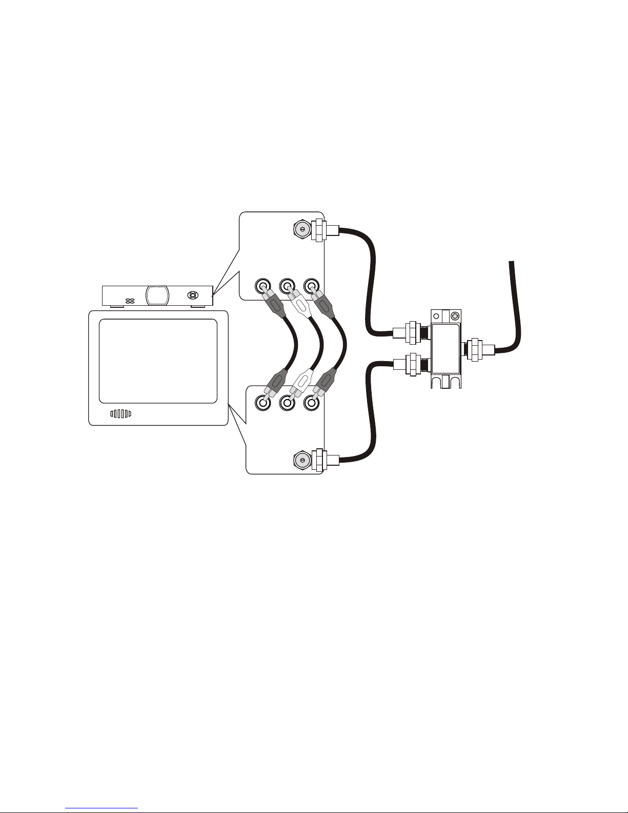
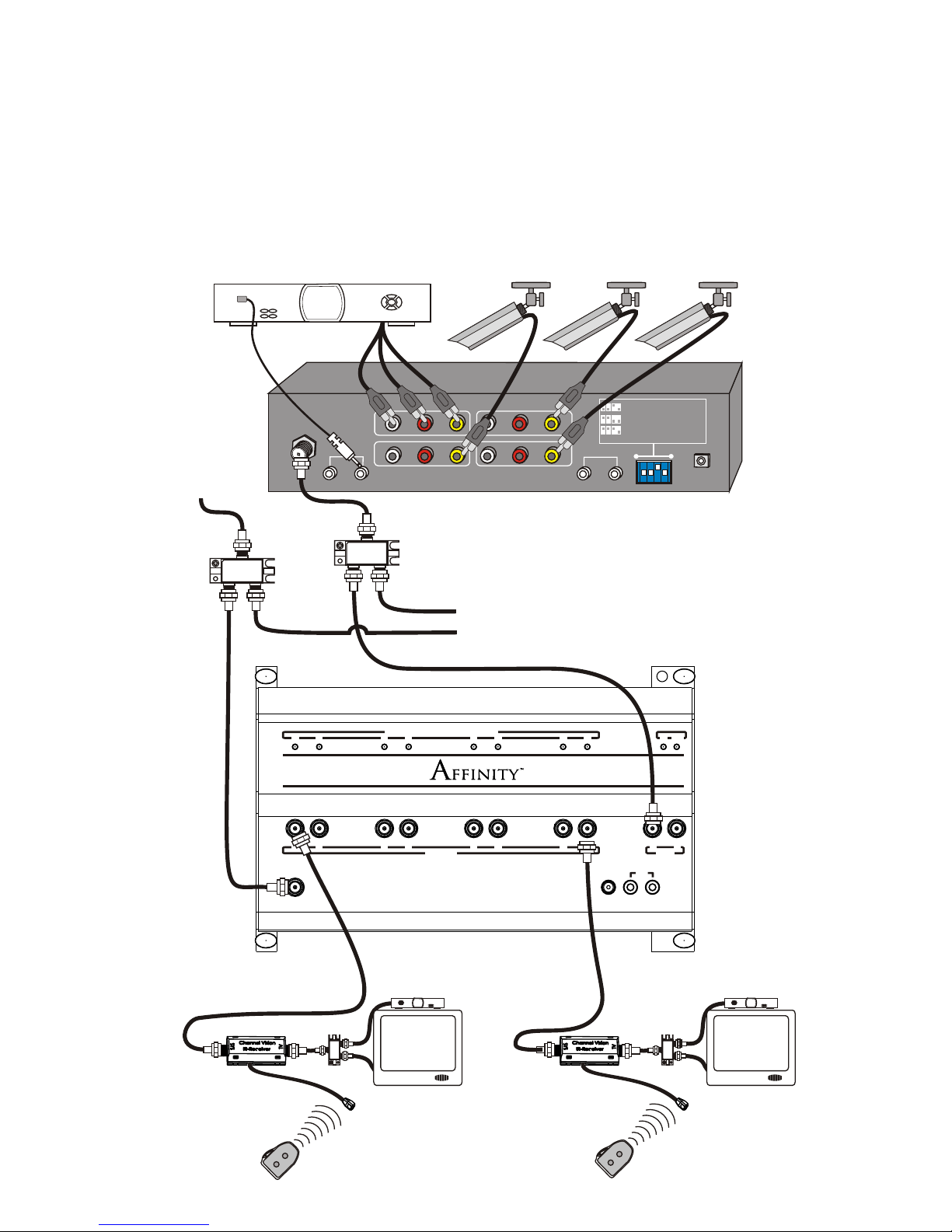
Sat Receiver
Camera
CameraCamera
P-0328
6
Expanding the System
The P-0328 comes with one IR coax adaptor which will allow viewing of both
CATV and Mod at one TV location. To view both signals at more TVs,
additional IR coax adaptors can be purchased; compatible models are: IR-
4101 or IR-4100 used with an IR-2400. If no IR coax adaptor is used, only
CATV signals will be viewable. To create systems with more than 8 locations,
simply split the output of the modulator and the CATV feed, then connect the
outputs of the splitters to each P-0328.
Room 1 Room 8
An IR coax adapter can
be used on all 8 outputs.
Rooms without IR coax
adaptors will only see CATV.
ulaModtor
CATV
l
Channe
Vsi ionTM
5A011
Modulator
C TA V
Chan l
ne
VisionTM
051A 1
TV OutputsTV Outputs
CATV InCATV In
PowerPower
+15VDC+15VDC EmittersEmitters
IRIR
1122334455667788
TV Output Status: Green = CATV, Red = ModulatorTV Output Status: Green = CATV, Red = Modulator
1122334455667788
AABB
Mod InMod In
PRO
CH AN NE L
TM
VI S I O N
CH AN NE L
VI S I O NTM
Model
P-0328
3X8 Digital Cable Combiner
Pat. Pending
PwrPwr
IRIR
7
Troubleshooting
If your IR system is not working, check to see if the P-0328 is feeding
approximately 12 Volts DC onto the coax between the shield and center
pin. (Any voltage between 8-12VDC is OK). If there is no voltage
between the center pin and shield, check the connectors on each end of
the coax to make sure there are no shorts (no shielding touching the
center conductor).
If you are using an RF splitter between the modulator and the P-0328 or
between the P-0328 and the IR coax adaptor (IR-4101), check to make sure
you have approximately 8-12 Volts DC on the coax going into the IR-4101.
If there is no voltage at that point, check the following items:
1. If you are using a splitter on the TV outputs of the P-0328, make sure it is
DC passing. Traditional splitters will short out DC voltage traveling on the
coax and prevent your IR system from working.
2. If you are using a splitter on the TV outputs of the P-0328, make sure that
there are DC blocks (model 3109) on any output from the RF splitter that
will not be connected to an IR-4101. If outputs from the splitter are
connected directly to TV sets without going through an IR-4101 or DC
block, the system voltage will be shorted out by the input of the TV set.
3. Double check the fittings at the end of your coax cables. If a little bit of
shielding is touching the center pin, the voltage will be shorted out and
the system will not work.
4. Don’t worry. There are 8 IR engines in the P-0328 one for each TV
output. The IR engines have a current limiting circuit. If an engine is
shorted (due to a bad connection or a non-DC passing splitter) nothing
will be harmed.
VDC