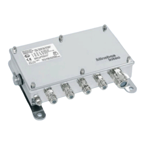
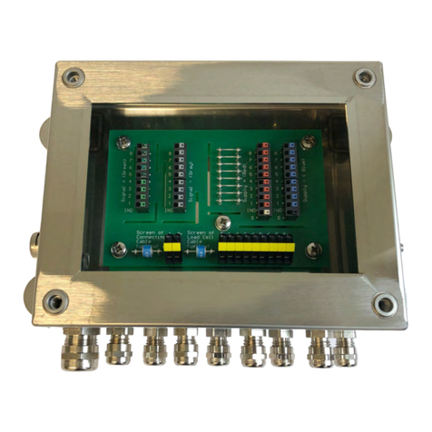
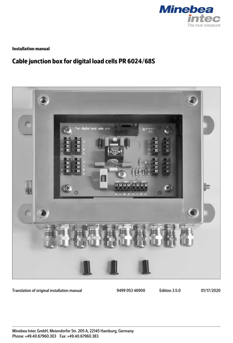
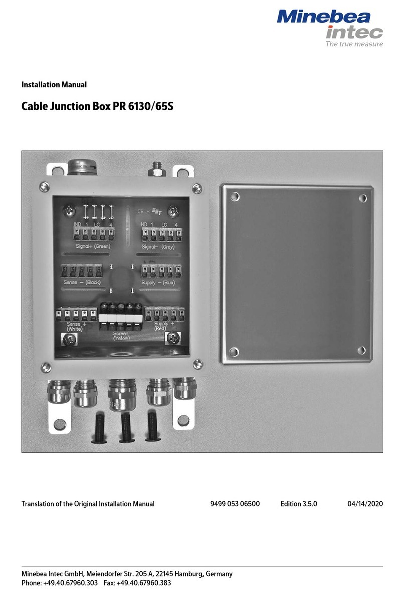
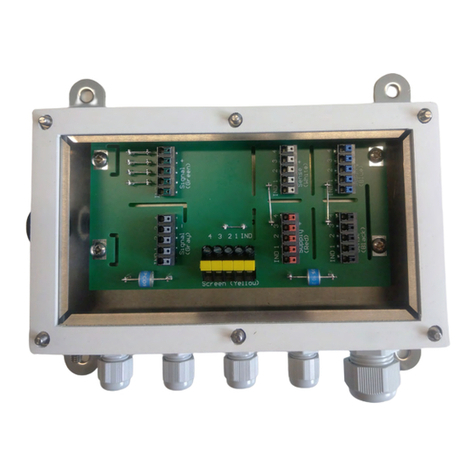
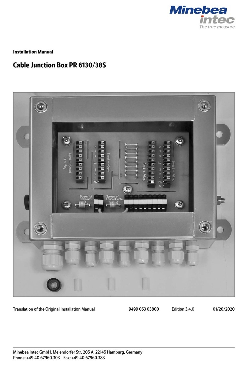
Minebea Intec IE11357 User manual

Operating Instructions | Betriebsanleitung | Mode d’emploi
Instrucciones de funcionamiento | Istruzioni per l’installazione
Relay Box IE11357
Relaisbox IE11357
Boîtier relais IE11357
Caja de relé IE11357
Scatola relè IE11357
98647-003-98

2 Relay Box IE11357 Relay Box IE11357 3
English - page 3
Deutsch - Seite 11
Français – page 19
Español – página 27
Italiano - pagina 35

Relay Box IE11357 3
Contents Warnings and Safety
Precautions
3 Contents
3 Warnings and Safety Precautions
4 Intended Use
5 Installation
6 Wiring Diagram
8 Cabling Diagram for YCC02-
RELAIS01 Accessory Cable
9 Cabling Diagram for YCC02-
RELAIS02 Accessory Cable
10 Specifications
– Do not use this equipment in hazardous
areas.
– Disconnect the IE11357 relay box from
power before opening the housing.
– When using an external power sup-
ply, the surge capacity in accordance
with EN 61326 must be ensured by the
power source.
–If the IE11357 is con-
nected to a power source
that is not safely electri-
cally isolated from the
mains supply (line power)
(IEC 364-4-41), a warning
label indicating hazardous
voltage must be affixed to
the IE11357 in a highly
visible location.
– Non-permissible operating status:
If the IE11357 relay box is connected
to a power supply and the control
device (scale or indicator) is not, this
may result in an undefined relay status.
For this reason, it is essential to make
sure both the relay box and the control
device are connected to power.
Note on this Manual
Before installing and using the IE11357
relay box, make sure to read the
manufacturer’s instructions provided
with the digital input/output module
(NuDAM).

4 Relay Box IE11357 Relay Box IE11357 5
Intended Use
The IE11357 relay box is designed for
connecting peripheral devices with
higher output levels to a Minebea Intec
control device, such as the Combics 3
(e.g., with the “Filling with Extras” ap-
plication, Option H4).
Connect the IE11357 relay box to the
RS-485 interface using one of the fol-
lowing connecting cables:
– YCC02-RELAIS01 for connection to
Combics 3
– YCC02-RELAIS02 for connection to
Combics 3
The relay outputs are wired directly to
the control elements (to be connected
by the customer).
The power supply to the IE11357 relay
box is to be provided by the custom-
er.
Peripheral device (e.g., filling system)
Relay outputs Inputs
Control device (Combics)
Power supply
provided by
customer
(+10 V to
+30 V DC)
RS-485
Relay card Digital input/
output module
(NuDAM)

Relay Box IE11357 5
Installation
§ Disconnect equipment from power
before opening the relay box.
§ To open the relay box, remove the
sechs screws from the cover plate.
§ Installing the cable gland and cable:
– Prepare the cable opening by breaking
out the pre-punched M20 disk.
– Guide the enclosed cable gland
(M20 x 1.5) into the opening and
secure it inside the housing with the
counternut (1).
– Route the cable (2) through the cable
gland. Tighten the screw-down nut
(3) until the sealing clamp (4) forms a
slight ridge.
§ Mount the cable on the relay card in
accordance with the relevant wiring
diagram.
12
3
4

6 Relay Box IE11357 Relay Box IE11357 7
Wiring Diagram
Wiring Diagram
6
6
20
11
1
10
DI6
DI5
DI4
DI3
DI2
DI1
DI0
DO0
DO1
DO2
DO7
DO6
DO5
DO4
DO3
DEFAULT*
(Y)DATA+
(G)DATA-
(R)+Vs
(B)GND
Relay 8 Input 7
Input 6
Relay 7 Input 5
Relay 6 Input 4
Relay 5 Input 3
Relay 4 Input 2
Input 1
Controller Relay 1
Controller Relay 2
Relay 3
Wiring on the Digital Input/Output Module (I/O Modul)
PIN Designation Wiring Function Assignment in
control device
1 DO 7 Internally connected *) Switches relay 8 Output 8
2 DO 6 Internally connected *) Switches relay 7 Output 7
3 DO 5 Internally connected *) Switches relay 6 Output 6
4 DO 4 Internally connected *) Switches relay 5 Output 5
5 DO 3 Internally connected *) Switches relay 4 Output 4
6 DEFAULT* Remains open
7 (Y)DATA+ Control device; RS-485+ (TxD-RxD+)
8 (G)DATA- Control device; RS-485– (TxD-RxD–)
9 (R)+ VS Internally connected *)
10 (B)GND Internally connected *)
11 DO 2 Internally connected *) Switches relay 3 Output 3
12 DO 1 Internally connected *) Switches relay 2 Output 2
13 DO 0 Internally connected *) Switches relay 1 Output 1
14 DI 0 Digital input Input 1
15 DI 1 Digital input Input 2
16 DI 2 Digital input Input 3
17 DI 3 Digital input Input 4
18 DI 4 Digital input Input 5
19 DI 5 Digital input Input 6
20 DI 6 Digital input Input 7
*) Factory connection to relay card

Relay Box IE11357 7
Wiring on the Relay Card
Supply voltage 2
provided by customer (+10 V to +30 V DC)
Ground 3 (provided by customer)
7
123456
110
20 11
87 3
54
6
21
Relay 1
Relay 2
Relay 3
Relay 4
Relay 5
Relay 6
Relay 7
Relay 8

8 Relay Box IE11357 Relay Box IE11357 9
Cabling Diagram
for YCC02-RELAIS01 Accessory Cable
Connection between the VF3033 and the COM2 interface on the Combics 3 (CISL3):
VF3033
(B) GND + (10) §
———–——–––––––––––———–———GND (7)
(Y) Data + (7) §
———–———— RS485+ —–———RS485+ (3)
(G) Data – (8) §
———–———— RS485– —–———RS485– (5)
––––––––––§–(1)
Connection between VF3033 and the Unicom interface on the Combics 3 (CISL3):
VF3033
(B) GND + (10) §
———–——–––––––––––———–———GND (8)
(Y) Data + (7) §
———–———— RS485+ —–———RS485+ (16)
(G) Data – (8) §
———–———— RS485– —–———RS485– (9)
––––––––––§–(1)
Isolate unused cable ends in accordance with industry standards.
8

Relay Box IE11357 9
Cabling Diagram
for YCC02-RELAIS02 Cable (Accessory)
YSB02 YCC02-RELAIS02
Designation Pin Cable Label
(Y) DATA+ 7
(B) GND 10
(G) DATA– 8
Connection among the YSB02, VF3033 and the COM2 interface on the Combics 3 (CIS3):
YSB02/VF3033
(Y) Data + (7) §
———–———— RS485+ —–———RS485+ LV2 (10)
(G) Data – (8) §
———–———— RS485– —–———RS485– LV2 (5)
(B) GND + (10) §
———–—————––––––––––––———GND LV2 (2)
§
=
Connection among the YSB02, VF3033 and the UniCom interface on the Combics 3 (CIS3):
YSB02/VF3033
(Y) Data + (7) §
———–———— RS485+ —–———RS485+ LV4 (3)
(G) Data – (8) §
———–———— RS485– —–———RS485– LV4 (4)
(B) GND + (10) §
———–—————––––––––––––———GND LV2 (2)
§
=
Connect the cable in accordance with the pin assignments specified for the Combics
indicator (CIS3). Isolate unused cable ends in accordance with industry standards.
9
§
———–———— RS485 ———–———— RS485+ ———–————§
§
———–———— +GND ———–———— G N D ———–————§
§
———–———— RS485- ———–———— RS485- ———–————§
§
———–———— MINOR ———–———— MINOR ———–————§
§
———–———— PARES ———–———— PARES ———–————§
§
———–———— MAJOR ———–———— MAJOR ———–————§
§
———–———— S E T ———–———— S E T ———–————§
§
———–———— UNI_IN ———–———— UNI_IN ———–————§
§
———–———— C O M ———–———— C O M ———–————§
§
———–———— L I N E ———–———— L I N E ———–————§
§

10 Relay Box IE11357 Relay Box IE11357 11
Specifications
Relay Card
Relay output unit 1 N/O (1 contact closer)
– Maximum charge: 250 V AC/3 A; 30 V DC/3 A
– Max. hysteresis 1 million
Power supply:
– Supply voltage: +10 V DC to +30 V DC
– Power consumption: 3.0 W maximum
Digital Input/Output Module
Digital inputs:
– Number: 7
– Low level: 0 to +0.7 V
– High level: +3.5 to +30 V
– Internal pull-up resistor: 10 kohms
– Max. power consumption: 0.5 mA
– Inputs switched through application of corresponding voltage or through
switching the input against GND
Supply voltage: +10 V DC to +30 V DC
Current consumption: 30 mA
Power consumption: 400 mW
IE11357 relay box
Allowable storage temperature: -25°C to +80°C (-13°F to +176°F)
Operating temperature range: -10°C to +70°C (+14°F to +158°F)
Housing: Fiberglass reinforced polycarbonate housing (IP66)
Cable glands: M20 x 1.5

Relay Box IE11357 11
Inhalt
11 Inhalt
11 Warn- und Sicherheitshinweis
12 Verwendungszweck
13 Installation
14 Verdrahtungsplan
16 Verbindungsplan für Zubehörkabel
YCC02-RELAIS01
17 Verbindungsplan für Zubehörkabel
YCC02-RELAIS02
18 Technische Daten
Warn- und
Sicherheitshinweis
– Gerät nicht in explplosionsgefärdeten
Bereichen einsetzen.
– Vor dem öffnen der Relaisbox IE11357
Netzspannung trennen.
– Für die externen Spannungsversorgung
muss eine Stoßspannungsfestigkeit ge-
mäß EN61326 durch die Versorgungs-
quelle gewährleistet sein.
–Beim Anschluss der
Relaisbox IE11357 an
Spannungen die nicht
sicher vom Netz getrennt
sind (IEC 364-4-41),
muss ein Haftetikett, das auf gefährli-
che Spannungen hinweist, gut sichtbar
an der Relaisbox IE11357 angebracht
werden.
– Verbotener Betriebszustand:
Wird die Relaisbox IE11357 mit Span-
nung versorgt, und das Steuergerät
(Waage, Auswertegerät) nicht, können
hieraus undefinierte Zustände an den
Relais entstehen. Es ist daher stets
darauf zu achten, dass sowohl das
Relaismodul aus auch das Steuergerät
versorgt sind.
Hinweis
Für die Verwendung und Inbetrieb-
nahme der Relaisbox IE11357 ist auch
die dem digitalen Ein-/Ausgabemoduls
(Nudam) beiliegende Betriebsanleitung
des Herstellers zu beachten.

12 Relay Box IE11357 Relay Box IE11357 13
Verwendungszweck
Die Relaisbox IE11357 dient dem An-
schluß von Peripheriegeräten mit grö-
ßeren Leistungen an ein Minebea Intec
Steuergerät z.B. Combics 3 Dosieren
Plus (Option H4).
Die Relaisbox IE11357 wird an die
RS485 Schnittstelle angeschlossen.
Anschlusskabel:
– YCC02-RELAIS01 zum Anschluss an
Combics 3.
– YCC02-RELAIS02 zum Anschluss an
Combics 3.
Die Relais-Ausgänge werden direkt mit
den Steuerelementen verdrahtet (Ver-
bindung erfolgt kundenseitig).
Die Stromversorgung der Relaisbox
IE11357 erfolgt kundenseitig.
Peripheriegerät (z.B. Dosieranlage)
Relaisausgänge Eingänge
Steuergerät (Combics)
Stromver-
sorgung
kundenseitig
(+10 V bis
+30 V DC)
RS485
Relaiskarte digitales Ein-
Ausgabemodul
(Nudam)

Relay Box IE11357 13
Installation
§ Vor dem öffnen der Relaisbox IE11357
Netzspannung trennen
§ Zum Öffnen die sechs Schrauben am
Deckel lösen. Deckel abnehmen.
§ Kabelverschraubung und Kabel montie-
ren:
– Vorprägung M20 am Gehäuse ausbre-
chen.
– Beiliegende Kabelverschraubung
M20 x 1,5 durch Ausbruch stecken
und mit Gegenmutter (1) von innen
sichern.
– Kabel (2) durch die Kabelverschrau-
bung stecken. Druckmutter (3) anzie-
hen bis der Dichteinsatz (4) zwischen
Druckmutter und Kabel einen kleinen
Wulst bildet.
§ Kabel entsprechend der Verdrahtungs-
pläne an der Relaiskarte montieren.
12
3
4

14 Relay Box IE11357 Relay Box IE11357 15
Verdrahtungsplan
Relais 8 Eingang 7
Eingang 6
Relais 7 Eingang 5
Relais 6 Eingang 4
Relais 5 Eingang 3
Relais 4 Eingang 2
Eingang 1
Steuergerät Relais 1
Steuergerät Relais 2
Relais 3
Verdrahtung am digitalen Ein-/Ausgabemodul (Nudam)
PIN Bezeichnung Verdrahtung Funktion Zuweisung
im Steuergerät
1 DO 7 intern belegt *) schaltet Relais 8 Ausgang 8
2 DO 6 intern belegt *) schaltet Relais 7 Ausgang 7
3 DO 5 intern belegt *) schaltet Relais 6 Ausgang 6
4 DO 4 intern belegt *) schaltet Relais 5 Ausgang 5
5 DO 3 intern belegt *) schaltet Relais 4 Ausgang 4
6 DEFAULT* bleibt offen
7 (Y)DATA+ Steuergerät; RS485+ (TxD-RxD+)
8 (G)DATA- Steuergerät; RS485- (TxD-RxD-)
9 (R)+VS intern belegt *)
10 (B)GND intern belegt *)
11 DO 2 intern belegt *) schaltet Relais 3 Ausgang 3
12 DO 1 intern belegt *) schaltet Relais 2 Ausgang 2
13 DO 0 intern belegt *) schaltet Relais 1 Ausgang 1
14 DI 0 Digital input Eingang 1
15 DI 1 Digital input Eingang 2
16 DI 2 Digital input Eingang 3
17 DI 3 Digital input Eingang 4
18 DI 4 Digital input Eingang 5
19 DI 5 Digital input Eingang 6
20 DI 6 Digital input Eingang 7
*) Ab Werk Verbindung zur Relaiskarte
14
20
11
1
10
DI6
DI5
DI4
DI3
DI2
DI1
DI0
DO0
DO1
DO2
DO7
DO6
DO5
DO4
DO3
DEFAULT*
(Y)DATA+
(G)DATA-
(R)+Vs
(B)GND

Relay Box IE11357 15
Verdrahtung an Relaiskarte
Versorgungsspannung 2
kundenseitig
(+10 V bis +30 V DC)
Ground 3
(kundenseitig)
15
123456
110
20 11
87 3
54
6
21
Relais 1
Relais 2
Relais 3
Relais 4
Relais 5
Relais 6
Relais 7
Relais 8

Verbindungsplan für Zubehörkabel
YCC02-RELAIS01
Verbindung zwischen VF3033 und COM2 Schnittstelle von Combics 3 (CISL3):
VF3033
(B) GND + (10) §
———–——–––––––––––———–———GND (7)
(Y) Data + (7) §
———–———— RS485+ —–———RS485+ (3)
(G) Data – (8) §
———–———— RS485– —–———RS485– (5)
––––––––––§–(1)
Verbindung zwischen VF3033 und Unicom Schnittstelle von Combics 3 (CISL3):
VF3033
(B) GND + (10) §
———–——–––––––––––———–———GND (8)
(Y) Data + (7) §
———–———— RS485+ —–———RS485+ (16)
(G) Data – (8) §
———–———— RS485– —–———RS485– (9)
––––––––––§–(1)
Nicht belegte Kabelenden sind fachgerecht zu isolieren.
16
16 Relay Box IE11357 Relay Box IE11357 17

Relay Box IE11357 17
Verbindungsplan für Zubehörkabel
YCC02-RELAIS02
YSB02 YCC02-RELAIS02
Bezeichnung PIN Kabel- Label
enden
(Y) DATA+ 7
(B) GND 10
(G) DATA– 8
Verbindung zwischen YSB02, VF3033 und COM2 Schnittstelle von Combics 3 (CIS3):
YSB02/VF3033
(Y) Data + (7) §
———–———— RS485+ —–———RS485+ LV2 (10)
(G) Data – (8) §
———–———— RS485– —–———RS485– LV2 (5)
(B) GND + (10) §
———–—————––––––––––––———GND LV2 (2)
§
=
Verbindung zwischen YSB02, VF3033 und UniCom Schnittstelle von Combics 3 (CIS3):
YSB02/VF3033
(Y) Data + (7) §
———–———— RS485+ —–———RS485+ LV4 (3)
(G) Data – (8) §
———–———— RS485– —–———RS485– LV4 (4)
(B) GND + (10) §
———–—————––––––––––––———GND LV2 (2)
§
=
Die Kabel sind entsprechend der Belegungspläne des Combics-Auswertegerätes (CIS3)
aufzulegen. Nicht verwendete Kabelenden sind fachgerecht zu isolieren.
17
§
———–———— RS485 ———–———— RS485+ ———–————§
§
———–———— +GND ———–———— G N D ———–————§
§
———–———— RS485- ———–———— RS485- ———–————§
§
———–———— MINOR ———–———— MINOR ———–————§
§
———–———— PARES ———–———— PARES ———–————§
§
———–———— MAJOR ———–———— MAJOR ———–————§
§
———–———— S E T ———–———— S E T ———–————§
§
———–———— UNI_IN ———–———— UNI_IN ———–————§
§
———–———— C O M ———–———— C O M ———–————§
§
———–———— L I N E ———–———— L I N E ———–————§
§

18 Relay Box IE11357 Relay Box IE11357 19
Technische Daten
Relaiskarte
Relais-OUT 1 N/O (1 Schließer)
– Maximale Belastung: 250VAC/3A; 30VDC/3A
– max. Schaltspiele 1 Mio
Stromversorgung:
– Versorgunsspannung: +10 V DC bis +30 V DC
– Leistungsaufnahme: 3,0 W maximal
Digitales Ein-/Ausgabemodul
Digitale Eingänge:
– Anzahl: 7
– Low-Pegel: 0 V bis +0,7 V
– High-Pegel: +3,5 V bis +30V
– interner Pull-up Widerstand: 10 kOhm
– Max Stromaufnahme: 0,5 mA
– Schalten der Eingänge durch Anlegen der entsprechenden Spannung oder durch
Schalten des Eingangs gegen GND
Versorgunsspannung: +10 V DC bis +30 V DC
Stromaufnahme: 30 mA
Leistungsaufnahme: 400 mW
Relaisbox IE11357
Lagertemperatur: -25° C bis +80° C
Einsatztemperatur: -10° C bis +70° C
Gehäuse: Glasfaserverstärktes Polycarbonat-Gehäuse (IP66)
Kabeldurchführungen: M20 x 1,5

Relay Box IE11357 19
Sommaire
19 Sommaire
19 Conseils de sécurité
20 Description générale
21 Installation
22 Schéma de connexion
24 Schéma de câblage pour le câble
accessoire YCC02-RELAIS01
25 Schéma de câblage pour le câble
accessoire YCC02-RELAIS02
26 Caractéristiques techniques
Conseils de sécurité
– Ne pas utiliser l’appareil dans des
domaines à risques d’explosions.
– Avant d’ouvrir le boîtier relais IE11357,
le débrancher de l’alimentation en
courant.
– Pour alimenter le boîtier relais par
une source d’alimentation électrique
externe, la résistance aux ondes de
surtension conformément à EN61326
doit être assurée par la source d’alimen-
tation.
– Lors du raccordement du
boîtier relais IE11357
à des tensions qui ne sont
pas séparées du réseau de
manière sûre
(IEC 364-4-41),
une étiquette adhésive qui indique des
tensions dangereuses doit être apposée
sur le boîtier relais de manière à être
parfaitement visible.
– Etat de fonctionnement interdit :
Si le boîtier relais IE11357 est alimenté
en courant et que l’appareil de com-
mande (balance, indicateur) ne l’est pas,
il peut en résulter des états non définis
sur le relais. Il faut donc constamment
veiller à ce que le module relais ainsi
que l’appareil de commande soient
alimentés en courant.
Remarque
Pour utiliser et mettre en service le boî-
tier relais IE11357, il faut également se
reporter au mode d’emploi du fabricant
joint au module d’entrée/sortie numé-
rique (Nudam).

20 Relay Box IE11357 Relay Box IE11357 21
Description générale
Le boîtier relais IE11357 sert à rac-
corder des appareils périphériques de
très grandes puissances à un appareil
de commande Minebea Intec par ex.
Combics 3 Dosage Extra (option H4).
Le boîtier relais IE11357 doit être rac-
cordé à l’interface RS485.
Câbles de raccordement :
– YCC02-RELAIS01 pour le raccordement
à Combics 3.
– YCC02-RELAIS02 pour le raccordement
à Combics 3.
Les sorties relais sont directement
connectées aux éléments de commande
(connexion effectuée par le client).
L’alimentation électrique du boîtier
relais IE11357 est effectuée par le
client.
Appareil périphérique (par ex. dispositif de dosage)
Sorties relais Entrées
Appareil de commande
Alimentation
en courant
du client
(+10 V à
+30 V DC)
RS485
Carte relais Module d’entrée/
sortie numérique
Table of contents
Other Minebea Intec Cable Box manuals

Minebea Intec
Minebea Intec PR 6130/64Sa User manual
Minebea Intec
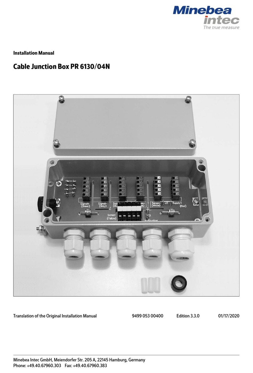
Minebea Intec Cable Junction Box PR 6130/35S User manual

Minebea Intec
Minebea Intec PR 6130/38S User manual

Minebea Intec
Minebea Intec Weighbridge PR 6021/18 User manual

Minebea Intec
Minebea Intec PR 6130/64Sa User manual

Minebea Intec
Minebea Intec PR 6130/68S User manual

Minebea Intec
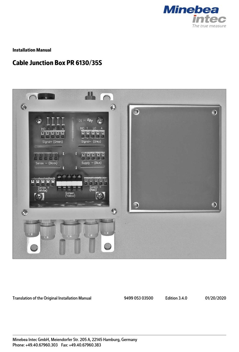
Minebea Intec PR 6130/04N User manual
Minebea Intec
Minebea Intec PR 6130/68S User manual

Minebea Intec
Minebea Intec PR 6130/65S User manual
Minebea Intec
Minebea Intec PR 6130/34Sa User manual