CHAOS CLANK User manual

Chaos manual // v 1.1

2
Table of contents
1. Introduction............................................ p.3
2. The Concept............................................ p.4
• 2.1.Mainfeatures
• 2.2.NewFirmwareadditions
3. Getting started....................................... p.5
• 3.1.Hookingupthemodule
• 3.2.Dimensions
• 3.3.Powerconsumption
• 3.4.SafetyInstructions
• 3.5.Warrantypolicy
4. Panel Overview....................................... p.6
5. Channel setup......................................... p.7
• 5.1.Inputassign
• 5.2.Channelreset
• 5.3.SettingsCopy&Paste
• 5.4.ChannelRun/Stop
• Time Control............................................ p.8
• 6.1.Clocksync
• 6.2.Probabilty
• 6.3.Width
• 6.4.Racheting
• 6.5.Time
• 6.6.Taptempo...............................................p.9
• 6.7.Swing
• Voltage control........................................ p.10
• 7.1.Voltagewindow
• 7.2.Groundtranspose
• 7.3.CVINGroundtranspose
• 7.4.Slewing
• 7.5.ScaleQuantization................................p.11
• 7.6.Rootnoteselection
• 7.7.CVINSample&Hold
6. Looping..................................................... p.12
• 8.1.LoopIN.......................................................p.13
• 8.2.Loopdirection
• 8.3.Loopcounterreset
7. Chaos Function...................................... p.14
• 9.1.ChaosIN
8. Save/recall.............................................. p.15
• 10.1.CVINslotrecall
• 10.2.Automaticslotrecallatstartup
9. Manteinance........................................... p.16
• 11.1.Calibration
• 11.2EEPROMerasing
• 11.3. Firmware update (Windows and Mac
users)
• 11.4Firmwareupdate(Linuxusers)...........p.17

3
Thank you for purchasing Chaos,
for us, designing this module has been a big step ahead from both a technical and intellectual point of view,
but, since we’ve always had a clear vision of how this module should be , nothing stopped us from studying and
working hard on it all the time. No matter how challenging it proved to be.
That’s why we hope you’ll enjoy it as much as we did when creating it!
Finally,
a special thanks goes to:
Our families, partners and friends for the support, Samuele Nigro (a.k.a. Fluize), Dan Sanfufano (whose real name
is yet to be known), Luca Romanelli (a.k.a. Mastrovalvola Pedals), Alessio Bianchi (AB elettronica) Enrico Corsi and
Robert Bardi.
A special mention also goes to all the beta testers who helped with their feedback on the new Firmware updates.
1. Thanks!

4
2. The concept
What is Chaos for real?
Chaos is the hidden force that moves everything
around us. It’s a random stream of events, whose
correlation is impossible to understand.
Even if its presence is a living paradox in our life, we
are used to inuence chaos in a very deterministic
way by setting the limits of its dynamic behavior:
in this way we can predict events and make them
possible.
We can set steady points, enclose them into
cycling loops and then make them work for us as
laws.
That’s exactly what our Chaos does.
A continuous stream of gates and voltages is
produced by a sophisticated random engine
controlled by a series of parameters that can be
set to dene its acting behavior.
Chaos is a six-channel aleatoric brain where a
random generator helps you quickly nalize your
idea. You can start from an extremely random and
uncontrolled mood but easily shift towards a more
deterministic and manageable atmosphere with
just one-click.
It’s like shaping a block of stone.
2.1. Main features. Chaos was conceived to be
the fulcrum of your system providing:
• An extremely wide range (10ms/10s) and
stable master clock
• 6 gate outputs with independent probability,
width and time control (synced or completely
independent from the master clock)
• 6 voltage outputs with independent
quantization, slew, random voltage window
selection and ground transpose
• For each channel there’s the option of using
the internal random generator or sampling an
external incoming voltage
• Individual channel looping capability
• 60 save and recall slots with no lag (also
under CV control)
• The ability to randomize all the parameters of
any channel on its own or in group with the
entropy control setting
• 3 External gate inputs for external clock/start
and stop, looping and Chaos function,
• 1 CV input for external voltage mirroring,
scale transposing, saved slots recall.
With all these functions combined together, Chaos
is pretty exible and can be easily used as a really
powerful multi-channel Turing machine, drum
sequencer, modulation generator, clock source,
voltage recorder and can perform many other
tasks.
Even if we’re in a pure digital domain, the random
generation feeling, and the design are pretty
analog. Chaos has been designed with playability
in mind: all parameters are always readable and
immediately available with no menus or hidden
elements to be remembered.
2.2. New Firmware (v1.1) additions. If you have
correctly installed rmware v1.1, when the Chaos
module is powered up, the initial LED ash should
be red, whereas rmware v1 will ash white.
This are the main additions:
• Channel settings Clear
• Channels Copy&Paste
• Channels Run/stop
• Time Swing function
• Tap tempo
• Time Racheting
• Adjustable slew limiting
• CV IN transpose
• Two new sets of quantized scales
• Root note selection
• Loop direction
• Loop counter reset
• Inbeetween 1-32 loop steps selectable
• Indipendent entropy amount for each modier
• Last saved slot recall at startup
5
3. Getting Started
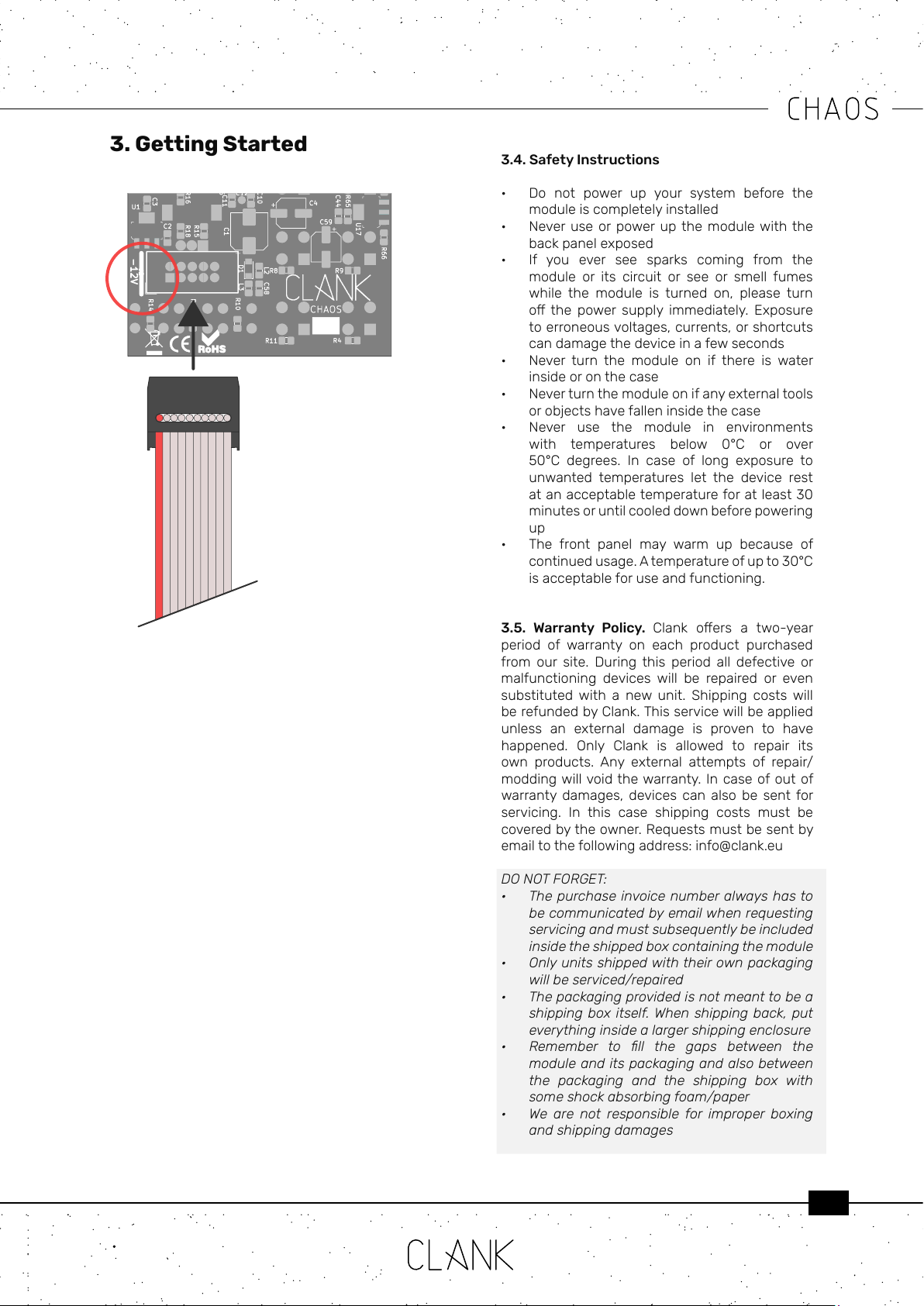
3.1 Hooking up the module. Make sure your
system is turned o, then connect the module to
the power bus using the ten to sixteen IDC cable
provided. The red line on the cable corresponds
to the -12V power rail. On the back of the module
a thick white line indicates where the -12V rail is
located on the IDC connector.
Before powering up make sure to have completely
installed the module by using the four panel screws
provided. Devices must stay rm inside their case.
Make sure the back is not touching other objects
inside the case. The exposed electronics may
cause shortcuts when coming into contact with
other electronic surfaces or objects.
3.2. Dimensions.
12Hp
3.3. Power Consumption.
+12V: 115mA
-12V: 0mA
+5V: 0mA
3.4. Safety Instructions
• Do not power up your system before the
moduleiscompletelyinstalled
• Never use orpowerup the modulewith the
backpanelexposed
• If you ever see sparks coming from the
module or its circuit or see or smell fumes
while the module is turned on, please turn
o the power supply immediately. Exposure
toerroneousvoltages,currents,orshortcuts
candamagethedeviceinafewseconds
• Never turn the module on if there is water
insideoronthecase
• Neverturnthemoduleonifanyexternaltools
orobjectshavefalleninsidethecase
• Never use the module in environments
with temperatures below 0°C or over
50°C degrees. In case of long exposure to
unwanted temperatures let the device rest
atanacceptabletemperatureforatleast30
minutesoruntilcooleddownbeforepowering
up
• The front panel may warm up because of
continuedusage.Atemperatureofupto30°C
isacceptableforuseandfunctioning.
3.5. Warranty Policy. Clank oers a two-year
period of warranty on each product purchased
from our site. During this period all defective or
malfunctioning devices will be repaired or even
substituted with a new unit. Shipping costs will
berefundedbyClank.Thisservicewillbeapplied
unless an external damage is proven to have
happened. Only Clank is allowed to repair its
own products. Any external attempts of repair/
moddingwillvoidthewarranty. Incaseofoutof
warranty damages, devices can also be sent for
servicing. In this case shipping costs must be
coveredbytheowner.Requestsmustbesentby
emailtothefollowingaddress:info@clank.eu
DO NOT FORGET:
• The purchase invoice number always has to
be communicated by email when requesting
servicing and must subsequently be included
inside the shipped box containing the module
• Only units shipped with their own packaging
will be serviced/repaired
• The packaging provided is not meant to be a
shipping box itself. When shipping back, put
everything inside a larger shipping enclosure
• Remember to ll the gaps between the
module and its packaging and also between
the packaging and the shipping box with
some shock absorbing foam/paper
• We are not responsible for improper boxing
and shipping damages
6
4. Panel overview
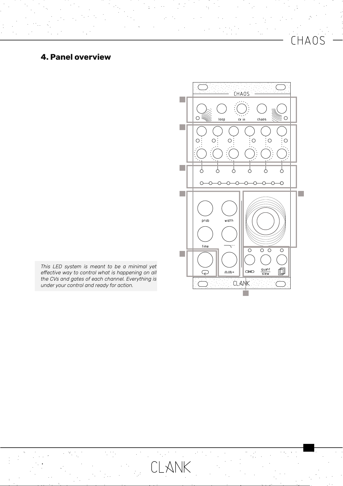
First row. On Chaos’ rst row, from left to right,
there are four inputs and one output:
• Clockin: gate trigger/input
• Loopin: gate trigger/input
• CVin: 0-8V CV input
• Chaosin: gate/trigger input
• Clockout: 8V gate output
Second and third row: Outputs
• In the middle row there are six gate outputs,
one for each channel. The gate high state
level is 8V and a dedicated LED blinks every
time a gate signal is sent.
• Under those you have the six corresponding
CV outputs (0v-8v) .
The LED bars. There are two LED bars on the
module, one with six LEDs and the other one with
ten [3].
• The rst one is the channel bar; it indicates the
selected channel in red and reects its real
time CV intensity by changing LED luminosity.
• The ten LED bar is the value bar, and it is
mainly thought for editing purposes. Press
any button to show the parameter value. By
default, if nothing is pressed it will display the
current channel’s CV output value.
This LED system is meant to be a minimal yet
eectivewaytocontrolwhatishappeningonall
theCVsandgatesofeachchannel.Everythingis
underyourcontrolandreadyforaction.
Encoder. To change the selected channel, simply
rotate the encoder without pressing any other
button.
When you reach the limit on the right all the LEDs
will become red, meaning you have selected all
the channels together. In this way you can easily
loop or change a modier or conguration at the
same time for all the channels.
The Modiers. The ve black buttons on the
bottom left are the modiers.
Hold down a modier to see the corresponding
value, rotate the encoder to change the value and
release the button when you are done .
The Loop button. The white button is used to
enter the loopmode. (p.12) .
Global settings. To access to channels global
settings three small buttons placed under the
encoder. Their name came reects their macro
functions wich are respectively:
• Inputassign
• Scalequantization/slewing
• Memoryaccess
1
2
3
45
6
7

7
2
1 4
5. Channel Setup
5.1. Inputs assign. Before starting to play with
Chaos a suggested routine is to give a check to
each channel settings by pressing on the Input
assignbutton[1].
This button, indeed, will show if the four inputs at
the top of the module are linked to their relative
function or not. In this way, they can be activated
or controlled, on the selected channel, thru
external gates or CVs.
To change a channel’s settings, hold the button
[1], on the value bar, the rst four LEDs on the left
[2] will glow representing each one of the four
inputs respectively.
Rotate the encoder CW or CCW to select an LED
and press it to change its status. A white LED will
indicate a non active link. Otherwise it will glow in
green except for CV in wich has other two dierent
status, red and orange (see pag 10-11).
5.2. Channel reset. To reset a channel to it’s
default values, double tap on the Memoryaccess
button [4]. The corresponding LED will blink
briefely and, all the modiers values and channel
settings will be restored.
To reset only the loop modiers, hold the loop
button while double tapping.
If all the channels are selected, then all the
channelswillberestoredtotheirdefaultvalues.
5.3. Copy & Paste. To copy all the channel
settings, hit the Memoryaccessbutton [4] once.
The corresponding LED will light up and all the
informations will be copied into the memory buer.
Select another channel with the encoder and hit
the Save/recall/channel reset button again. The
LED will turn o and everything will be copied to
the new channel.
Everytimeyoupasteachannelsettingstoanother
the memory buer will be erased so. To copy
the same informations to more than a second
channel the whole process has to be repeated
eachtime.Otherwise,ifallchannelsareselected
when pasting, every channel will end with the
sameinformationscopied.
5.4. Channel Run/Stop. To access this function
double tap on the Input assign button [1]. Now,
each one of the modiersbuttons (plus loop) [5]
corresponds, respectively, to each one of the six
channels. (Ch.1 is Probability, Ch.2 is Width, Ch.3 is
Time and so on..).
Press one of these to activate or mute its
corresponding channel.
An orange LED on the channel bar will indicate
wich one is active.
Press the Channelsettingsbuttonto go back to
the mainpage. If muted, a channel will now appear
as pale orange on the channel bar.
Iftherstchannelisunsyncedandthereforewill
actasmasterclock,whenmuted,allthesystem
will stop. Inthis way it can double up as global
Start’n’stopcommand.
5
8
6. Time Control
At its core, Chaos is composed of six channels
of clock generators [2] and all the channels can
be individually synced to the master clock or be
completely time independent.
To change this press the Channelsettings button
[6] and rotate the encoder to select clockin LED
[1]. When green, it will be linked to the master
clock, when white, it will be unsynced and time
independent.
6.1. Clock sync [1]. If no signal is applied to the
Clockinput[1], Channel 1 will be the master clock.
To sync Chaos to an external clock source, send a
50% pulse width gate to Clockinput[1]. A trigger
or a LFO may be also inserted.
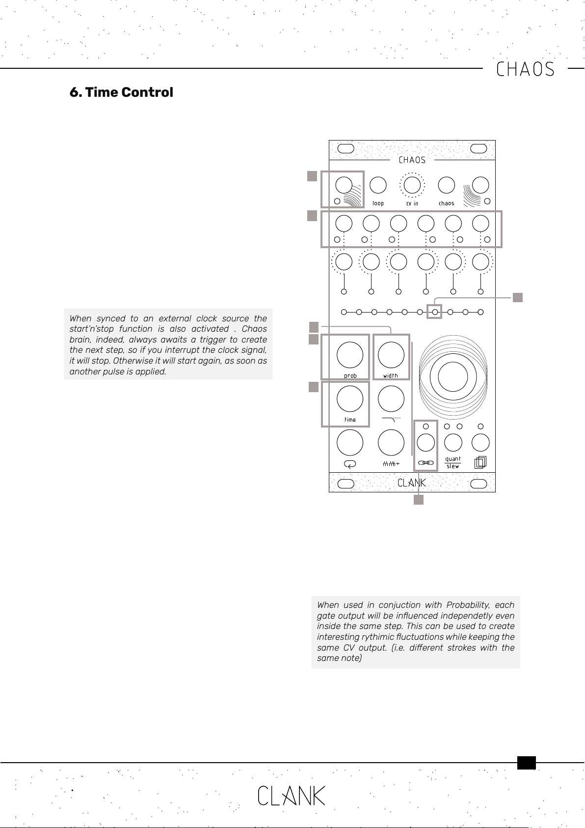
When synced to an external clock source the
start’n’stop function is also activated . Chaos
brain, indeed, always awaits a trigger to create
thenextstep,soifyouinterrupttheclocksignal,
itwillstop.Otherwiseitwillstartagain,assoonas
anotherpulseisapplied.
6.2. Probability [3]. This function is a sort of coin
toss to declare if a gate of the selected channel
will re or not.
Changing the probability value will reduce its
possibility to happen. The range of value is from
0% to 100%.
If you’re using channel 1 as the master clock,
changing itsprobability will aect its gate output
but not the master clock data stream.
Turn it to zero will also mute a channel.
6.3. Width [5]. The length of a gate’s duty cycle
expressed in percentage. Range is from 1% to
100% (fully open).
6.4. Racheting [5]. This function allows to multiply
the number of emitted gates for each step.
This means that inside the same time lenght
more than one gate can be played and their time
distance will be a fraction of the initial interval.
To access this function, tap and hold the width
button [5] , on the value bar 8 white LEDs will
indicate all the the possible divisions.
The orange LED will show wich ratio is selected,
2
1
3
4
5
rotate the encoder to change it beetwen 1:1 and
8:1.
Gate width will be eected at the same manner,
meaning that each dot on the value bar will also
halve the gate lenght.
When used in conjuction with Probability, each
gateoutputwillbeinuencedindependetlyeven
insidethesamestep.Thiscanbeusedtocreate
interestingrythimicuctuationswhilekeepingthe
same CV output. (i.e. dierent strokes with the
samenote)
6.5. Time [4] is expressed in two dierent ways,
depending on if a channel is synced or not:
6
7
9
If the selected channel is synced to the
master clock the Time button will let you set a
multiplication or division of the master itself. The
pulse of the two-central LEDs on the main bar
means that the channel is at the same rate of the
master clock.
Rotating the encoder CW multiplies it (LEDs in
white), CCW divides it (LEDs in orange) and the
available multiplications and divisions are from 1
to 8, then from 16 to 32.
If the selected channel is the master or if it’s not
synced to the clock, time will be expressed in
milliseconds between two consecutive gates.
You can easily change it by pressing time and
turning the encoder. Rotating it CCW will result in
a faster clock, whereas rotating CW will make the
clock slower (this is because you will be reducing
or augmenting the milliseconds between two
consecutive gates).
When un-synced, default value beetween each
gate is 500ms (120bpm) while time range goes
from 10ms to 10 seconds.
In the rst window, in white, every LED corresponds
to 100ms each step. By reaching the upper limit
you will enter a second window in blue. Here every
LED corresponds to 1 second.
KeepinmindthatChaoscanemitgatesfromone
every 5.5 minutesto audio band (approximately
100hz)sotimingchangescanbeverydrastic.
6.6. Tap Tempo. When a channel is un-synced,
another cool feature is the tap tempo ability.
Just tap on the Time button and the clock will
automaticaly set to the tapped tempo.
6.7. Swing. When synced each Chaos channel
can be shifted in time for a fraction of the master
clock rate to easily achieve upbeats.
To change swing settings:
• Tap and hold the Timebutton[4]
• On the value bar, the four LEDs on the left are
rapresenting the channel swing to the master
clock.
• Rotate the encoder to choose the delay
beetween 0, 1/4, 2/4 or 3/4 and press to
select the desired value. The selected one will
light up in orange while, the not selected ones
will be white.
10
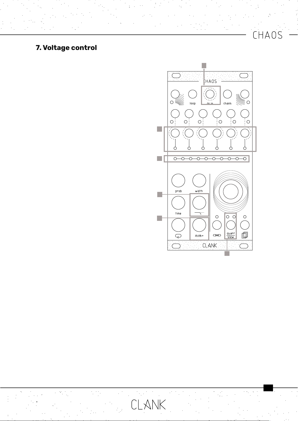
Along with its internal clock generator Chaos
engine is composed of six channels of randomic
voltage generators. By default every time a gate
rises up a new random voltage from 0 to 8v will
be available on the CV output of that channel [1].
On the value bar [6] each LED corresponds to 1 volt
step. The LED intensity will also reect the value
inbeetween voltages. In this way the nal output
value will always be easy to understand and read.
Since a span of 8V is quite a lot (especially when
controlling the pitch of a VCO) some useful
controls have been created to limit the range of
action.
7.1 Voltage window [2]. , This control reduces the
upper limit of values that the generator can pick.
When pressed, the value bar [6] will turn to white
and it will express how many volts of range to
select. If the whole range is selected, the eight
LED will ash in orange.
7.2. Ground transpose [3]. With this modier you
can shift the window of values that the generator
can pick. It’s like setting its lower limit.
Press the button and rotate the encoder, the more
you turn and more your lower limit will be shifted
from 0V to a higher base level. Counting how
many dark LEDs from the right will indicate the
new transposed ground level.
When not quantized every encoder dent will
increase the ground voltage by a semitone (1V/12).
When quantized on a particular scale, instead, the
ground transpose will work dierently. Turning the
encoder, infact, won’t change the output value
untill the next note of the scale is reached.
7.3. CV IN transpose. This feature permits to
control the ground transpose function with an
external voltage source. In this way tonal jumps
can be controlled in a more deterministic way thru
the CV IN input [5].
To access to this function, go to the Inputassign
menu and rotate the encoder to the right on the
third LED. Then press untill it goes red. Now CV IN
transpose is applied on that channel.
7.4. Slewing. For a more uid transition beewteen
7. Voltage control
1
2
3
output voltages slewing can be activated.
To apply slewing to the selected channel, press
the quant/slew button once [4].
The corresponding LED will light up in white to
indicate that.
To adjust the lenght of the transition just tap and
hold the quant/slewbutton.
The value bar will now express a percentage
referred to the whole step duration.
This means that with 100% of slew, the CV will
keep all the step lenght to reach the new value.
5
6
7

11
7.6. Root note selection. Since every quantization
option is referred to the C note, changing the
root could be handy to adjust the Chaos’ output
voltages to a specic intonation.
To do this hold the quant/slew button and
then press and hold down the encoder. On the
value bar the rst LED will be in white and it will
represent the C note. Rotate CW while keeping it
pressed and the whole output will be shifted by
a semitone every dent increase. Each white LED
will be one of the seven keys while red LEDs will
represent sharp notes.
7.7. CV IN Sample & Hold. Thanks to its dedicated
input an external voltage can be used in place
of the random generators. In this way, Chaos
will produce, a sample and hold of the external
voltage source.
To activate this option, select the desired channel,
hold the Channel settings button, rotate the
encoder to select the third LED (wich, by default
is in white) and then press the knob. Now the light
will turn to green, meaning that the CV IN mode is
active on that channel.
To go back to the internal generators, press it
again twice. First press will turn it to red (CV
transpose mode) and the second will go back to
white (random mode).
Evenwhensamplinganexternalvoltage,allthe
voltagemodiersandquantizingmodeswillwork
the same as with random voltages. In this way
precise melodic lines can be edited or created
fromanLFOorenveloptoo.SincetheexternalCV
oscillations can’t be predicted, Slewing, instead,
won’tworkinthiscase.
7.5. Quantization. Chaos can quantize voltages to
a dened scale transforming its chaotic behaviour
or an external source to a more melodic one.
To choose a scale, hold the quant/slew button and
turn the encoder to scroll between them. To select
a scale simply release the button.
The left quant/slew LED will stay on indicating the
current scale’s color. While keeping quant/slew
pressed, the current scale will be shown blinking
on the value bar as well.
There are three sets of modes. Each time you
reach the end of a set turning the encoder CW will
make it skip to the next set and vice versa.
The rst set includes 10 basic scales, the second
set includes the 7 modes of the melodic major
scale, and the third set includes the 7 modes of
the melodic minor scale.
First set:
• Unquantized (Default)
• Chromatic
• Octave
• Major pentatonic
• Minor pentatonic
• Blues
• Arabic
• Pelog
• Hirajōshi
• Chinese
Second set:
• Ionian
• Dorian
• Phrygian
• Lydian
• Mixolydian
• Aeolian
• Locrian
Third set:
• Ascending melodic minor
• Dorian b2
• Lydian augmented
• Lydian dominant
• Mixolydian b6
• Locrian #2
• Super Locrian
12
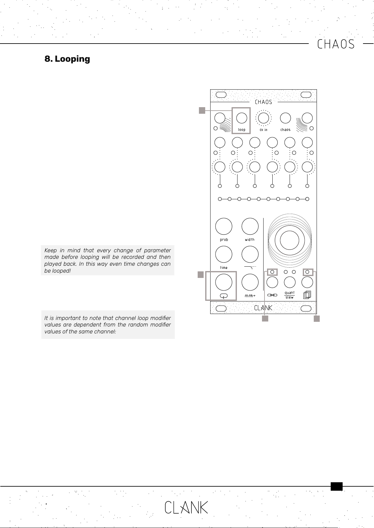
All six channels have an independent looping
capability. At all times, Chaos is keeping the last
32 steps memorized.
To start a loop, press the white loopbutton once
[1]. The value bar and the input assign [2] LED
will turn blue. Chaos is now in a loop that reects
everything that happened in the last steps.
The loop length can be changed by holding down
the loopbutton and by rotating the encoder, the
number of steps will be shown as 8 yellow dots on
the value bar.
Four pages of 8 steps, are then used to show the
steps and the 9th and 10th LED will indicate wich
page you are in.
• When Both OFF, rst page (step 1-8).
• 9th LED ORANGE , second page (step 9-16),
• 10th LED ORANGE, third page (step 17-24).
• both LEDs RED, step (25-32).
Press the loopbutton again to exit from this mode.
Keep in mind that every change of parameter
made before looping will be recorded and then
playedback.Inthiswayeventimechangescan
belooped!
Whether Chaos is in loop mode or not, the
recorded sequence can be altered by holding the
loop button together with one of the ve modier
buttons.
Itisimportanttonotethatchannelloopmodier
valuesaredependentfromthe randommodier
valuesofthesamechannel:
• The loop’s probability modier works within
the probability percentage of the channel’s
original probability value. That is to say that
if the channel’s original probability is at 70%,
that will be the loop’s probability maximum
value
• The loop’s width will increase or decrease the
lenght of the original random width value.
On the ten LED bar the original value is placed
at the center and if rotating to to the left it will
decrese its lenght. Viceceversa when going
to the right it will increase untill the maximum
is reached.
• The loop’s time modier works as a multiplier/
divider of the channel’s original random time
value
8. Looping
1
2
• The loop’s voltagewindow modier value works
similarly to probability, and therefore can only be
decreased from its original non-looped value
• The loop’s groundtranspose value works similarly
to width, and therefore can be increased or
increased from its original non-looped value
keeping the two central LEDs as reference point
to the original value.
To reset loop values to their original state hold the
loop button, and then double tap on the memory
accessbutton. This way you can easily transpose a
loop or modify its timing and return to the initial loop
settings in a moment.
3
3

13
Pleasenotethatchangingtheoriginalparameters
ofthechannelwhilethechannelisinloopmode
will not alter the loop’s starting values, as loop
memorizesastateandoperatesonthosevalues
untilit’sdisabled.
8.1. Loop IN. Loop mode can also be activated by
sending a gate to its dedicated input [3]. In this
case, the eight LED on the input assign menu has
to be green.
With this workow, looping can be even more
expressive than just recording. It could be thought
of as a pre-determined variance to the whole
random generation!
8.2. Loop direction. When in loop mode, the
direction of the recorded sequence can be
inverted on the y.
To access this function, hold the loop button: if
the sequence is running forward, the LED over the
Memory access button will be ON. Viceversa, if it’s
going backwards, the one over the Input assign
button will be lit.
To change direction, simply press the
corresponding button .
8.3. Loop counter reset. When in loop mode,
the recorded sequence can be reverted back to
its initial step to achieve cool live eects or just to
understand wich one is the rst note.
To do this, hold the loop button and then press
the quant slew button. Each press, the looped
sequence will restart from its beginning.
14
Every time you press the encoder , Chaos will re
up and the inputassign LED will blink in purple.
Each time every modier value will be randomized
creating a new mood.
Since Chaos’ limits are very vast, changes can be
quite drastic, that’s why entropy factor is pretty
useful: it represents the percentage of how much
the new value can variate from the one you have
set. Create subtle dierences or completely
distant moods.
Entropy can be set independently on each channel
or on one or more of each channel’s modiers. To
change the channel’s entropy, hold down and
rotate the encoder [2] CCW to reduce entropy, turn
it CW to increase it. The entropy percentage can
be visualized on the value bar.
To change a channel modier’s entropy, hold a
modier and the encoder at the same time, then
rotate the encoder CCW to reduce entropy, turn it
CW to increase it. The entropy percentage can be
visualized on the value bar.
When a channel modier’s entropy value is
changed it overrides the channel entropy value
when chaos is activated. When a channel’s general
entropy is changed it assigns that value to every
modier equally.
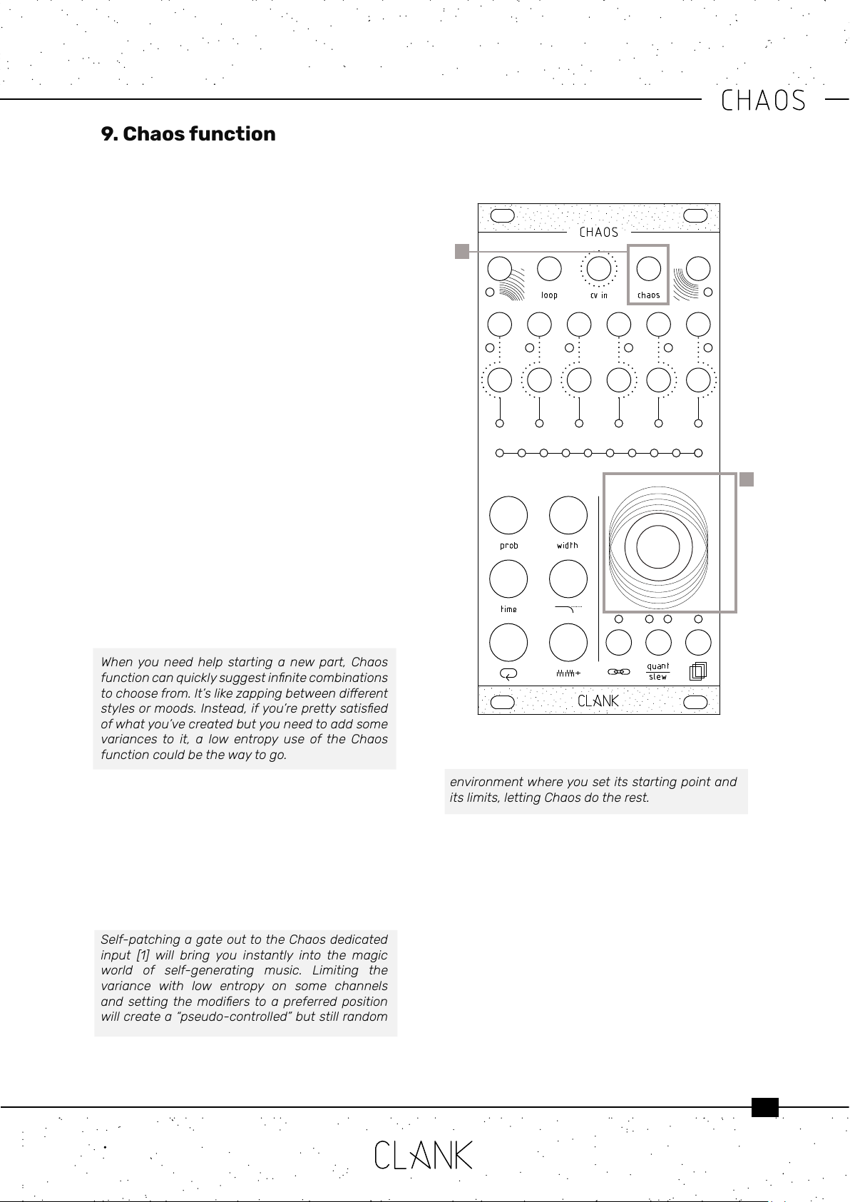
Whenyouneed helpstarting anewpart,Chaos
functioncanquicklysuggestinnitecombinations
tochoosefrom.It’slikezappingbetweendierent
stylesormoods.Instead,ifyou’reprettysatised
ofwhatyou’vecreatedbutyouneedtoaddsome
variancesto it, a low entropy use ofthe Chaos
functioncouldbethewaytogo.
9.1. Chaos IN. Chaos function can also be
activated sending a gate to its dedicated input [1].
In this case every channel linked to this input
will be hit be Chaos each time a gate is sent.
Individual entropy settings will be keep intact.
To assign or avoid this input to a channel , go to
Channel settings menu and ip the status of the
second LED on the left.
Self-patchingagateouttotheChaosdedicated
input [1] will bring you instantly into the magic
world of self-generating music. Limiting the
variance with low entropy on some channels
andsettingthemodierstoa preferredposition
willcreatea“pseudo-controlled”butstillrandom
9. Chaos function
1
2
environmentwhereyousetitsstartingpointand
itslimits,lettingChaosdotherest.
15
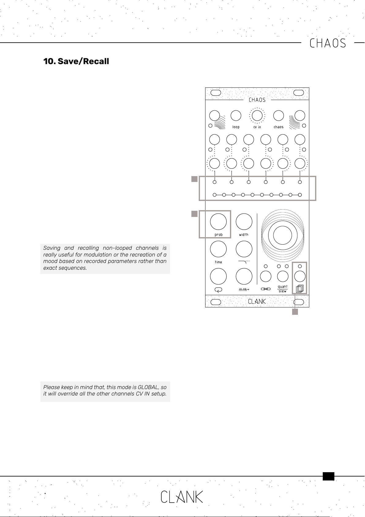
Six banks of eight slots each are available for
saving.
Hold down the save/recall button [1] to access
the save/recall menu. The channel bar indicates
which one of the six banks is selected, while the
value bar indicates the slots [2].
Turn the encoder to select the slot you prefer, after
the tenth one you’ll skip to the next bank.
Press the encoder to save a slot, release the save/
recallbutton to load one of the available slots.
The white LEDs on the value bar will indicate the
already saved slots.
Press the probability button [3] to clear the
selected slot. Recalling an empty slot will not have
any eects on your session.
When saving, an exact picture ofwhat is happening
at the moment will be taken and every channel will
be saved in its current state: if a channel is looped,
the sequence with all its modiers will also be
recorded. If muted, the channel will be saved as is.
Saving and recalling non-looped channels is
reallyusefulformodulationortherecreationofa
moodbasedonrecordedparametersratherthan
exactsequences.
10.1. CV in slot recall. This function can be used to
scroll beetween the ten saved slots of each bank
transforming Chaos into a complete sequencing
machine.
To achieve that go to the Channelsettingsmenu
by pressing the dedicate button, then, rotate the
encoder to the third LED on the value bar and then
press the knob for few seconds.
The LED color will turn to orange and now this
function is activated. Sending a CV from 0V to
8V will move you thru the saved scenes of the
selected bank with increments of 1V each slot.
Pleasekeepinmindthat,thismodeisGLOBAL,so
itwilloverridealltheotherchannelsCVINsetup.
10.2. Automatic slot recall at startup. When
saved slots are present, at the startup, Chaos will
automatically recall the last saved or used one. In
this way it will restart exactly from where it was
left the last time before turning it o.
1
2
3
10. Save/Recall

16
11. Manteinance
11.1 Calibration
Chaos CV outs are already calibrated by factory. If in some way the internal DACs scaling needs to be adjusted,
that can be done by following this procedure:
• Hold down the encoder while powering up the module.
• After the initial LED transition they all will turn purple.
• Now you can release the encoder and the rst channel LED will be selected.
• Connect the channel CV output to a multimeter.
• Turn the encoder untill you read a steady 8V voltage.
• When the rst channel is calibrated, press the encoder and it will skip to the next channel. Repeat that for
every channel and when the last one is set Chaos will go back to standard operation mode.
11.2 EEPROM erasing
Pressing the probability button while on the calibration process will erase Chaos EEPROM. All the savings will be
then erased.
ATTENTION:WhenupgradingfromFirmwarev1.0tov1.1,erasingtheEEPROMismandatory!Sincesavingslots
willbeallocatedinanotherregionofthememory,tryingtoloadthemwill,otherwise,makethenewFWcrash.
11.3 Firmware Update (Windows and Mac users)
To update your Chaos just follow these easy steps:
• First, go to https://www.silabs.com/developers/usb-to-uart-bridge-vcp-drivers and click on the Downloads
tab. Download and install the “CP210x Driver” compatible with your device.
• Next, go to https://www.st.com/en/development-tools/stm32cubeprog.html#get-software and download
and install the “STM32CubeProgrammer” le compatible with your device. [Please note that to download the
software you will have to have an st.com account or leave your name and email address. There are no fees
to register and download.]
• Finally, go to https://www.clank.eu/chaos and download the rmware .bin le from the link at the bottom of
the page.
IMPORTANT:Atthispoint,pleasemakeabsolutelysurethatyourChaosmoduleisNOTattachedtoanykindof
powersource.
• Connect the micro-USB end of a micro-USB/USB cable to Chaos. While holding down the BOOT button [next
to the micro-USB port on the backside of the module], insert the USB end of the cable into your computer.
Once this is done you may release the BOOT button.
• Next, open the Cube programmer. Select UART, and the correct port. On MAC devices it should appear as “cu.
SLAB_USBtoUART”. On Windows it is usually the COM port with the highest number. If the port should not be
listed, try refreshing the port list. If this doesn’t work as well, try repeating the boot process.
ForMACuserswithMacOS10.13(HighSierra)orlater,installingrequiressomefurtheractions:
EvenifpassedbyMacOSgatekeeper,itwon’tlaunch.Toavoidthat,gotothedownloadedapp(showpackage
content>contents>macos>SetupSTM32CubeProgrammer-2_8_0_macos) and launch it withTerminal. At this
point,installationshouldrunne.
• Once you have selected the correct port, click on “Connect”. Your device should be recognized immediately.
• Next click on “Open le”. Find the rmware’s .bin le and open it. Click on “Download” and the rmware should
be installed within seconds. Click on “Disconnect” and you’re all done.

17
11.4 Firmware Update (Linux users).
This is the guide as posted by “drredesign” on ModWiggler Chaos page. While we can’t verify it, we would like to
thank him for his big contribute, and if you nd it useful, go on the discussion page and say thanks to him!
(https://modwiggler.com/forum/viewtopic.php?t=241187&start=125)
• Check if your kernel was already distributed with the appropriate drivers:
CODE:SELECTALL
$locatecp210
/usr/lib/modules/5.11.0-7614-generic/kernel/drivers/usb/serial/cp210x.ko
/usr/lib/modules/5.11.0-7620-generic/kernel/drivers/usb/serial/cp210x.ko
/usr/lib/modules/5.11.0-7633-generic/kernel/drivers/usb/serial/cp210x.ko
/usr/lib/modules/5.13.0-7614-generic/kernel/drivers/usb/serial/cp210x.ko
/usr/lib/modules/5.13.0-7620-generic/kernel/drivers/usb/serial/cp210x.ko
/usr/lib/modules/5.15.23-76051523-generic/kernel/drivers/usb/serial/cp210x.ko
/usr/lib/modules/5.15.5-76051505-generic/kernel/drivers/usb/serial/cp210x.ko
/usr/src/linux-headers-5.11.0-7614-generic/include/cong/usb/serial/cp210x.h
/usr/src/linux-headers-5.11.0-7620-generic/include/cong/usb/serial/cp210x.h
/usr/src/linux-headers-5.11.0-7633-generic/include/cong/usb/serial/cp210x.h
• If you have any output ending in cp210x.h or cp210x.ko you should be ne to proceed. Otherwise you will need
to sign up for an account on Silicon Labs as they do not provide Linux downloads without actual account
creation. There are no fees to register and download. Click in the link in the previous Mac and Windows section
to get started.
• Device Programmer: Download and install the STM32CubeProgrammer version compatible with your device.
Please note that to download the software you will have to have an st.com account or leave your name and
email address.
• Firmware Files: Finally, go to https://www.clank.eu/rmware-download and download the rmware .bin le
from the appropriate link.
• Connect your module:
IMPORTANT:Atthispoint,pleasemakeabsolutelysurethatyourChaosmoduleisNOTattachedtoanykindof
powersource.
• Connect the micro-USB end of a micro-USB/USB cable to Chaos. While holding down the BOOT button [next
to the micro-USB port on the backside of the module], insert the USB end of the cable into your computer.
Once this is done you may release the BOOT button.
NOTE:Youneedtomakesureyouruserispartoftheappropriateusergroupinordertoconnecttoyourdevice.
Onceyouhaveconnectedyourdevice,checkfortheownergroupofthedeviceyouhaveconnected.Thisis
probablygoingtobethedialoutgroup,butyourdistromaybedierent.
CODE:SELECTALL
$ls-la/dev/ttyUSB0|cut-d’‘-f4
dialout
• If you are already part of the appropriate group it will be listed in the output of the groups command:
CODE:SELECTALL
$groups
usernamedialoutsudoplugdev

18
• If you do not see the same group, you need to add yourself to that group and then restart your computer. You
cannot just log out and back in. To add yourself, use the following command:
Beverycarefulwiththiscommand!YouneedtobePOSITIVEtoinclude-aoryouwillremoveyourselffromthe
sudogroupandwillnotbeabletoinstallanything.
CODE:SELECTALL
$sudousermod-a-Gdialoutusername
• Make sure to replace dialout with whatever group your system reports is the owner of your ttyUSB device.
Finally, if you did change your groups, you will need to restart your computer. You cannot just log out and
back in.
• And seriously, if you do not include -a you are going to completely lock yourself out of your system. You can’t
install updates, you can’t change anything not directly owned by your user, you can’t add yourself back into
sudo. I did this one time and I just simply had to wipe my computer do a fresh install. I do not recommend it.
• Writing the Firmware: Open the STM32CubeProgrammer application. Linux users may need to open it from
the command line:
CODE:SELECTALL
$ ~/path/to/unpacked/archive/STMicroelectronics/STM32Cube/STM32CubeProgrammer/bin/
STM32CubeProgrammer
Abovetherighthandpanel,selectUART,andthecorrectport.TheportwillbenamedaccordingtoyourOperating
• System: on Linux devices it should be a ttyUSB port and an associated number, for example:
CODE:SELECTALL
ttyUSB0
• If a port is not listed, try refreshing the port list. If this doesn’t work, unplug the USB cable and try repeating
the boot process.
• Once you have selected the correct port, click on “Connect”. Your device should be recognized immediately.
Next click on “Open le”. Find the rmware’s .bin le and open it. Click on “Download” and the rmware should
be installed within seconds. Click on “Disconnect” and you’re all done.
Table of contents
Popular Recording Equipment manuals by other brands


Paia
Paia 4780 Using

Studio Technologies
Studio Technologies StudioComm 780-01 user guide

cymatic audio
cymatic audio uTrack 24 quick start guide

AMX
AMX NetLinx Custom Panel Interface NXP-CPI16 Operation/reference guide

Keyautomation
Keyautomation SEL-D Instructions and warnings for installation and use

digi-tech
digi-tech DSP-256XL owner's manual