Baxall MDR Series User manual

Please read this manual before using the equipment
MDR Series Multiplexed Digital Recorders
User Manual
IntelligentSecurity&Fire

Page 2
MDR Series Multiplexed Digital Recorders User Manual
IMPORTANT
The first few pages of these instructions contain important information on safety and product
conformity. Please read, and ensure that you understand this information before continuing.
IntelligentSecurity&Fire

Page 3
User Manual MDR Series Multiplexer Digital Recorders
CONTENTS
Important Safeguards ................................................................................................................................................................................ 5
Damage Requiring Service ........................................................................................................................................................................ 5
Product Safet ............................................................................................................................................................................................ 6
Electromagnetic Compatibilit (EMC) ...................................................................................................................................................... 6
Regulator Notices ..................................................................................................................................................................................... 6
Manufacturers Declaration of Conformance .......................................................................................................................................... 6
Unpacking ................................................................................................................................................................................................... 6
Features, Connections and Setup
Product Description and Features ............................................................................................................................................................... 8
Associated Equipment ................................................................................................................................................................................. 8
Passwords .................................................................................................................................................................................................... 9
Rear Panel onnections .............................................................................................................................................................................. 9
Powering Up ............................................................................................................................................................................................... 13
Minimum Recommended Menu Setup ...................................................................................................................................................... 13
Basic User Operations
The Front Panel .......................................................................................................................................................................................... 15
Live Viewing ................................................................................................................................................................................................ 16
Playback ..................................................................................................................................................................................................... 17
Recording ................................................................................................................................................................................................... 18
Display Options .......................................................................................................................................................................................... 18
Active ameos ........................................................................................................................................................................................... 19
Sequencing ................................................................................................................................................................................................. 20
On-screen Indicators .................................................................................................................................................................................. 20
Triplex Mode ............................................................................................................................................................................................... 21
The Print Image Feature ............................................................................................................................................................................ 22
The Menu System ...................................................................................................................................................................................... 23
The Main Menu
Time/Date ................................................................................................................................................................................................... 25
Sequencing ................................................................................................................................................................................................. 27
Record ........................................................................................................................................................................................................ 28
Alarms ......................................................................................................................................................................................................... 33
Macro .......................................................................................................................................................................................................... 38
Motion Detection ......................................................................................................................................................................................... 39
amera Setup ............................................................................................................................................................................................ 41
Archive Setup ............................................................................................................................................................................................. 44
IntelligentSecurity&Fire

Page 4
MDR Series Multiplexed Digital Recorders User Manual
CONTENTS
Audio Setup ................................................................................................................................................................................................ 45
Telemetry .................................................................................................................................................................................................... 45
ommunications ......................................................................................................................................................................................... 47
Front Panel Lock ........................................................................................................................................................................................ 49
Factory Settings .......................................................................................................................................................................................... 49
Passwords .................................................................................................................................................................................................. 49
The QuickInstall, Operator and S stemView Menus
The QuickInstall Menu ................................................................................................................................................................................ 51
The Operator Menu .................................................................................................................................................................................... 51
The SystemView Menu ............................................................................................................................................................................... 51
Alarms
Alarm Input ................................................................................................................................................................................................. 56
Alarm Output .............................................................................................................................................................................................. 56
Alarm Acknowledge .................................................................................................................................................................................... 56
On-Screen Displays During Alarms ........................................................................................................................................................... 56
Alarm Operations During Playback ............................................................................................................................................................ 57
Alarm History Box ....................................................................................................................................................................................... 57
Searching
Disk Analysis Screen .................................................................................................................................................................................. 59
Quick Archive to D ................................................................................................................................................................................... 59
Motion Search ............................................................................................................................................................................................ 59
Search Filters ............................................................................................................................................................................................. 60
Search Results ........................................................................................................................................................................................... 61
WaveBrowser and WaveLink
WaveBrowser ............................................................................................................................................................................................. 63
WaveBrowser Layout and ontrols ............................................................................................................................................................ 64
WaveLink .................................................................................................................................................................................................... 65
Technical Specifications and RS232 Protocols
Technical Specifications ............................................................................................................................................................................. 67
RS232 Alarm/Event Generation and Text Insertion Protocol ..................................................................................................................... 68
RS232 Remote ontrol Protocol ................................................................................................................................................................ 70
Appendix: External Archiving Devices .................................................................................................................................................. 72
IntelligentSecurity&Fire

Page 5
User Manual MDR Series Multiplexer Digital Recorders
IMPORTANT SAFEGUARDS
This product is exclusively for use in CCTV applications and has no other purpose.
Read and Retain these Instructions - All the safety and operating instructions must be read before the unit is operated
and should be retained for future reference.
Cleaning - Unplug the unit from the supply outlet before cleaning. Use a damp cloth for cleaning. Do not use liquid or
aerosol cleaners.
Accessories - Do not use accessories that have not been recommended by the product manufacturer as they may cause
ha ards.
Water and Moisture -
Do not install this unit near sources of water.
For example, near a bathtub, wash bowl, kitchen sink, or
laundry tub, in a wet basement, near a swimming pool, in an unprotected outdoor installation, or any area that is classified as a
wet location.
Do not expose the unit to rain or moisture. Moisture can damage internal components.
Mounting During Installation - Do not place this unit on an unstable stand, tripod, bracket, or mount. The unit may fall,
causing serious injury to a person and serious damage to the unit. Any mounting of the unit should follow the manufacturers
instructions, and should use a mounting accessory kit supplied by the manufacturer.
Chassis: Other equipment may be placed on top of the unit if it weighs less than 35 pounds (16 kilograms).
Temperature: Observe the units operating temperature (0 to 40OC) and non-condensing humidity specifications (10% to
80%) when choosing a location for the unit. Extremes of heat or cold beyond the specified operating temperature limits
may cause the unit to fail. Do not install this unit on top of other hot equipment.
Ventilation - Install the unit in a well-ventilated area. Openings in the enclosure are provided for ventilation to ensure
reliable operation of the unit and to protect it from overheating. These openings must not be blocked or covered, and
therefore this unit should not be placed in a built-in installation unless proper ventilation is provided. Do not place directly
on other hot equipment, because this may increase its operating temperature.
Po er - Ensure that the sites AC power is stable and within the rated voltage of the 12V DC power supply. If the sites AC
power is likely to have spikes or power dips, use power line conditioning or an Uninterruptable Power Supply (UPS).
Po er-Cord Protection - Power-supply cords should be routed so that they are not likely to be walked on or pinched by items
placed upon or against them, paying particular attention to cords at plugs, and the point where they exit from the appliance.
Cable Runs - cabling of the unit must be in accordance with the country of installations national wiring regulations.
Object and Liquid Entry - This equipment must be protected from the ingress of foreign materials. Never push objects of
any kind into this unit through openings as they may touch dangerous voltage points or short-out parts that could result in
a fire or electric shock. Never spill liquid of any kind on the unit.
Servicing - There are no user-serviceable parts. Do not remove the covers as this may expose you to dangerous voltages
or other ha ards. Refer all servicing to qualified service personnel.
Replacement Parts - When replacement parts are required, an approved service agent must be used in order to ensure
any replacement parts used meet the specifications of the manufacturer. The use of unauthorised substitute components
may result in fire, electric shock or other ha ards.
Safety Check - Upon completion of any service or repairs to this unit, suitably qualified personnel must perform all relevant
safety checks to determine that the unit is in a proper and safe operating condition e.g. flash testing, PAT testing, etc.
Signal Cables Connected to 0V (signal ground) - Ensure connections to signal cable 0V are made in accordance with
the country of installations national wiring regulations to ensure safe operation and to minimise earth loops. This must not
be confused with the safety earth connection required for Class 1 equipment, i.e., equipment that must be connected to a
safety earth for safe operation.
Non-Use for Long Periods - If the unit is not to be used for long periods, it is recommended that input power, and all
interface cables are disconnected from the unit.
DAMAGE REQUIRING SERVICE
Unplug the unit from the outlet and refer servicing to qualified service personnel under the following conditions:
When the power supply cord or plug is damaged.
If liquid has been spilled, or objects have fallen into the unit.
If the unit has been exposed to rain or water.
If the unit does not operate normally by following the operating instructions.
If the unit has been dropped or the cabinet has been damaged.
When the unit exhibits a distinct change in performance.
If the unit has no power even when the power supply appears to operate correctly. If this is the case then ask a service
engineer to test the internal fuse.
IntelligentSecurity&Fire

Page 6
MDR Series Multiplexed Digital Recorders User Manual
PRODUCT SAFETY
Installation is only to be carried out by competent, qualified and experienced personnel in accordance ith the
country of installations National Wiring Regulations.
The unit contains no user-serviceable parts.
This unit contains a lithium battery hose expected life is in excess of five years. If the unit loses its settings
each time it is s itched off then the battery needs replacing. In this instance return the unit to the manufacturer
or manufacturers approved service agent ho ill replace the battery.
There is a danger of explosion if the lithium battery is incorrectly replaced. Replace only ith the same or an
equivalent type recommended by the manufacturer. Dispose of unused batteries according to the manufacturers
instructions.
The unit must not be used in a medical and/or intrinsically safe application and is intended for general purpose
CCTV applications only.
Do not exceed the voltage and temperature limits given in the specification. Only operate the unit in a clean, dry,
dust-free environment, pollution degree 2, overvoltage 2. Altitude not to exceed 2000m above sea level.
ELECTROMAGNETIC COMPATIBILITY (EMC)
This is a Class A product. In a domestic environment this product may cause radio interference in hich case the
user may be required to take adequate measures.
Radio Frequency Emissions
British standard BSEN50081-2:1994 Electromagnetic compatibility - Generic emission standard. Part 2. Industrial
environment.
British standard BSEN55022:1998 Limits and methods of measurement of radio disturbance characteristics of information
technology equipment.
Immunity
British Standard BSEN 50130-4:1996 Alarm Systems Part 4 Electromagnetic compatibility.
Product family standard: Immunity requirements for components of fire, intruder and social alarm systems.
REGULATORY NOTICES
This equipment has been tested and found to comply with the limits for a Class A digital device, pursuant to part 15 of the
FCC Rules. These limits are designed to provide reasonable protection against harmful interference when the equipment
is operated in a commercial environment. This equipment generates, uses, and can radiate radio frequency energy and, if
not installed and used in accordance with the instruction manual, may cause harmful interference to radio communications.
Operation of this equipment in a residential area is likely to cause harmful interference in which case the user will be
required to correct the interference at his own expense.
Modifications not expressly approved by the manufacturer could void the users authority to operated the equipment under
FCC rules.
MANUFACTURERS DECLARATION OF CONFORMANCE
A Declaration of Conformity in accordance with the above EU standards has been made and is on file at Baxall Limited,
Stockport, SK6 2SU, England.
The manufacturer declares that the product supplied with this document is complaint with the provisions of the EMC
Directive 89/336 EEC, the Low Voltage Directive LVD 73/23 EEC, the CE Marking Directive 93/68 EEC and all associated
amendments.
UNPACKING
Check the package and contents for visible damage. If any components are missing or damaged, contact the supplier
immediately. Do not attempt to use the unit. If, for any reason they must be returned, the contents must be shipped in the
original packaging.
The MDR unit This User Manual
Alarm Interface Circuit Board WaveReader Software and Manual
Audio Cable Quick Reference Guide
Power Supply Power Cords (120V AC and 220V AC)
IntelligentSecurity&Fire

Page 7
User Manual MDR Series Multiplexer Digital Recorders
FEATURES, CONNECTIONS
AND SETUP
IntelligentSecurity&Fire

Page 8
MDR Series Multiplexed Digital Recorders User Manual
PRODUCT DESCRIPTION AND FEATURES
An MDR Series Multiplexed Digital Recorder is a video multiplexer capable of recording from multiple cameras to an
internal hard drive while simultaneously providing playback. Unlike outdated timelapse VCRs, the MDR records high-
resolution pictures. Digital recording improves playback quality over VCRs, and eliminates the hassle of cleaning heads,
changing tapes or servicing motors. The unit can also be programmed to record continuously by overwriting the oldest
recorded data. Depending on the setup, the MDR can store from a few hours to more than three years of colour images.
Programmable search features eliminate time consuming fast-forwarding or rewinding of tapes, searching for critical data.
Searches for recorded images or events can be filtered by alarm, time, date, motion, video loss, camera number and ASCII
cash register or ATM text.
Features of the MDR include:
Multiplexer functionality with built-in digital recording
Triplex simultaneous recording, playback, and live multiscreen viewing
Remote programming and control through the RS232, RS485 and Ethernet ports
View live or recorded images remotely using WaveReader software
Dual multiscreen monitor displays
Auto-detect video mode on startup (PAL or NTSC)
Video motion detection (intrusion and activity)
Motion search
Preview search results with thumbnail images
Record speed selectable per camera
Displays include full screen, sequenced, picture-in-picture, and multiscreens
Alarm Handling with history log. Pre and post alarm recording, selectable per camera
Archive onto Baxall MDAe Disk Array, RAID, DAT, AIT, or CD-Rs
IEEE 1394 Firewire interface for Baxall MDAe Disk Array or Firewire Disk Drives
Continuous recording with simultaneous archiving
PTZ control via ethernet or POTS, using compatible keyboards
Covert camera recording (recording without display)
Auto-daylight savings time change function
Clock synchroni ation with network server
Alarm notification via email and/or TCP/IP
Integrated WaveBrowser software
Dynamic IP addressing (DHCP)
One-touch image printing directly from the MDR
This products primary purpose is to furnish video multiplexing and recording. Although the unit has alarm handling and
motion detection functions, they are considered secondary features. This unit should not be the only alarm device on
site.
Products covered by this handbook
MDR+CT16M4/0GB MDR+CT16M4/640GB
MDR+CT16M4/320GB MDR+CT16M4/1TB
ASSOCIATED EQUIPMENT
Associated equipment in a typical security system could contain the following items:
Five monitors
A compatible keyboard
Video cameras: composite video, 1 volt peak-to-peak
Alarm input devices: pressure sensors, motion detectors, etc
Alarm output devices: bu ers, sirens, flashing lights, etc
A PC connected via Ethernet cable
An external archive device, such as a MDAe, RAID, CD-R, DAT, or AIT drive
Printer with printer server connected via Ethernet cable
For instructions regarding the connection of the associated equipment, consult the instruction manual of the associated
equipment.
IntelligentSecurity&Fire
Page 9
User Manual MDR Series Multiplexer Digital Recorders
PASSWORDS
Passwords are provided to limit access to menus and certain features. Two levels of password security are provided:
Operator: Limited menu access, only Operator and SystemVie menus are available.
Installer: Complete menu access.
It is recommended that the default passwords are changed after installation is complete. As a security measure, store the
password in the administrators secured files or in a limited access area.
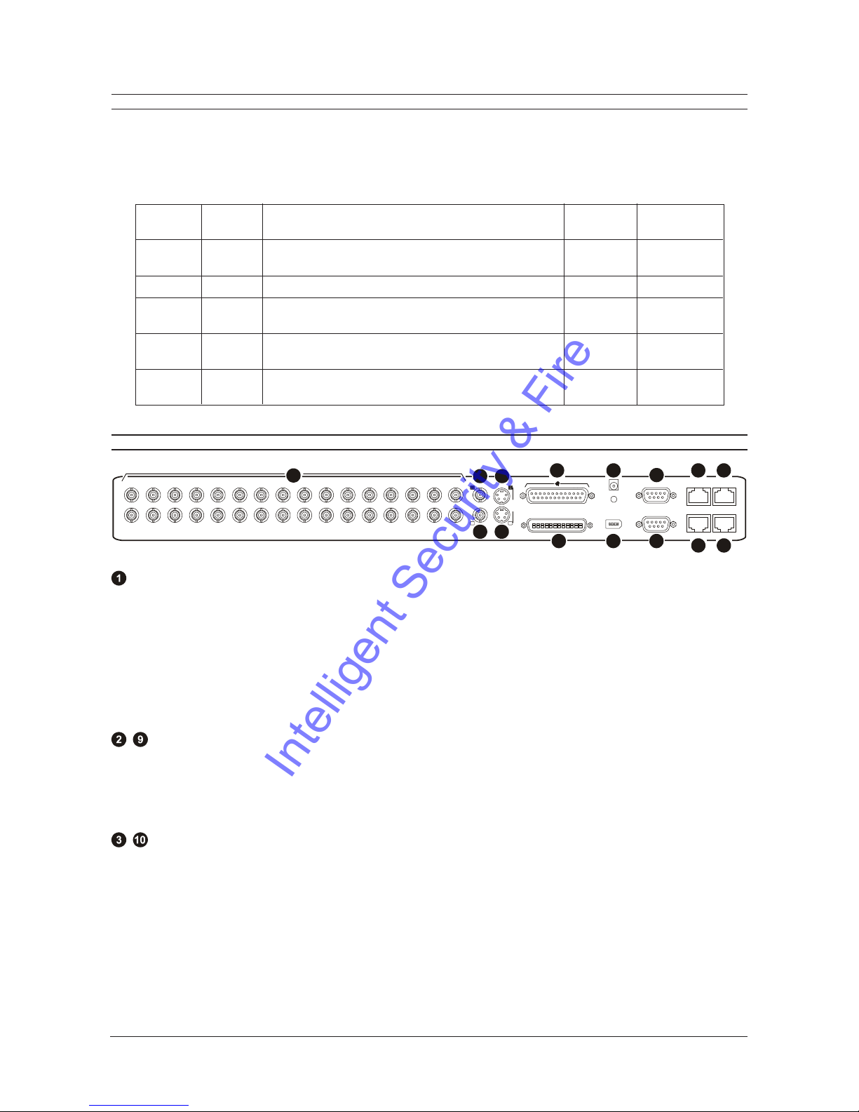
REAR PANEL CONNECTIONS
910 11
1 2 3 4 5 6 7 8 9 10111213141516
AUX
12 VDC
RS232RS232
RS485/1
ETHERNET
10/100
RS485/2 RS232
IEEE 1394
B
S-VHS
SCSI
B
12 13 1414 15
8
6
7
5
4
3
2
1
Camera Inputs
There are two BNC connectors for each camera. Either connector can receive a camera signal. The signal is looped
(directly connected to the other connector), making the camera signal available to other equipment. All connections should
be made using 75-ohm coxial cable with BNC connectors.
The camera input connectors are auto-terminating. This means that the input signal will automatically be terminated with
75-ohms unless a second cable is connected to the second BNC connector of the same camera input. Make sure there is
75-ohm termination at the end of the video line if the signal is looped through the MDR.
Time base correction is performed during digital capture. As a result, cameras do not require synchroni ation.
See page 42 for information about disabling unused camera inputs in the menu system.
, Composite Monitor Outputs A and B
When connecting directly from the MDR to the monitor, select the 75-ohm impedance setting on the monitor.
If an additional device is connected to the monitors looping output, set the termination of the additional device as 75-ohm,
and set the termination of the monitor as Hi-Z (High impedance).
All connections should be made using 75-ohm coxial cable with BNC connectors.
, Y/C Monitor Outputs A and B
The Y/C video outputs have a 4-pin mini-DIN style connector. This style of connection is also referred to as SVHS and S-
Video. All connections should be made using 75-ohm coxial cable.
Pass ord Access Function Changeable Default
Type Level by user? Pass ord
Operator Operator Provides access to the Operator Yes Press ENTER
and System View menus 3 Times]
Installer Installer Provides access to all on-screen menus Yes 3 4 7
Language Installer Provides access to the Onscreen No 1 2 3
Language menu
Factory Installer Resets the multiplexer to factory defaults No 8 1 1
Defaults
Ethernet Installer Deactivates the ethernet password, so that the unit may No 1 1 1
Access be accessed by any PC equipped with WaveReader
IntelligentSecurity&Fire
Page 10
MDR Series Multiplexed Digital Recorders User Manual
REAR PANEL CONNECTIONS
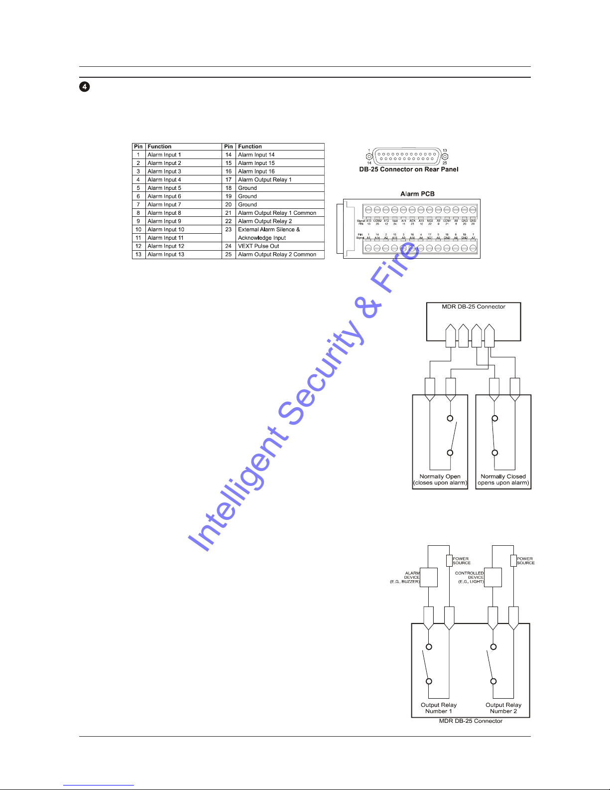
Alarm I/O Port
The back panel of the unit is equipped with an alarm I/O port (DB-25 style connector). Do not attempt to ire directly to
the DB-25 connector on the back panel.
Connect the alarm PCB (supplied with the unit) to the alarm I/O port. Wire all alarm inputs to the alarm PCB as show below:
Alarm Inputs
An alarm condition can be activated by devices such as pressure pads, passive
infrared detectors, door switches, or other similar devices.
Input: 1 per video channel, programmable in the menu system as normally-open
or normally-closed.
High: +5V (+12V maximum)
Lo : 0V
Once connected, alarm inputs can be configured as normally-open or normally-
closed using the menu system. Alarms types should be configured in the menu as
follows:
Normally-Open, Zero Potential Relay Contact: Normally-Open
Normally-Closed, Zero Potential Relay Contact: Normally-Closed
TTL Active High: Normally-Closed
TTL Active Low: Normally-Open
Open Collector Active On: Normally-Open
Open Collector Active Off: Normally-Closed
For more details on alarm configuration, see page 33.
Alarm Relay Outputs
Alarm relay outputs can be activated when an alarm condition exists. The alarm
output is only active for the duration of the alarm.
Output: Zero potential relay contacts programmable in the menu system as
normally-open or normally-closed.
Voltage: 30V maximum
Current: 500mA maximum (short circuit protected)
Alarm relays can be programmed in the menu system to respond to macros and
video loss. See page 36 for more details.
External Alarm Ackno ledge Input
Connect to a switch or similar device to ground this pin in order to acknowledge
an alarm condition, and silence associated bu ers and relays. Connect from pin
23 to either pin 18, 19, or 20 (ground pins).
The contact is a normally-open relay contact.
Pins
2-15 Pin
16 Pins
18-20
Pin
1
Alarm
Input
1
Alarm
Inputs
2-15
Alarm
Input
16 GND
Pin
17 Pin
21 Pin
22 Pin
25
IntelligentSecurity&Fire

Page 11
User Manual MDR Series Multiplexer Digital Recorders
REAR PANEL CONNECTIONS
Po er Input
This 2.1mm barrel, centre positive connector is to be connected to the supplied power supply unit. The unit runs on a 12V
DC, 60 Watt (5 Amp) power supply.
Aux Port
The back panel of the unit is equipped with a aux port (DB-9 style connector). Do not attempt to ire
directly to the DB-9 connector on the back panel.
Connect the supplied audio cable to the aux port. The cable provides five labelled connectors for the
audio input and output, and BNC connectors for monitors C, D, and E:
Audio Output: RCA connector
Audio Input: RCA connector
Composite Monitor C Output: Composite video output with BNC style connector
Composite Monitor D Output: Composite video output with BNC style connector
Composite Monitor E Output: Composite video output with BNC style connector
, RS485 Ports
Two RS485 ports are provided for connecting to keyboards and other RS485 devices. Shields should be grounded at one
end, preferably at the MDR.
See page 48 for information about configuring the RS485 network address settings in the menu system.
1
2
3
4
5
6
7
8
Pin Use
1 Ground (Shield)
2 Not connected
3Network+VE
4 Not connected
5 Not connected
6Network-VE
7 Not connected
8 Not connected
Wire Type 24 AWG, Twisted Pair with
shield (2-wire)
Connector Type RJ-45
Max Cable Length 3200 feet / 1000 metres
10/100 Ethernet Port
The Ethernet port is used to connect live or recorded images to a PC via the Ethernet.
The cable connection configuration depends on the network configuration in use:
For a MDR that connects directly to a hub, use a Straight Through connection.
For a MDR that connects directly to a PC, use a Cross Over connection.
Consult with your Network Administrator for the specific type of configuration. See page 48 for information about configuring
the ethernet settings in the menu system.
1
2
3
4
5
6
7
8
Pin Use
1TX+
2TX-
3RX+
4 Not connected
5 Not connected
6RX-
7 Not connected
8 Not connected
Wire Type Cat 5
Connector Type RJ-45
Max Cable Length 328 feet / 100 metres
Minimum Cable Length 6 feet / 1.8 metres
Hub Wiring Configuration Straight Through
PC Wiring Configuration Cross Over
IntelligentSecurity&Fire

Page 12
MDR Series Multiplexed Digital Recorders User Manual
REAR PANEL CONNECTIONS
SCSI Port
The unit is equipped with a SCSI port for connecting external archive devices. The unit only supports a single SCSI device.
The SCSI ID of the archive device must be set to 0 and the SCSI bus must be terminated, otherwise the system will not
operate correctly.
Additional menu setup may be necessary to configure the archive device. See page 44 for more details.
Connector 50 Pin, High Density SCSI-2
Gender (on unit) Female
Compatible devices MDAe, RAID, DAT, AIT, CD-R, CD-RW
SCSI ID 0
IEEE 1394 Fire ire Port
The unit is equipped with an IEEE 1394 Firewire port for connecting Firewire compatible external archive devices. For
information on the approved devices, please refer to the Archiving Addendum at the back of this manual.
Connector 6 position DIP
Cable 6 position Firewire
Do not connect both SCSI and IEEE 1394 archiving devices to the MDR. Archiving support is only available for
one type of interface at any one time.
DB-9 RS232 Port
A DB-9 RS232 port is provided for modem connection or remote control of unit. See page 47 for information about configuring
the modem settings in the menu system.
Pin Function
1DCD
2RX
3TX
4DTR
5 Ground
6 Notconnected
7RTS
8CTS
9 Notconnected
51
96
RJ-45 RS232 Port
A RJ-45 RS232 port is provided for Event Generation and ASCII Text insertion.
12345678
Pin Use
1 Ground
2 Reserved
3 Not connected
4RXD
5TXD
6 Not connected
7 Ground
8 Reserved
IntelligentSecurity&Fire
Page 13
User Manual MDR Series Multiplexer Digital Recorders
POWERING UP
It is important that power-up procedures are followed carefully. The unit uses an auto-detect feature to detect camera
signals during power-up, and configures itself automatically.
Po er-Up Procedure
Before applying input power to the unit, ensure that all the required connection cables are securely connected. Apply power
to all monitors and cameras, and then apply power to the MDR unit.
Once power is applied to the unit, it will begin the power-up procedure. The unit will begin by displaying the software version
on Monitor A and then the unit will begin recording automatically.
Check Video Input Quality
Check the picture quality by selecting each camera for full screen display. If the picture quality is poor, check the following
items:
The BNC connections
The loop-through terminations
The video levels of incoming signals
The possibility of ground loops
Consult the cameras installation instructions for additional information about proper camera setup.
Check Record And Playback Quality
Record for at least three minutes at the default record rate. Then playback the recording, selecting each camera for full
screen display. Check the playback picture quality.
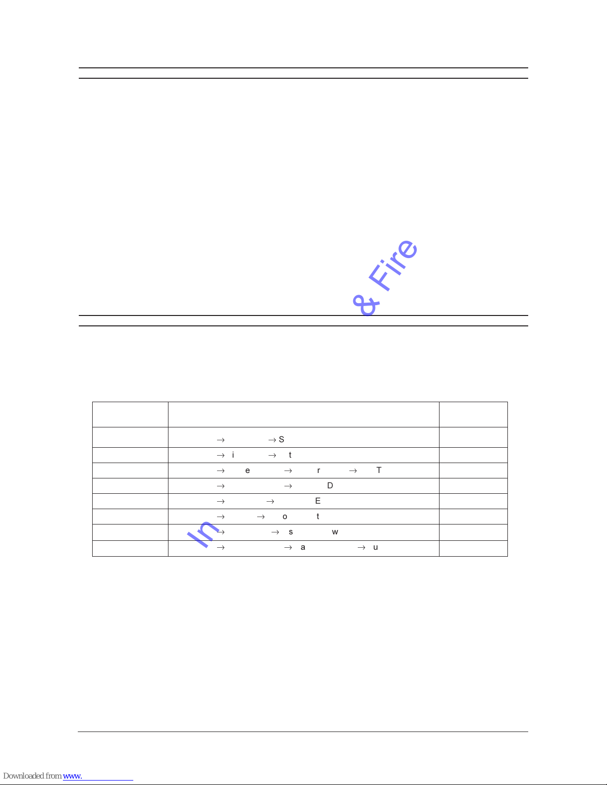
MINIMUM RECOMMENDED MENU SETUP
After installation is complete, it is strongly recommended that, as a minimum, the items in the QuickInstall menu are
configured before the unit is used. All the features located in the QuickInstall menu are also found in the Main menu.
These items are provided in the separate QuickInstall menu as a convenience for the installer.
For information about accessing and configuring the menu system, see page 23.
To find detailed information in this manual about configuring each item in the QuickInstall menu, use the following table to
locate the Main menu location of each item in the QuickInstall menu.
QuickInstall Main Menu Location Page In Manual
Menu Item
Change the Time Main Menu
®
Time/Date
®
Set Time 25
Change the Date Main Menu
®
Time/Date
®
Set Date 25
Edit Camera Titles Main Menu
®
Camera Setup
®
Camera Titles
®
Edit Titles 42
Camera Disable Main Menu
®
Camera Setup
®
Camera Disable 42
Telemetry Enable Main Menu
®ÿ
Telemetry
®
Telemetry Enable 45
Record Quality Main Menu
®
Record
®
Record Quality 29
Installer Password Main Menu
®
Passwords
®
Installer Password 49
Auto Disable Now Main Menu
®
Camera Setup
®
Camera Disable
®ÿ
Auto Disable Now 42
IntelligentSecurity&Fire

Page 14
MDR Series Multiplexed Digital Recorders User Manual
BASIC USER OPERATIONS
IntelligentSecurity&Fire

Page 15
User Manual MDR Series Multiplexer Digital Recorders
THE FRONT PANEL
12
910 11
412 3
16
13 14 15
8
5
6
7
{F}
CDE
B
A
1 2 3 4 5
6
7
8
16 17 18
9
10
19
11 12 13 14 15
Multiscreen Selection Buttons: Select 16, 10, 7, and 4 way multiscreen displays.
Monitor Selection Buttons: Select Monitor A or Monitor B.
Multiscreen Selection Buttons: Select 13, 9, 6 way, and picture-in-picture multiscreen displays.
Monitor Selection Buttons: Select Monitors C, D, or E.
Number Buttons: Select Cameras 1 through 16.
Reverse Play Button: Begin playback in reverse.
Freeze Button: Free e camera images on-screen in Live mode. Pause playback.
Play For ard Button: Begin playback.
Jog/Shuttle: Controls playback speed and menu selections. The Jog is the inner dial and the Shuttle is the outer dial.
Menu Button: Provides access to on-screen menus.
Po er Indicator: Indicates power on/off condition.
Alarm button: Acknowledge and silence alarms.
Sequence Button: Sequence camera views.
Zoom Button: Provides a X2 digital oom.
Function Button: Used in conjunction with the Number buttons to run macros.
Record Button: Start and stop recording.
Stop Button: Stop playback and return to Live mode.
Search Button: Access to stored video data.
Enter Button: Confirm selections in menus.
Important Note: If telemetry is enabled via a remote keyboard, the front panel controls on the MDR are disabled. To re-
establish front panel control, ensure that telemetry is switched off at the remote keyboard.
IntelligentSecurity&Fire

Page 16
MDR Series Multiplexed Digital Recorders User Manual
LIVE VIEWING
The MDR has three principal modes of operationLive Viewing, Playback and Recording. All three of these modes can
operate simultaneously. In Live mode, the following operations are available:
Full Screen Display
Select any camera for full screen display by pressing the Number button of the desired camera. Pressing
the same Number button again displays the Status Display Box. Pressing the same button a third time
displays any associated ATM or cash register ASCII text.
Multiscreen Display
In Live Multiscreen mode, press one of the Multiscreen buttons to activate the multiscreen display on the
currently selected monitor (Monitor A or Monitor B). Live multiscreens are displayed with grey borders. For
detailed information about multiscreen displays, see page 18.
Multiscreen Display With Sequencing
If a multiscreen display does not include all of the cameras, the remaining cameras can be sequenced in
the bottom right cameo. While in a multiscreen display, press the Sequence button to begin sequencing.
For detailed information about sequencing, see page 20.
Sequenced Full Screen Display
While in a full screen display, press the Sequence button to begin full screen sequencing.
The sequence list and dwell times are programmable. For detailed information about programming the
sequence list see page 20.
Zooming
To activate the X2 digital oom, select the full screen display of the camera that is to oom, then press the
Zoom button. Zooming will be indicated by the LED located directly above the Zoom button. Zooming is
also indicated as ZOOM on the primary monitor. Zooming works with fro en and non-fro en images.
Zoomed images can also be fro en. While oomed, rotate the Jog/Shuttle to pan and tilt across the
image. Please note, the camera does not move during digital pan/tilt.
Press the Zoom button again, or another camera button to cancel the oom operations.
Note: If the Zoom button is pressed while in a multiscreen display, the camera from the last active cameo
is selected for full screen display. Press the Zoom button again to activate the oom operation.
Freezing
Pressing the Freeze button free es all camera images on-screen. Full screen free ing is indicated as FRZ
on-screen. Multiscreen free ing is indicated as a flashing asterisk in each fro en cameo. Individual cameos
can be fro en in Active Cameo mode (see page 19). Press the Freeze button again or any Number button
to cancel free e operations.
Selecting Monitor B
To control Monitor B, press the Monitor B button. The Monitor B LED will light to indicate that the number
keypad now controls Monitor B.
Press the Monitor A button again to return the keypad control to Monitor A.
Selecting Monitors C, D and E
To control Monitors C, D or E, press the corresponding Monitor button. The Monitor LED will light to
indicate that the Monitor has been selected.
B
A
C
D
E
1
IntelligentSecurity&Fire

Page 17
User Manual MDR Series Multiplexer Digital Recorders
PLAYBACK
Playback is always displayed on Monitor A. Playback multiscreen borders are black, as opposed to the grey borders of the
live multiscreens. When in Playback mode, Monitor B continues to display full or multiscreen live images.
To begin playback, press the Play For ard or Reverse Play button.
Play For ard
When the Play For ard button is pressed, the unit will play forward at the rate the data was recorded.
While in Playback mode, the user may change the playback direction, playback speed, etc. To return to
Play Forward operations, press the Play For ard button.
Reverse Play
To begin reverse playback, press the Reverse Play button.
Fast For ard and Re ind
During playback, rotate the Shuttle (the outer dial) clockwise to view data at a higher than normal rate.
Rotate the Shuttle anti-clockwise to view data in reverse at a higher than normal rate.
Increasing the amount of rotation increases the rate of playback.
Auto Pause
During playback, moving the Jog (the inner dial) in any direction will free e playback. Depress the Freeze,
Play For ard or Reverse Play buttons to continue playback.
Freeze
During playback, press the Freeze button. This feature pauses all full screen and multiscreen images
Single Frame Advance & Single Frame Re ind
Whilst in Free e or Pause mode, rotate the Jog (the inner dial) to view the frame directly before or after the
frame currently displayed on-screen.
Stop Playback
To stop playback and return to Live Multiscreen mode on Monitor A, press the Stop button.
Multiscreen Display
During playback, press one of the Multiscreen buttons to activate a multiscreen display. The 6-way and
PIP multiscreen displays are not available in Playback mode.
For detailed information about multiscreen displays, see page 18.
Multiscreen Display With Sequencing
If a multiscreen display does not include all of the cameras, the remaining cameras can be sequenced in
the bottom right cameo. While in a multiscreen display, press the Sequence button to begin sequencing.
For detailed information about sequencing, see page 20.
Full Screen Display
Select any camera for full screen display by pressing the Number button of the desired camera. Pressing
the Number button again displays the Status Display Box. Pressing the same button a third time displays
any associated ATM or cash register ASCII text.
Zooming
To activate the X2 digital oom, select the full screen display of the camera that is to oom, then press the
Zoom button. Zooming will be indicated by the LED located directly above the Zoom button. Zooming is
also indicated as ZOOM on the monitor. Zooming works with fro en and non-fro en images. Zoomed
images can also be fro en. While oomed, rotate the Jog/Shuttle to pan and tilt across the image. Please
note, the camera does not move during digital pan/tilt.
Press the Zoom button again, or another camera button to cancel the Zoom operations.
Note: If the Zoom button is pressed while in a multiscreen display, the camera from the last active cameo
is selected for full screen display. Press the Zoom button again to activate the oom operation.
1
IntelligentSecurity&Fire

Page 18
MDR Series Multiplexed Digital Recorders User Manual
PLAYBACK
Searching Recorded Data
The MDR has a powerful search interface feature that allows the user to search for data on the internal hard disk or an
external archive device. The user may search the data for previous recording sessions, text insertion, alarm conditions or
for motion in a selectable area of the scene. Because the search interface is so dynamic, the search interface is covered in
detail in a separate section of this manual. See page 58 for more details.
RECORDING
To begin recording, press the Record button. Recording will be indicated by the LED located directly
above the Record button. The unit always starts recording at the end of previously recorded data. The unit
will continue recording until the Record button is pressed again.
Monitor Displays During Recording
Multiscreen Live and Playback displays on Monitor A and Monitor B are not affected by recording operations.
MONITOR A
MONITOR B
MONITOR C, D, E
LIVE
LIVE
LIVE
LIVE
LIVE
LIVE
LIVE LIVE
LIVE
PLAY
BACK
LIVE
OR
OR
PLAY
BACK
DISPLAY OPTIONS
Available Multiscreen Displays
Use the Multiscreen buttons to activate the multiscreen display on Monitor A or Monitor B. Pressing an individual Multiscreen
button will display the corresponding multiscreen.
6-Way
B
utton
7-Way 9-Way 10-Way 13-Way 16-Way PIP4-Way
D
isplay
The multiscreen display is limited to the number of camera inputs on the unit.
The camera assignments for each multiscreen is retained (in non-volatile memory) for both Live and Playback multiscreen
mode on Monitor A, as well as Live multiscreen mode on Monitors B, C, D and E.
PIP: Use the Jog/Shuttle to adjust the location and si e of the PIP display. Please note that the PIP display is only available
on Monitor A in Live mode when Monitor B is in full screen display mode.
IntelligentSecurity&Fire
Page 19
User Manual MDR Series Multiplexer Digital Recorders
DISPLAY OPTIONS
Displays on MonitorsC through E
These are full screen and analog monitors, displaying only Live images (regardless of the mode selected). A sequenced or
fixed display of any one camera can be selected on MonitorsC through E.
The time, date, alarm, video loss messages, titles and all on screen data on MonitorsC through E are related to
current, live data and must not be confused ith the playback data that might be displayed on MonitorsA or B.
Independent Sequence List and D ell Times
Independent full screen sequences may operate on MonitorsA through E. See page 20 for more details.
Operating on MonitorsC through E
To control Monitors C, D or E, press the corresponding Monitor button. The Monitor LED will light to
indicate that the Monitor has been selected. While the LED remains on, the Number buttons and the
Sequence button operate on the selected monitor, and not on MonitorA.
Selecting a Camera Full Screen on MonitorsA through E
To select a full screen display of an individual camera, select the required monitor (the LED for the selected
monitor will come on) and then press the Number button for the required camera.
Starting Sequencing on MonitorsA through E
To select a sequence, select the required monitor (the LED for the selected monitor will come on) and then
press the Sequence button.
Cancelling Sequencing on MonitorsA through E
To cancel a sequence, select the monitor which the sequence is running on (the LED for the selected
monitor will come on) and then press the Sequence button or a Number button.
ACTIVE CAMEOS
A cameo is defined as any cell within a multiscreen display. Active Cameo mode allows the user to access and edit each
cameo individually.
Entering Active Cameo Mode
While viewing a multiscreen display, enter Active Cameo mode by pressing the Enter button. Active Cameo
mode is indicated on-screen by flashing the number and titles of the active cameo. The LED above the
Enter button is also lit. By default, the top left cameo is activated.
Selecting Cameos
Select a cameo using the Jog/Shuttle to navigate around the multiscreen display. Rotating the Jog selects
the next screen up or down a row. Rotating the Shuttle selects the next screen in numerical order. The
active cameo will always be indicated by the flashing camera number and titles.
Selecting Cameras
Display any camera in the active cameo by pressing the Number button of the desired camera. Once a
camera has been selected, the active cameo advances to the next cameo on the right.
The camera selection only changes the multiscreen currently being displayed. Each multiscreen must be
configured separately. Changes to the multiscreen display are saved in non-volatile memory, and will be
retained even if power is removed from the unit.
Freezing
Press the Freeze button to free e the image in the selected cameo. Each fro en cameo is indicated as a
flashing asterisk on-screen. Press the Freeze button again to cancel free e operations.
C
D
E
1
1
IntelligentSecurity&Fire

Page 20
MDR Series Multiplexed Digital Recorders User Manual
SEQUENCING
The sequencing feature allows a camera to be displayed briefly on-screen, before advancing to the next camera in the
sequence list. The default sequence list displays each camera in numerical order.
D ell Time
The dwell time is the amount of time each camera is displayed on-screen before advancing to the next camera. The Full
Screen and Multiscreen Dwell Times are separately programmable in the menu system.
For detailed information about configuring the dwell times in the menu system, see page 27.
Autolist Custom Sequence List
The Autolist feature allows the user to create a custom sequence list, controlling the order the cameras are displayed and
the dwell time. Separate Autolists may be created for Monitor A (Live and Playback mode) and Monitor B through E (Live
mode). Using a Monitor button, select the monitor to be programmed. Then, using a Number button, select any camera for
full screen display.
Note: The unit must be in full screen display mode before starting to create the sequence list. This initial camera is not part
the sequence list.
To begin recording the Autolist sequence, press the Alarm button and Sequence button simultaneously. Autolist Program
mode is indicated as PGM on-screen. Recording starts when the first Number button is pressed. Press the Number
buttons in the order that the cameras are to appear on-screen. The amount of time between button presses determines the
dwell time. During sequence list programming, pressing any button other than a Number button or the Sequence button
voids the sequence list.
To end the recording, press the Sequence button. The amount of time between pressing the last Number button and the
Sequence button determines the dwell time for the final camera in the sequence list.
Returning To The Default Sequence List
The default sequence list is all cameras in numeric order with a three second dwell time.
To return the unit to the default sequence list, go to the Main Menu
®ÿ
Sequencing
®ÿ
Fullscreen D ell menu. Select 03
seconds by rotating the Jog, then press the Enter button.
Note: Any alteration of the dwell time from this menu will cancel the sequence list and return to the default (numeric) order.
Sequencing In Cameos
While viewing a multiscreen display, additional cameras (cameras not shown in the multiscreen display) can be sequenced
in the lower right hand cameo by pressing the Sequence button. The sequence list is not programmable, but the dwell time
can be adjusted in the menu system. Press the Sequence button again to cancel sequencing.
ON-SCREEN INDICATORS
There are five types of on-screen indicators.
Camera Titles: Displays the camera number and the camera title.
Status Indicators: Displays time, date, and hard disk record time left.
Conditional Indicators: Displays indicators for free e, oom, alarm, motion detection, video loss, Autolist Program
mode, Macro Record and Macro Playback mode.
Status Display Box: Displays archive device, network status and image quality setting (Playback mode only).
Text Display Box: Displays ATM/POS text data.
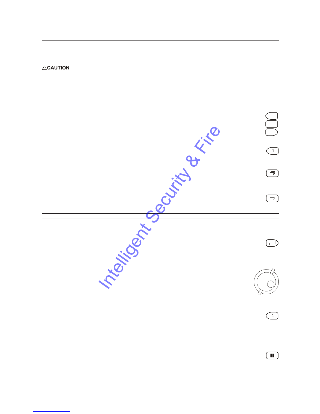
Camera Titles
Camera titles are displayed on either the upper or lower corner of the left hand side of the screen. The camera title can be
changed in the menu system (see page 42).
The user can also change display position and colour. To change the colour and position
of the camera titles, select a camera for full screen display, then press the Enter button to
advance to the next display setting. Repeatedly pressing the Enter button advances the
display settings through the sequence show in the table on the right.
Example: Select Camera 1 for full screen display. Using the Enter button, cycle through
the sequence shown on the right. Each time the position cycle is completed, the unit
advances the Status Indicator colour. Choose Black, White or Grey.
Position Colour
Top Left Black
Top Left White
Top Left Grey
Bottom Left Black
Bottom Left White
Bottom Left Grey
Title not displayed
IntelligentSecurity&Fire
This manual suits for next models
4
Table of contents
Popular Recording Equipment manuals by other brands


Shure
Shure ANI22 manual

DigiDesign
DigiDesign Mbox 2 Setup guide

Northern Airborne Technology
Northern Airborne Technology N301A-000 Installation and operation manual

WisyCom
WisyCom EXP3 installation manual

Agilent Technologies
Agilent Technologies Agilent G1369B user manual

Sound Sculpture
Sound Sculpture MidiUp owner's manual