CHARGESPOT E15 User manual
PRODUCT MANUAL
Last Updated: July 4, 2017

THIS DOCUMENT IS FOR USE ONLY BY ORIGINAL EQUIPMENT MANUFACTURERS (OEMS), OEM
DEALERS OR INSTALLATION SERVICE FIRMS (TOGETHER INSTALLERS) WHO PURCHASE THE
REFERENCED CHARGESPOT COMPONENTS FROM CHARGESPOT WIRELESS POWER INC OR ITS
AFFILIATES (CHARGESPOT).
CHARGESPOT ASSUMES THAT ALL INSTALLERS WHO PURCHASE FROM CHARGESPOT AND WHO
USE THIS DOCUMENT HAVE EXPERTISE IN THE USE OF ELECTRICAL DEVICES AND COMPONENTS,
INCLUDING THE EXPERTISE NECESSARY TO (i) DETERMINE WHETHER OR NOT CHARGESPOT
COMPONENTS ARE SUITABLE FOR USE IN THE SURFACE SUCH COMPONENTS WILL BE INSTALLED
IN, AND (ii) PROPERLY AND SAFELY CONFIGURE AND INSTALL CHARGESPOT COMPONENTS.
ACCORDINGLY, THIS DOCUMENT IS INTENDED ONLY AS A HELPFUL SUPPLEMENT FOR USE BY THE
INSTALLER AND NOT AS A SUBSTITUTE FOR THE INSTALLER’s EXPERTISE. IF ANY INSTALLER USING
THIS DOCUMENT LACKS SUCH EXPERTISE OR DOES NOT AGREE TO THE FOREGOING LIMITED
PURPOSE STATED FOR THIS DOCUMENT, SUCH INSTALLER SHOULD IMMEDIATELY NOTIFY
CHARGESPOT IN WRITING TO THAT EFFECT AND SHOULD NOT USE THIS DOCUMENT.
PRICES AND OTHER TERMS AND CONDITIONS FOR SALE OF CHARGESPOT COMPONENTS TO ANY
INSTALLER ARE GOVERNED BY SEPARATE DOCUMENTS ISSUED OR MADE AVAILABLE TO THE
INSTALLER BY CHARGESPOT, INCLUDING THE INVOICE ISSUED BY CHARGESPOT AND THE
STANDARD TERMS AND CONDITIONS OF SALE LOCATED AT
www.chargespot.com/termsandconditions.html.
IMPORTANT
PURPOSE OF DOCUMENT
CONFIDENTIAL 2/132017 CHARGESPOT WIRELESS POWER INC.

CHARGESPOT EXPECTS THAT THE OEM WILL INCLUDE APPROPRIATE SAFETY WARNINGS AND
INFORMATION FOR END USERS OF ALL OEM PRODUCTS, WHICH INCORPORATE CHARGESPOT
COMPONENTS. SUCH WARNINGS AND INFORMATION MUST INCLUDE THOSE SET FORTH BELOW AND
OTHER WARNINGS AND INFORMATION AS THE OEM DETERMINES NECESSARY AND APPROPRIATE.
DANGER
To reduce the risk of electrical shock:
Always unplug the ChargeSpot from the electrical outlet before removing
Do not reach for a ChargeSpot that has fallen into water – unplug it immediately
Do not disassemble or modify any part of the ChargeSpot
Do not install this product in any electrically conductive surface
WARNING
To reduce the risk of burns, fire, electrical shock, or injury to persons:
This product should not be used by children or persons with disabilities that may hinder their
ability to understand all product information and use the product safely. Close supervision is
necessary when this product is used near children or persons with disabilities
Use this product only for its intended use as described in this manual
Never operate this product if it has a damaged housing, cord or plug cable
Keep cord away from heated surfaces and liquids
Do not operate where aerosol products are being used or oxygen is being administered
This product is designed for indoor use only. Do not install or use this product outdoors
Do not use the ChargeSpot with an extension cord or overloaded electrical outlet
Do not place or leave metallic objects between the charging surface and device being charged
It is recommended that the ChargeSpot be installed to provide 10 cm of separation from persons
IMPORTANT SAFETY INSTRUCTIONS
SAVE THESE INSTRUCTIONS – This manual contains important safety and operating
instructions for ChargeSpot
Before using the inductive charger, read all instructions and cautionary markings on the
inductive charger, power supply, and product using the inductive charger
CAUTION – To reduce risk of injury, charge only Qi-certified or PMA-certified products. Other
types of inductive charging devices may cause personal injury and damage
Install the device minimum 20 centimeters away from the user’s body.
SAFETY INFORMATION
CONFIDENTIAL 3/132017 CHARGESPOT WIRELESS POWER INC.

NOTICE: Changes or Modifications made to this device not expressly approved by ChargeSpot
Wireless Power Inc. may void the U.S. FCC and Canadian authorization to operate this device.
This device complies with part 15 of the FCC Rules. Operation is subject to the following two
conditions:
(1) This device may not cause harmful interference, and
(2) this device must accept any interference received, including interference that may cause
undesired operation.
NOTE: This equipment has been tested and found to comply with the limits for a Class B digital
device, pursuant to part 15 of the FCC Rules. These limits are designed to provide reasonable
protection against harmful interference in a residential installation. This equipment generates, uses
and can radiate radio frequency energy and, if not installed and used in accordance with the
instructions, may cause harmful interference to radio communications. However, there is no
guarantee that interference will not occur in a particular installation. If this equipment does cause
harmful interference to radio or television reception, which can be determined by turning the
equipment o and on, the user is encouraged to try to correct the interference by one or more of
the following measures:
Reorient or relocate the receiving antenna.
Increase the separation between the equipment and receiver.
Connect the equipment into an outlet on a circuit dierent from that to which the receiver is
connected.
Consult the dealer or an experienced radio/TV technician for help.
This device complies with Industry Canada’s licence-exempt RSSs. Operation is subject to the
following two conditions:
(1) This device may not cause interference; and
(2) This device must accept any interference, including interference that may cause undesired
operation of the device.
This equipment complies with Industry Canada RF exposure limits set forth for an uncontrolled
environment. The device and its antenna must not be co-located or operating in conjunction with
any other antenna or transmitter. This equipment complies with FCC RF exposure limits set forth
for an uncontrolled environment. The device and its antenna must not be co-located or operating
in conjunction with any other antenna or transmitter. The equipment should be installed and
operated with minimum distance 20 cm between the the transmitter and your body.
FCC & INDUSTRY
CANADA COMPLIANCE
CONFIDENTIAL 4/132017 CHARGESPOT WIRELESS POWER INC.

Safety is dependent on the proper installation and servicing of the ChargeSpot. It is important to
read and follow all instructions before installing this product. To properly install a ChargeSpot you
must have a good understanding of electrical procedures and systems, along with proficiency in
the installation and service of oice, commercial and residential work surfaces. There are no
adjustments required at any time to the electrical components within the charging mount. OEMs
and installers should not open the ChargeSpot housings or make modifications to the ChargeSpot
or components unless expressly approved in writing by an authorized representative of
ChargeSpot Wireless Power Inc. Any changes or modifications will void the product warranty.
DURING INSTALLATION
DO NOT connect the ChargeSpot to an electrical outlet until:
ALL other electrical connections are made
Mounting of ALL components is complete
VERIFICATION that no short circuit exists in the entire system
DO NOT install equipment or route wiring cords in the path of any walkways or moving
components
When drilling into the work surface, DO make sure that both sides of the surface are clear of
anything that could be damaged
AFTER INSTALLATION
Test the installed ChargeSpot to ensure that it is working properly
File these instructions in a safe place and refer to them when performing maintenance or
re-installing
WARNING: Failure to follow all safety precautions and instructions may result in death, serious
injury, or property damage. The OEM assumes sole responsibility for such precautions and instruc-
tions and for any failure to follow them.
DISCLAIMER
By proceeding with the installation of ChargeSpot components in OEM products, the OEM agrees
that: (i) CHARGESPOT is not liable under any theory of contract, tort law, or otherwise for any loss,
damage, death, personal injury, special, incidental, or consequential damages, or any other
damage of any nature arising directly or indirectly from or relating to the improper installation or
use of CHARGESPOT products or components in residential or oice furniture or any other
application; and (ii) the OEM will defend, indemnify, protect, and hold harmless CHARGESPOT and
each of its ailiates, oicers, directors, agents, and employees from and against any such liability,
SAFETY CONSIDERATION
FOR INSTALLERS
CONFIDENTIAL 5/132017 CHARGESPOT WIRELESS POWER INC.

claims, injuries, losses, and damages. In order to safely install and use CHARGESPOT products and
components, full consideration of the work environment (e.g., location of electrical wiring, support
members, surface thicknesses, and other electrical and structural components) is required.
CHARGESPOT disclaims responsibility for improper use or installation of products or components
and use or installation not consistent with the original manufacturer specifications and recommen-
dations (if any) for such products or components.
WARRANTY INFORMATION
Neither this document nor the statements in this document create any warranties, express or
implied, regarding ChargeSpot components. All information regarding any warranties made by
CHARGESPOT to the OEM purchaser of ChargeSpot components is located in separate documenta-
tion provided by CHARGESPOT to the OEM. CHARGESPOT makes no other warranties and specifi-
cally disclaims any express or implied warranties of merchantability or fitness for purpose. No
warranty shall extend to any person other than the OEM who purchases the ChargeSpot compo-
nent from CHARGESPOT.
CONFIDENTIAL 6/132017 CHARGESPOT WIRELESS POWER INC.

The OEM is solely responsible for taking all steps necessary and appropriate for safe and proper
installation of ChargeSpot components. These steps include, without limitation, the following:
INSTRUCTIONS & PERSONNEL
The OEM should use only properly trained and qualified personnel for installation. The OEM
should assure that all such personnel read and fully understand this document prior to
beginning installation.
CONDUCT A “BENCH TEST”
The OEM should conduct a “bench test” to verify that all electronic issues are resolved prior to
installation:
Make sure the ChargeSpot is operational with a Qi-certified or PMA-certified receiver device
before being installed
Check the Power Supply connection for proper fit
PRE-INSTALLATION
CONSIDERATION
CONFIDENTIAL 7/132017 CHARGESPOT WIRELESS POWER INC.
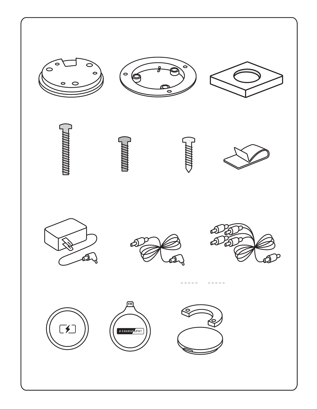
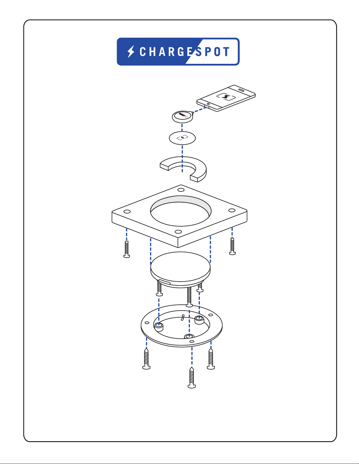
1x ChargeSpot 1x Mounting Plate
3x
3/4”– #8-32
Machine Screws
3x
1/2”– #8-32
Machine Screws
3x
Wire Clips
3x
1/2”– #6
Wood Screws
2x Stickers/De-
cals
Sparks
Apple Lightning
& mUSB
CHARGESPOT INSTALLATION KIT
Power Adaptor 15 Multi-Unit
Power Supply
5 Single-Unit
Power Supply
1x ChargeSpot Jig
CONFIDENTIAL 8/13
Decal
Placement Tool
(2 pieces)
or
2017 CHARGESPOT WIRELESS POWER INC.
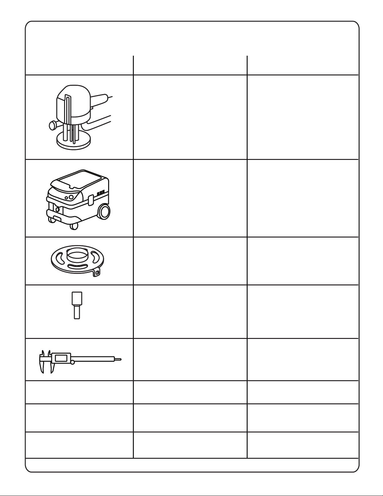
TOOLING LIST
NAME DESCRIPTIONTOOL
Festool 574342 OF 1400 EQ Plunge
Router
Festool 583492 CT 26 HEPA Dust
Extractor
Includes: Chip Catcher, Collets (¼”,
½”, & 8mm), Dust Extraction Hood,
Guide Rods (pair), Plug-It Power
Cord, and Standard US Guide
Bushing Adapter.
Ships in: Systainer 4 Case.
Also provided: Printed
Supplemental Manual.
Includes: 27mm Anti-static Hose,
Cord Wrap, Filter Bag, HEPA Filter,
and Hose Garage.
Festool 492183 Template Guide,
24mm OD / 21mm ID
Copy ring for use with OF 1400
Router.
Whiteside 1086 Router Bit Straight
¾”X1-½”
Diameter: ¾”.
Cutting Length: 1-½”.
Overall Length: 3”.
Shank: ½”.
Two-Flute.
Wixey WR100 Digital Fractional
Caliper
Includes: Battery, Case.
Measuring Length: 6”.
Increments: 1/64”.
Provided by ChargeSpot
Provided by ChargeSpot
Router jig
ChargeSpot Decal
Placement Tool
Provided by ChargeSpot
ChargeSpot Test
Receiver
CONFIDENTIAL 9/13
For tooling overviews and set-up please see https://chargespot.wistia.com/projects/sg6zfb9w1v
2017 CHARGESPOT WIRELESS POWER INC.

MACHINE SCREW LENGTH
Substrate thickness aects the device ONLY in screw length.
Refer to Table 1 for the resulting screw length requirements and proper mounting position (Figure A).
Table 1: Screw Length Selection Based on Substrate Thickness
Figure A. ChargeSpot placed in mounting plate
CONFIDENTIAL 10/132017 CHARGESPOT WIRELESS POWER INC.
8-32 x ½" ( 3 provided )
8-32 x ¾" ( 3 provided )
8-32 x1" ( not included )
8-32 x 1¼" ( not included )
8-32 x1 ½ " ( not included )
MACHINE SCREW
LENGTH
SUBSTRATE
THICKNESS
18 - 24mm ( 0.71" - 0.95" )
24 - 31mm ( 0.95" - 1.2" )
31 - 37mm ( 1.2" - 1.45" )
37 - 44mm( 1.45" - 1.7" )
44 - 51mm ( 1.7" - 2" )

xy
xy
at least 2”
clearance around
SAFETY
Please read all safety instructions before installation.
DURING INSTALLATION
DO NOT connect the ChargeSpot to an electrical
outlet until:
ALL other electrical connections are made
Mounting of ALL components is complete
VERIFICATION that no short circuit exists in the
entire system
DO NOT install equipment or route wiring cords in
the path of any walkways or moving components.
When drilling into the work surface, DO make sure
that both sides of the surface are clear of anything
that could be damaged.
AFTER INSTALLATION
Test the installed ChargeSpot to ensure that it is
working properly.
File these instructions in a safe place and refer to
them when performing maintenance or re-installing.
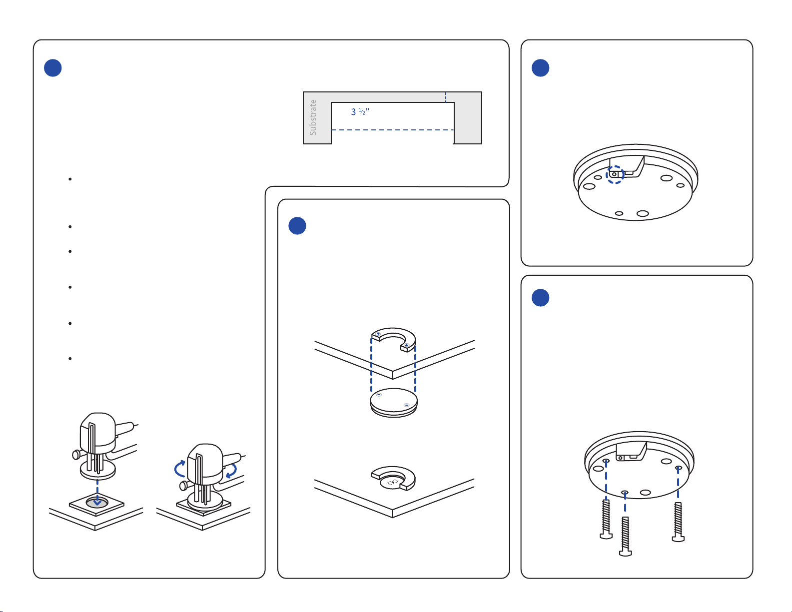
PREPARE
ChargeSpot will ship Product Kit with all necessary
materials.
Please refer to
https://chargespot.wistia.com/projects/sg6zfb9w1v
for video tutorials and tool set up.
Mark the center for each ChargeSpot location
on the underside of the surface (Figure 1).
Find approximate location on the topside of
the surface to ensure correct position.
(For retrofit only) Ensure adequate working
space available for router before cutting
(e.g., cutting the holes requires additional
space for the router to move).
1
INSTALLATION INSTRUCTIONS
LOCATE
Figure 1a. underside of table
Figure 1b. topside of table
2MEASURE
Using the digital caliper, measure the thickness
of the table and jig together (Figure 2a).
Figure 2a. Measure the table and jig thickness together.
CALIPER ROUTER
NOT
JIG
¼” (6mm)
Figure 2b. Use the end of the caliper and the router
bit to ensure proper measurement before cutting.
CALIPER ROUTER
¼” (6mm)
JIG
Desired depth of the hole to be cut is 6mm from
the surface. IMPORTANT: Check for correct
measurements before cutting (Figure 2b).
2017 CHARGESPOT WIRELESS POWER INC. CONFIDENTIAL 11/13
First connect the power supply to the
ChargeSpot before mounting (Figure 5).
Plug the power supply into an outlet to test
the unit.
5POWER SUPPLY
Attach the jig to the desired location with
provided screws. A recessed hole that is 3½”
in diameter will need to be routed from the
underside of the substrate to within 6.0mm
from the surface (1/4”) from the surface
(Figure 3a, 3b).
IMPORTANT: The depth of the hole must be
precise in order for optimal
performance of the ChargeSpot (Figure 2b).
Remove table surface if possible
Ensure ChargeSpot unit fits into each hole
and sits flush in the recessed hole
Test ChargeSpot unit to ensure remaining
surface thickness is to specification
Take caution not to penetrate the surface
when boring the recessed pocket
The type of substrate the ChargeSpot is
mounted into DOES NOT aect the
installation of the device.
3CUT
Diameter
Recessed Pocket
Figure 3a. Move the router clockwise
while routing
Aer cutting the pocket from the underside
use the ChargeSpot decal placement tool
(Figure 4) to accurately locate and place the
table decal on the topside before mounting.
4DECAL PLACEMENT
Figure 3b. The recessed hole must be 6mm from
the surface
Figure 4a. Decal placement tool (two pieces) are
magnetized
Figure 4b. Use the tool as a guide to place the decal
Figure 5. Power supply jack on the ChargeSpot
Determine appropriate machine screw
length using attached chart (Page 10).
Attach the three (3) appropriate machine
screws to the bottom of the ChargeSpot as
demonstrated in Figure 6a below. Ensure
that the screws are not tightly fastened to
leave room for depth adjustment.
6MOUNTING
Figure 6a
2017 CHARGESPOT WIRELESS POWER INC. CONFIDENTIAL 12/13
¼” (6mm)

With the three (3) machine screws attached,
place the ChargeSpot on top of the mount-
ing plate. Ensure the screws attached to the
charger are aligned with the corresponding
counter bores on the mounting plate
(Figure 6b). The resulting assembly should
appear as in Figure 6c.
6MOUNTING (continued)
Figure 6b. The screw heads of the ChargeSpot should be
placed in the holes of the mounting plate.
Figure 6c. ChargeSpot with mounting plate
Figure 6d. ChargeSpot placement in recessed hole
From the underside of the substrate, place
the ChargeSpot with the attached mounting
plate into the recessed hole (Figure 6d).
The ChargeSpot requires three (3) no.6 x ½”
Phillips round-head wood screws to be
installed into the mounting plate to hold the
charger in place (see dashed circles in Figure
6e). The OEM should ensure that the no.6 x ½”
Phillips screws do not penetrate the substrate
surface. This completes the steps necessary to
mount the ChargeSpot.
Figure 6e. Secure mounting plate against
surface underside
If the ChargeSpot transmitter is not flush
against the under of the substrate, use a Philips
head screwdriver to loosen the corresponding
machine screws until flush. Note that the
transmitter must sit flush against the underside
of the substrate to operate properly.
Consideration and implementation of cord
management should be used when
installing the power supply.
Zip ties can be applied at three (3) points on
the mounting plate to tether excess cable to
the device (arrows in Figure 6e).
Provided wire clips should be used to
properly mount wires.
The ChargeSpot should be positioned on the
work surface where the provided power supply
can reach an electrical outlet without interfer-
ing with walkways or moving components. The
ChargeSpot should not be installed in any
electrically conductive work surface.
Confirm that ChargeSpot unit can transfer
power to the Test Receiver through the surface
IMPORTANT: The recessed hole must be
within 6mm or 1/4” of the surface and the
decal must be accurately placed otherwise the
Test Receiver LED will fail to light consistently
Place the Test Receiver over the decal on
the surface
The Test Receiver test unit LED should light
up within 1 second
Remove the Test Receiver for 3 seconds
Repeat previous 2 steps two more times to
ensure consistency
TIP: During testing, always reset positioning
by picking up and placing the Test Receiver
down; ‘nudging’ will not reset the Test
Receiver properly
7TESTING
Figure 7. Place the Spark on the decal
CONGRATULATIONS ON
INSTALLING CHARGESPOT.
START CHARGING!
2017 CHARGESPOT WIRELESS POWER INC. CONFIDENTIAL 13/13
¼” (6mm)
Table of contents


