Etrel INCH DUO User manual

Document version: 1.4
Document date: 11. 11. 2021

Etrel INCH DUO | Electrical Installation Specifics
Technical
|
TABLE OF CONTENTS
1BASIC DESCRIPTION ....................................................................1
About this Document.........................................................................1
Site Preparation .................................................................................1
Permits...............................................................................................2
Location..............................................................................................3
Required Space ..............................................................................4
Charging Station Dimensions.........................................................4
Content, Optional and Extra Equipment............................................5
Tools...................................................................................................6
2PRODUCT DESCRIPTION ..............................................................7
Components Overview ......................................................................8
Base Specifications.............................................................................8
Grid Connection.................................................................................9
Connection to the Station Operator's Communication Network..9
Circuit Diagram ................................................................................11
External Signal..................................................................................12
Digital Inputs and Digital Outputs................................................12
3CABLE CROSS-SECTION SELECTION.............................................13
Minimum Cables Cross-Section .......................................................13
Other Consumption or Production of Electricity at the Location....17
4DIMENSIONING OF A CLUSTER ..................................................19
Cabling Route for the Connection of Multiple Charging Stations....20
Cluster Cables Cross-Section............................................................22
Examples of Connection ..............................................................28
5CONNECTING CHARGING STATION ............................................34
Insertion of Cables Through the Installation Pipe ...........................34
Preparation of Cables ......................................................................35
Power Supply Compartment............................................................35
Connection of the Protective Earthing (PE).................................38
Connection of the Power Cable...................................................39
Connection of the Communication Cable (UTP)..........................39
Finishing Work .................................................................................40
6ELECTRICAL MEASUREMENTS....................................................42
Earthing Conductor Continuity test.................................................42
Insulation Resistance Measurement ...............................................43
RCD Test...........................................................................................44
Effectiveness of the Protection Against Electric Shock....................45
Earth Electrode Resistance Measurement ......................................46
7OPERATION AND CHARGING PROCEDURE..................................50
First Power up..................................................................................50
First Charging Session ......................................................................51
8CONTACT INFORMATION ..........................................................57

1 | 57
Etrel INCH DUO | Electrical Installation Specifics
Technical
|
1 BASIC DESCRIPTION
ABOUT THIS DOCUMENT
The safety and installation instructions "Quick Start Guide" that comes
with the charging station should be read first and can also help with the
installation procedure:
•Etrel_INCH_DUO_QuickStartGuide.pdf
•Etrel_INCH_DUO_QuickStartGuide_Figures.pdf
The document in front of you contains information on the specifics of
electrical installation of the INCH DUO charging station. As it is necessary
to consider the physical installation, basic information about it is also
included.
More information about physical installation is available in the document
“Physical Installation”:
•Etrel_INCH_DUO_Physical_Installation.pdf
All the documents are available in the installation manuals section,
accessible from the INCH DUO product page, at the web page
https://etrel.com/charging-solutions/inch-duo/
SITE PREPARATION
CONFIRMATION OF READINESS
Before carrying out the installation, the client must confirm his readiness
usually with a statement, that all the requirements for the preparation of
the location and additional image material are met, which allows remote
checking of compliance.
ACCESS TO INSTALLATION SITE
An access to the location should be made possible to service vehicle for
installation and servicing of charging stations.
SUPPORT DURING INSTALLATION
The responsible staff for both electricity installations and IT
communications should be present on the location or available for
immediate remote support.

2 | 57
Etrel INCH DUO | Electrical Installation Specifics
Technical
|
EXTERNAL FACTORS
Installation cannot be carried out in the event of extremely rainy or snowy
weather or other external factors that can prevent safe mounting,
installation, and commissioning of charging stations. The charging station
installation should be cancelled under such circumstances.
INSTRUCTIONS VALIDITY
The client shall check with manufacturer for the latest valid version of
instructions before the preparation of location(s) for installation of
charging stations. Please make an inquiry with the point of contact at the
retailer or manufacturer’s support of your charging station to request the
latest instructions version when necessary.
PERMITS
LOCATION AND BUILDING PERMIT
The charging station is a simple object and there is usually no need to
acquire any building permits for its installation. If the installation site is a
part of municipal property, consent of the relevant authorities must be
acquired before the charging station can be installed. Installations must
be performed in accordance with possible additional requirements of the
national regulation.
CONNECTION TO THE GRID
The charging station must be connected to the low-voltage electricity
distribution network. No special permit is required to connect to an
existing network behind the metering point. The connection can be done
by any authorised electrician. Installations must be performed in
accordance with possible additional requirements of the national
regulation.
PARKING PERMITS
Parking must be possible in the direct vicinity of the station and permitted
by the operator or owner of the parking area. Estimated time for a full
charge depends on the current state of the battery and the vehicle's
charging power. Charging procedure usually takes between 30 minutes
and up to 8 hours. Installations must be performed in accordance with
possible additional requirements of the national regulation.

3 | 57
Etrel INCH DUO | Electrical Installation Specifics
Technical
|
LOCATION
Charging station should be installed in the vicinity of the parking spot that
will be used to park and charge electric vehicles. They can have charging
socket located in various positions. Consequently, cable length to connect
EV and charging station is important.
The sufficient cable length to easily connect the electric vehicle with the
charging station, regardless of where the EV’s charging socket is located,
should be between 3 and 7 m and depends on the charging station
location in comparison to parking spot. Shorter length cables are
recommended as they are easier to handle.
Make sure that in a typical connection scenario there are no obstructions
in the way of the charging cable. When in use, the charging cable should
be laid so that it will not be stepped on, tripped over, or otherwise
subjected to damage or stress.
Charging station should be mounted so that the plug of the charging
station is located approximately 120 cm above the ground. This height
enables averagely high user the easiest operation of charging station and
connection of charging cable. It also provides best view and operation of
the LCD screen.
Etrel INCH charging station and its components (cable, casing, LCD
screen...) are developed to be installed in the outside area meaning that
charging station is resilient to the external actors (UV rays, rain, snow,
cold etc.). Installing it in the closed-up area, for example in garage, will
prolong the lifespan of the charging station and keep it in a pristine
condition for longer.
THERE IS NO FUNCTION OF VENTILATION IMPLEMENTED IN THE
CHARGING STATION.
Location of the charging station must meet the following criteria:
•The charging station must not be submersed in water or any other
fluid and should not be installed in flood risk areas.
•The operational temperature of the charging station is between
- 25°C and + 65°C.
For locations where the charging station will be exposed to direct
sunlight and high ambient temperatures during the day, it is
recommended to install protection from direct sunlight,
otherwise the temperature inside the station may exceed 65°C.
•Charging station must not be installed in explosion hazardous
areas (EX zone)

4 | 57
Etrel INCH DUO | Electrical Installation Specifics
Technical
|
REQUIRED SPACE
Basic installation of the charging station without arches requires an
excavation of minimal dimensions of 550 mm x 420 mm (floor plan) and
depth of 600 mm. If the charging station is installed together with two
safety arches, dimensions of the required dimensions are approximately
800 mm x 550 mm. Please find more information in chapter Construction
Works.
CHARGING STATION DIMENSIONS
Figure 1: INCH DUO dimensions
Additional considerations of dimensions:
•The height of the charging station is 1343 mm.
•Basic dimensions of the station's base: 272 mm x 200 mm.
•Free space needed:
o50 mm in the back.
o150 mm on the left and right side.
o500 mm at the front (140 mm for opening the station doors
and additional space to enable simple maintenance).
5 | 57
Etrel INCH DUO | Electrical Installation Specifics
Technical
|
Two air vents are built into the station, one on the top of the back side
and another in the middle of the back side. Air vents must not be blocked
or obstructed by other items or objects. When applicable, air vents must
be protected from being covered with snow.
The charging station is equipped with standard sockets (Type 2 according
to EN 61851 or EN 62196-2). Charging cables are not a part of the station's
equipment. It is expected that the users carry charging cables in their
vehicles. EV parking places must be placed within the reach of the
charging cable. Minimum length of the charging cable should be 2.5 m (in
the case of the most optimal EV parking to charge on both sockets).
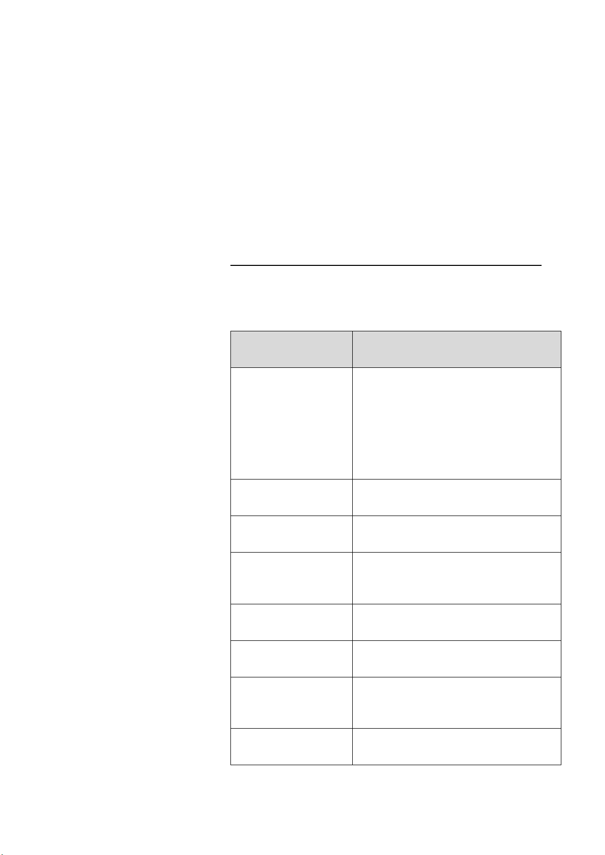
CONTENT, OPTIONAL AND EXTRA EQUIPMENT
The table below shows the optional and extra equipment that can be
added to the charging station:
Optional / Extra
equipment
Use/Description
GPRS router with
network switch
GPRS router can be used for communication
for several chargers on the same location
(required for control centre connection
when local connection via Ethernet is not
possible). Network switch can be used to
connect several stations on the same
location with one router.
Safety arches
(Protective railing)
Protects the station from vehicle collisions.
Underground anchoring
structure
For safe installation of charging station and
safety arches.
Different graphical user
interface languages
Based on user identification, the station can
automatically adjust the language of the
user interface.
Visual customisation of
the station
Custom labels with client’s design,
logotypes, or promotions.
Connection of two sets
of supply wires
Special connection terminals can be used to
connect several stations in a row.
Etrel Load Guard
Enables management of charging current
based on settings in the control centre for
management of charging infrastructure.
Etrel Ocean
Control centre for management of charging
infrastructure.
6 | 57
Etrel INCH DUO | Electrical Installation Specifics
Technical
|
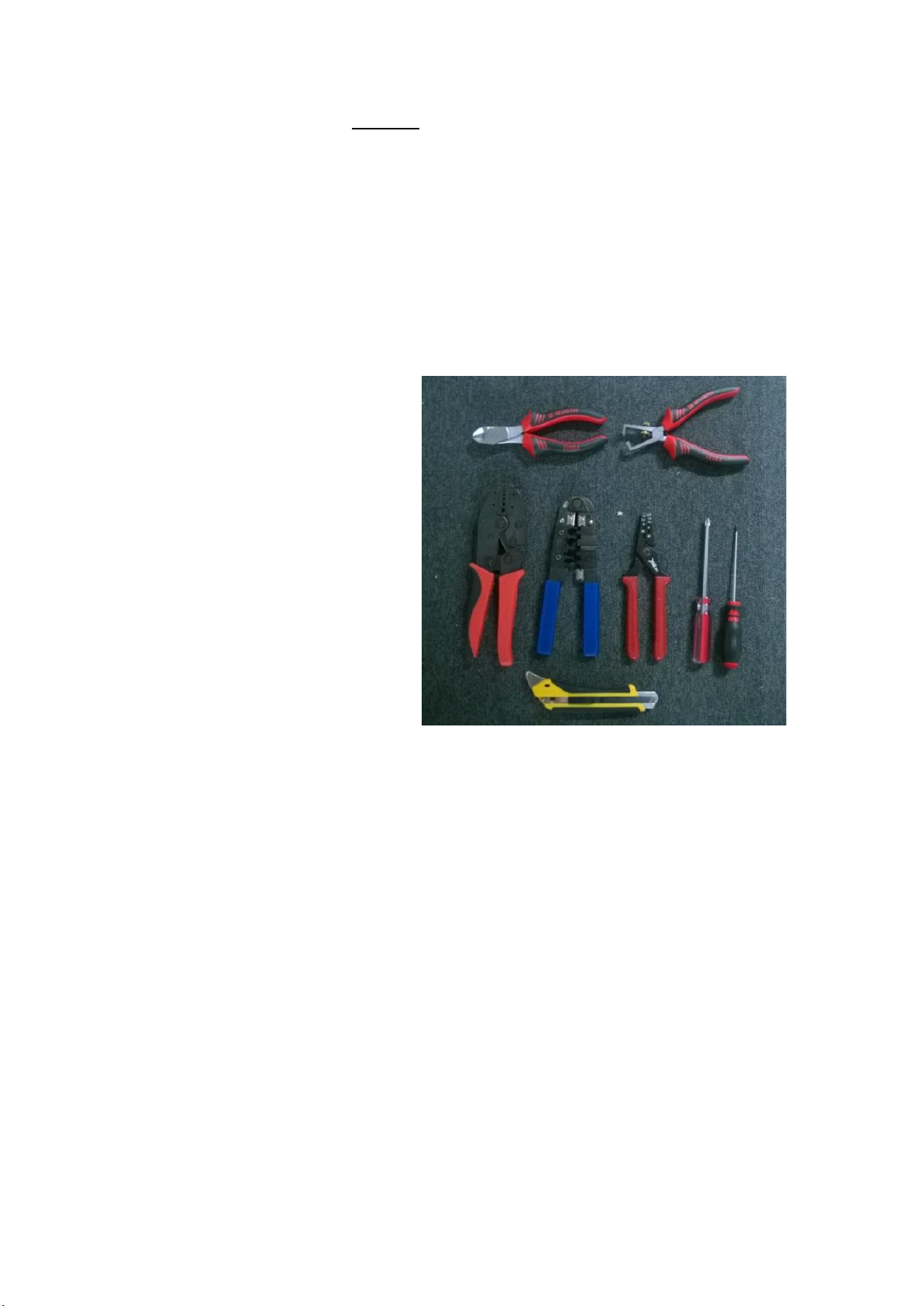
TOOLS
To execute the installation of charging station multiple tools are needed:
•Screwdriver,
•Hex screwdriver (if charging station without key lock on
maintenance doors),
•Utility knife,
•Self-adjusting crimping pliers for cables' end sleeves,
•Wire trippers and
•Cable rippers.
Figure 2: Equipment used for the installation of charging station

7 | 57
Etrel INCH DUO | Electrical Installation Specifics
Technical
|
2 PRODUCT DESCRIPTION
The Etrel’s public charging station INCH DUO is highly configurable and
can be tailored to the client’s specific needs. It allows simultaneous
charging of two vehicles with power of up to 2 x 22,08 kW and is equipped
with standard Type 2 sockets (EN 61851 or EN 62196-2).
The actual number of maximal charging power can differentiate the exact
value for one charging spot considering voltage of 230 V is 22,08 kW.
Charging is limited to 32 A, however voltage specified as 230 V, can be
between 207 V and 253 V (+- 10 %). This means that the actual charging
power can be lower or higher of the specified 22,08 kW.
Another factor heavily influencing what is the charging power is the power
factor (cos Fi), which is determined by the internal charger in the electric
vehicle. This factor is always lower than one, meaning that all power is not
active, there is also reactive component. The correct designation of
charging power would therefore be 2 x 22,08 kVA (or 44,16 kVA).
No matter the specifics, the charging power of Mode 3 charging spot is
commonly referenced as 22 kW (or 44 kW for charging station with two
charging spots). This simplification is used in this document as well.
Charging station comes with the LCD screen that guides through the
charging process and provides important charging information. Charging
station comes with several connectivity options (including LTE and
Ethernet) and open protocol support and can be seamlessly integrated in
the smart home system.
Certified utility-grade meters as well as all optional utility feeder
equipment are embedded in the station. The station can be equipped
with an RFID identification module, which prevents unauthorized use and
is necessary to enable different billing and reservation processes and
other advanced functionalities. The station also supports remote
identification with SMS or other external identification means.
The casing of the charging station is robust enough to withstand any
unfavourable weather conditions and potential damage which may occur
in open public areas. The compact dimensions of the charging station
allow its installation in a small area, for example close to the edge of the
pavement or roadside curb.
Modular design allows simple replacement of key components that can
become damaged due to wear and tear or vandalism (especially the
charging sockets). The station's service doors use a special three-point
locking mechanism. The doors open outwards and to the side to simplify
the work of maintenance staff.

8 | 57
Etrel INCH DUO | Electrical Installation Specifics
Technical
|
COMPONENTS OVERVIEW
The Etrel INCH DUO public charging station contains the following
components:
•Casing of the station,
•two charging spots (Type 2 sockets, single- or three-phase),
•main controller of the station,
•LCD display that guides user through the charging process,
•user identification module with RFID card reader,
•ethernet communication connection point,
•built-in smart energy meters for each charging spot,
•electrical protection of each socket,
•three-phase grid connection point equipped with standard safety
protection.
1
Figure 3: Arrangement of equipment inside the station
BASE SPECIFICATIONS
•Input: 2x230/400V~; 3W+N+PE; 50/60 Hz; 32 A max.
•Output: 2x230/400V~; 3W+N+PE; 50/60 Hz; 32 A max.
•Maximum charging power: 2 x 22 kW (3-phase)
•Device power consumption:
oFrom 5 W, depending on the actual configuration.
1) Grid connection of the charging
station, which contains terminals for
all supply wires (L1, L2, L3, N and
PE).
2) Energy meters for each socket. For
normal functioning of the station, a
working communication connection
between the main station controller
and the energy meters is required.
3) Differential and overcurrent
protection of each socket.
4) Module for communication with
electric vehicle (compliant with the
IEC 61851 standard), socket voltage
monitoring components, socket
contactors.
5) Main station controller with RFID
reader, RFID antenna and LCD
display, control circuit power supply,
and communication modules
(Ethernet or GPRS router).

9 | 57
Etrel INCH DUO | Electrical Installation Specifics
Technical
|
GRID CONNECTION
The charging station can be connected directly to the electricity
distribution network or to an existing electrical installation nearby. Supply
power depends on the charging power of each socket (according to the
configuration of the charging station).
The following supply power is required:
•44 kW (64 A): 2 x three-phase charging spots, for each Type 2
socket is the maximum current 32 A per phase.
Supply power of the charging station must be dimensioned appropriately
to enable simultaneous charging of two vehicles.
Charging power of each charging spot can be limited in the settings of the
charging station on the scale between 6 A and 32 A. The charging station
can also be set up to allow local power management so that when two
vehicles are connected at the same time, the available maximum power
is divided between the two vehicles. Power management can also be
setup for a cluster of charging stations.
In the execution phase of the grid connection project, the following
requirements need to be met:
•Selectivity of the functioning of protection devices needs to be
ensured:
oThe main overcurrent protection should be at least one class
greater than the one used for the protection of the charging
station or have a higher delay.
oDifferential protection (RCD) which is used in the charging
station operates at a low current (ΔI 30 mA, without delay).
The selectivity of this protection on the level of facility is
achieved with a higher delay or a greater current differential.
•Five wires are routed to the station, including three phase wires,
grounding wire, and the neutral wire (when connecting to an
existing installation). For single phase connection (slow charging
option), only one phase wire with sufficient diameter can be
routed to the station, together with neutral and earthing
conductor. Dimensioning of the wires is determined in the project
documentation. Grounding wire must be connected to the main
grounding busbar.
CONNECTION TO THE STATION OPERATOR'S
COMMUNICATION NETWORK
The charging station uses network connection to communicate with the
Control centre to cyclically send information about its status, perform

10 | 57
Etrel INCH DUO | Electrical Installation Specifics
Technical
|
identification of users (on the Control centre level), forward events that
occur during its operation and execute billing for the services performed.
The connection also enables communication from the Control centre
towards the charging station, which enables remote access to the station
for needs of maintenance or remote control.
The charging station could require a connection to the station operator's
WAN network (charging infrastructure control centre). To access the WAN
network via an internet connection, some additional security
requirements need to be observed.
Network connection can be executed in several different ways:
•Direct connection to the station operator's WAN network.
Connection can be established directly with a UTP cable or a fibre
optic converter.
•Wireless connection. The station connects to an existing LTE
2G/3G/4G mobile network with an GPRS/UMTS router built into
the station.
Specification of frequency bands and transmitting power (it is possible
that not all modules are part of an actual device).
LTE module
Frequency bands:
LTE-FDD: B1 (2100 MHz), B3 (1800
MHz), B5 (850 MHz), B7 (2600 MHz),
B8 (900 MHz), B20 (800 MHz)
LTE-TDD: B38 (2600 MHz), B40 (2300
MHz), B41 (2500 MHz)
WCDMA: B1 (2100 MHz), B5 (850
MHz), B8 (900 MHz)
GSM/EDGE: B3 (1800 MHz), B8 (900
MHz)
Transmitting power:
33dBm±2dB for GSM
24dBm+1/-3dB for WCDMA
23dBm±2dB for LTE-FDD
23dBm±2dB for LTE-TDD
LTE Router
Frequency bands:
4G (LTE-FDD): B1 (2100 MHz), B3
(1800 MHz), B5 (850 MHz), B7 (2600
MHz), B8 (900 MHz), B20 (800 MHz)
4G (LTE-TDD): B38 (2600 MHz), B40
(2300 MHz), B41 (2500 MHz)
3G: B1 (2100 MHz), B5 (850 MHz), B8
(900 MHz)
2G: B3 (1800 MHz), B8 (900 MHz)
Transmitting power:
21.9 dB
RFID module
Frequency band:
13.56 MHz (HF)
Transmitting power:
up to 8 dBm

11 | 57
Etrel INCH DUO | Electrical Installation Specifics
Technical
|
CIRCUIT DIAGRAM
12 | 57
Etrel INCH DUO | Electrical Installation Specifics
Technical
|
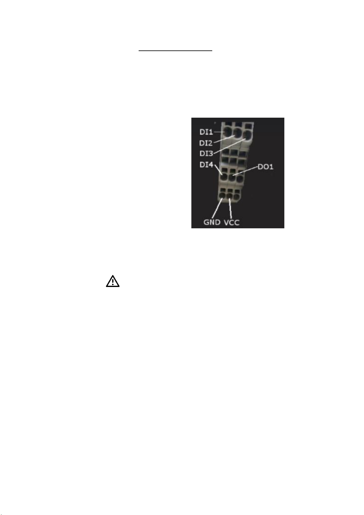
EXTERNAL SIGNAL
DIGITAL INPUTS AND DIGITAL OUTPUTS
Charger supports connecting four digital inputs and one digital output.
Inputs and output are operating on 12 VDC, and maximal allowed load is
100 mA. Check pinout on the image below.
Figure 4: Pins of connector for digital inputs and output
The use and logic of these digital input and outputs is settable via web
interface of the charging station.
Do not use external 12 VDC or 5 VDC for power supply. Digital output
allows maximal load of 100 mA! Be careful not to make short circuit,
which could be dangerous to persons and could also damage the
charging station.

13 | 57
Etrel INCH DUO | Electrical Installation Specifics
Technical
|
3 CABLE CROSS-SECTION SELECTION
The required cable cross-section is determined considering the maximum
current, the allowable voltage drop and the expected short-circuit
current. Cross-section can be determined by calculation or from a table,
in the usual way, in accordance with IEC 60364-5-52.
When determining the cross-section of the cables, it is also necessary to
include the method of installation, the material of the conductors and the
insulation material. The temperature conditions at the location and the
length of the cable also have an impact.
In general, the cable cross-section for the INCH DUO connection is around
10 - 25 mm2, dependant on the installation method. Larger distances or
clustering of several charging stations could require cables with larger
cross-section. Direct connection of INCH DUO is possible for cables of
cross-section of up to 50 mm2. With use of additional clamps, it is possible
to connect cables with cross-section of up to 95 mm2.
We recommend that at least the specified cable cross-section is selected
for all phase conductors, for the neutral conductor and for the protective
conductor. When choosing cables with a larger cross-section, the losses
will be smaller, which is especially important for longer cable routes.
MINIMUM CABLES CROSS-SECTION
The calculation of necessary cables cross-sections should be part of
electrical project and should consider the specifics of the actual location.
The plan of installation should be prepared by licensed electrician or
electrical planner in accordance with national legislation. Values given in
this chapter are only informational.
The cables cross-sections are determined by three criteria:
•Continuous operating current.
•Voltage drop.
•Short circuit withstand.
CONTINUOUS OPERATING CURRENT
The cross-section of cables must be large enough that continuous
charging with maximal current is safe and does not damage the cables.
Different installation options and environmental conditions are possible.
In the following table, the installation method can be checked for the
minimum cable cross-section when connecting one INCH DUO charging
station. These values apply for copper conductors with XLPE insulation at
reference air temperature of 35 ° C. For installation of cables in the
ground, temperature of the ground is set as 25 ° C and soil thermal
resistivity as 2.5 K*m/W. Charging current of 64 A is being considered.
14 | 57
Etrel INCH DUO | Electrical Installation Specifics
Technical
|
Table 1: Minimum cable cross-section for continuous operating current of 64 A.
A1 - Insulated single core conductors in conduit in a
thermally insulated wall
A2 - Multicore cable in conduit in a thermally insulated wall
This method also applies to single core or multicore cables
installed directly in a thermally insulated wall (use methods
A1 and A2 respectively), conductors installed in mouldings,
architraves and window frames.
A1, A2:
16 mm2
B1 - Insulated single core conductors in conduit on a wall
B2 - Multicore cable in conduit on a wall
This method applies when a conduit is installed inside a wall,
against a wall or spaced less than 0.3 x D (overall diameter
of the cable) from the wall. Method B also applies for cables
installed in trunking / cable duct against a wall or suspended
from a wall and cables installed in building cavities.
B1, B2:
16 mm2
C - Single core or multi-core cable on a wooden wall
This method also applies to cables fixed directly to walls or
ceilings, suspended from ceilings, installed on unperforated
cable trays (run horizontally or vertically), and installed
directly in a masonry wall (with thermal resistivity less than
2 K·m/W).
C:
10 mm2
D1 - Multicore or single core cables installed in conduit
buried in the ground
D2 - Multicore or single core cables buried directly in the
ground
D1, D2:
16 mm2
E - Multicore cable in free-air
This method applies to cables installed on cable ladder,
perforated cable tray or cleats provided that the cable is
spaced more than 0.3 x D (overall diameter of the cable)
from the wall. Note that cables installed on unperforated
cable trays are classified under Method C.
E:
10 mm2
F - Single core cables touching in free-air
This method applies to cables installed on cable ladder,
perforated cable tray or cleats provided that the cable is
spaced more than 0.3 x D (overall diameter of the cable)
from the wall. Note that cables installed on unperforated
cable trays are classified under Method C.
F:
25 mm2
G - Single-core cables laid flat and spaced in free-air
This method applies to cables installed on cable ladder,
perforated cable tray or cleats provided that the cable is
spaced more than 0.3 x D (overall diameter of the cable)
from the wall and with at least 1 x D spacings between
cables. Note that cables installed on unperforated cable
trays are classified under Method C. This method also
applies to cables installed in air supported by insulators.
G:
25 mm2
At sites, where the cross-section of already existent cables is smaller than
recommended minimum, the limitation of maximal current can be made
in the charging station’s web interface to allow the connection of charging
station, without the need to replace all the cables.
15 | 57
Etrel INCH DUO | Electrical Installation Specifics
Technical
|
VOLTAGE DROP
The requirement for the maximum voltage drop of the installation can be
different across different countries. Usually, it is required that the voltage
drop of the installation is below 4 % (or in some cases below 5 %).
The length of the conductors and charging current are major factors
determining the adequacy of cables cross-section, however voltage drop
occurs on other components or devices as well. Because of it, some
reserve should be considered when selecting cables cross-section.
Table 2: Voltage drop in conductors with 10 mm2cable cross-section and charging
current of 64 A.
Charging current
Conductor
Conductor
64 A
10 mm2
10 mm2
Single phase
Three phase
L - length [m]
Voltage drop [%]
Voltage drop [%]
10
1,09
0,94
20
2,18
1,88
30
3,26
2,83
40
4,35
3,77
Table 3: Voltage drop in conductors with 16 mm2cable cross-section and charging
current of 64 A.
Charging current
Conductor
Conductor
64 A
16 mm2
16 mm2
Single phase
Three phase
L - length [m]
Voltage drop [%]
Voltage drop [%]
10
0,69
0,60
20
1,38
1,19
30
2,07
1,79
40
2,75
2,39
50
3,44
2,98
60
4,13
3,58
Lower voltage drop also means that the power losses of charging process
will be lower. The life cycle assessment and calculation of benefit of using
cables with larger cross-section could help mitigate the higher cost of
investment.
16 | 57
Etrel INCH DUO | Electrical Installation Specifics
Technical
|
Table 4: Voltage drop in conductors with 25 mm2cable cross-section and charging
current of 64 A.
Charging current
Conductor
Conductor
64 A
25 mm2
25 mm2
Single phase
Three phase
L - length [m]
Voltage drop [%]
Voltage drop [%]
10
0,45
0,39
20
0,90
0,78
30
1,35
1,17
40
1,80
1,56
50
2,25
1,95
60
2,70
2,33
70
3,14
2,72
80
3,59
3,11
90
4,04
3,50
Table 5: Voltage drop in conductors with 35 mm2cable cross-section and charging
current of 64 A.
Charging current
Conductor
Conductor
64 A
35 mm2
35 mm2
Single phase
Three phase
L - length [m]
Voltage drop [%]
Voltage drop [%]
40
1,31
1,13
50
1,64
1,42
60
1,97
1,70
70
2,29
1,99
80
2,62
2,27
90
2,95
2,55
100
3,28
2,84
110
3,60
3,12
120
3,93
3,40
SHORT CIRCUIT WITHSTAND
Charging station INCH DUO has already installed miniature circuit
breakers which protect against overload and short circuit. This protection
can also be part of installation with different tripping characteristics.
Short circuit protection lowers the possible short-circuit and its duration
that downstream installed devices can be subjected to. Normally, 2 kA
short circuit of 10 ms duration could be considered for calculations of
cables cross-section to withstand short circuit.
Cable with cross-section of 6 mm2is enough to withstand 5 kA, 20 ms.
This value suggests that short-circuit withstand will not be the strictest
criterion.
17 | 57
Etrel INCH DUO | Electrical Installation Specifics
Technical
|
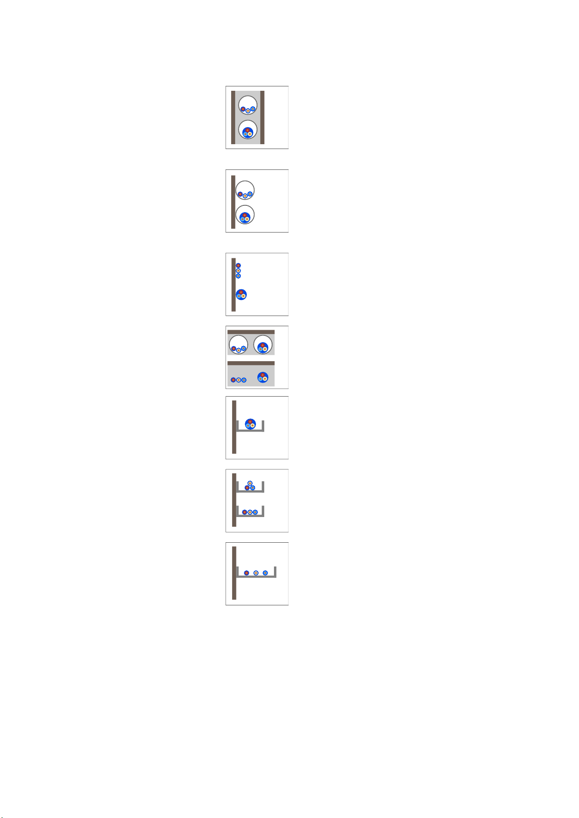
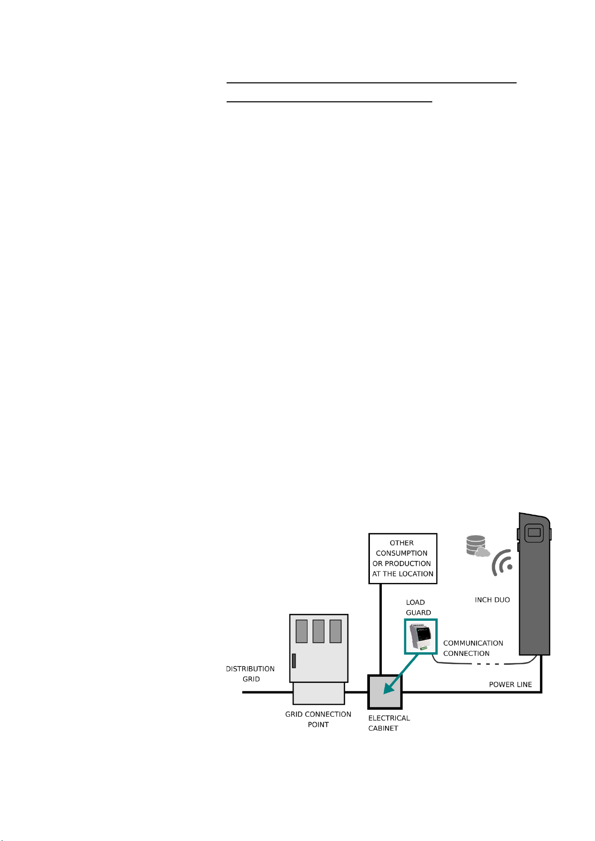
OTHER CONSUMPTION OR PRODUCTION OF
ELECTRICITY AT THE LOCATION
In cases, where there are other loads at the location and there is a
possibility that the total load (other loads + charging) overcomes the
limitation of the grid connection point, the charging should be controlled.
Because the charging station needs information of other loads (or
production) to be able to react appropriately, Etrel Load Guard device can
be used.
LOAD GUARD
By using Load Guard device, other loads or production can be measured
and used in overload prevention algorithms:
•Static limit of maximum allowed charging current per phase.
•Static limit of maximum allowed charging current per phase in
case connection with Load Guard sensor or with Back-End System
is lost.
•Detection and visualisation of available supply and automatic
adjustment of charging power.
•Detection and visualisation of surplus energy returned to the grid
(Production from renewable energy sources).
When the user connects EV to charger, and prior to beginning of charging,
the charger determines the current available for charging as the
difference between the rated current of the main fuse (reduced by a
safety margin that can be pre-set by the user via charger’s web interface)
and the last measurement received from Load guard.
Figure 5: Use of additional consumption data to prevent overload

18 | 57
Etrel INCH DUO | Electrical Installation Specifics
Technical
|
When there is local production of energy present at the location (e.g.,
photovoltaics), the available charging current can be higher, and the use
of Load Guard make possible to always charge with maximum available
current.
Figure 6: Use of additional consumption and production data to prevent overload
Other manuals for INCH DUO
1
Table of contents
Other Etrel Batteries Charger manuals


