Charmilles E110-D10 User manual

1
r
r
2
-
-
[)
)
Published
by
ATELIERS
DES
CHARMILLES
S.A.
GENEVA
-
SWITZERLAND
The
handing
over
to
a
third
party,
the
publication
or
the
reproduction
even
partial
of
this
document
without
any
authorization
are
forbidden.
All
rights
for
modifications
reserved.
Printed
in
tzerl
MD10222370E
INDEX
1
-
UNPACKING
2
-
TRANSPORTATION
2.1
-
The
machine
2.2
-
The
counterweight
2.3
-
The
generator
3 -OPERATING
SITE
4 -INSTALLATION
5 -LEVELLING
OF
THE
MACHINE
6
-
DEGREASING
OF
THE
MACHINE
7
-
MACHINE
ERECTION
7.1
-Mechanical
assembling
7.2
-
Setting
up
of
the
hydraulic
circuit
7.3
-Checking
for
correct
erection
7.3.1
-
Checking
of
the
hydraulic
7.3.2
-
Checking
of
the
dielectric
7.
3.
3 -
Checking
of
the
generator
circuit
circuit
7.
3.
4
--
Checking
of
the
angular
position
of
the
magnetic
chuck
8
-
DESCRIPTION
8.1
-
Generalities
8.2
-
Carriage
8.3
-
Column
8.4
-
Frame
8.5
-
Dielectric
tank
8.6
-
X
and
y
table
8.7
-
Work
tank
8.8
-
Servo-mechanism
8.9
-
Hydraulic
circuit
1
3
3
3
3
5
5
7
9
ll
ll
15
17
17
17
19
19
21
21
23
25
25
27
29
31
33
35
-
Dielectric
circuit
-
Electrical
circuit
8.10
8.11
8.12
-
Interconnecting
tubing
and
electrical
connections
8.13
-
Safety
devices
and
depth
stop
9
-
LUBRICATION
10
-
CLEANING
ll
-
TROUBLE
SHOOTING
12
-
OPERATION
12.1
-
Carriage
12.2
--
X
andY
table
12.3
-Work
tank
12.4
-
Machine
start
12.5
-Clamping
of
the
workpiece
12.6
--
Up
and
down
manual
control
of
chuck
travel
12.7
- Edge
finder
12.8
-
Depth
stop
12.9
-
Indicator
12.10
-
Flushing
mode
12.11
-
Swivel-seat
installation
12.12
- Chuck
installation
12.13
-
Set
up
of
the
electrode
holder
to
the
magnetic
chuck
12.14
-Angular
alignment
of
the
magnetic
12.15
-Alignments
13
-
-
13.1
13.2
13.3
-
Generalities
-
Description
--
Handling
of
the
acces
es
13.4
-
Checking
adjustment
of
the
accessories
37
39
41
43
45
45
47
49
49
49
49
51
51
51
51
53
55
57
59
59
59
61
61
67
67
69
71
73
-
1 -
l
--
UNPACKING
It
is
recommended
that
the
following
procedure
observed
for
removal
of
the
machine
from
the
packing
crate:
l.
Remove
the
top
cover
of
the
crate
(fig.
1)
.
2 •
Remove
the
two
beams
that
hold
the
machine
(fig.
2)
•
3.
Remove
the
two
long
side-flats
of
the
case
(fig.
3)
•
4 •
Remove
the
two
lateral
head-pieces
(fig.
4)
•
5.
Cut
the
hoop-iron
strips.
This
will
expose,
from
left
to
right
on
the
bottom
of
the
crate
(fig.
5):
- 1
machine,
type
D
10,
- 1
case
containing
accessories,
- l
generator
(800),.
- 1
tank
for
the
dielectric
fluid
(500)
2
pipes
(G &
H)
,
-
several
hose
clamps.
6.
Remove
the
above
units
from
the
bottom
of
crate
in
the
following
order:
(first
loosen
the
hold-down
beams)
the
case
of
accesso~ies,
-
the
generator
(800)
(refer
to
paragraph
on
uTRANSPORTATION"),
-the
pipes
(G
&
H),
-
the
tank
(500)
(refer
to
paragraph
on
''TRANSPORTATION"),
7.
Remove
the
two
wood
beams
that
clamp
down
the
metal
bars
used
to
secure
machine
(fig.
6).
8.
Lift
the
machine
and
remove
it
from
the
base
of
the
crate.

Fig
2
Fig
4
800
Fig
5
Fig
6
-
3
-
2
-
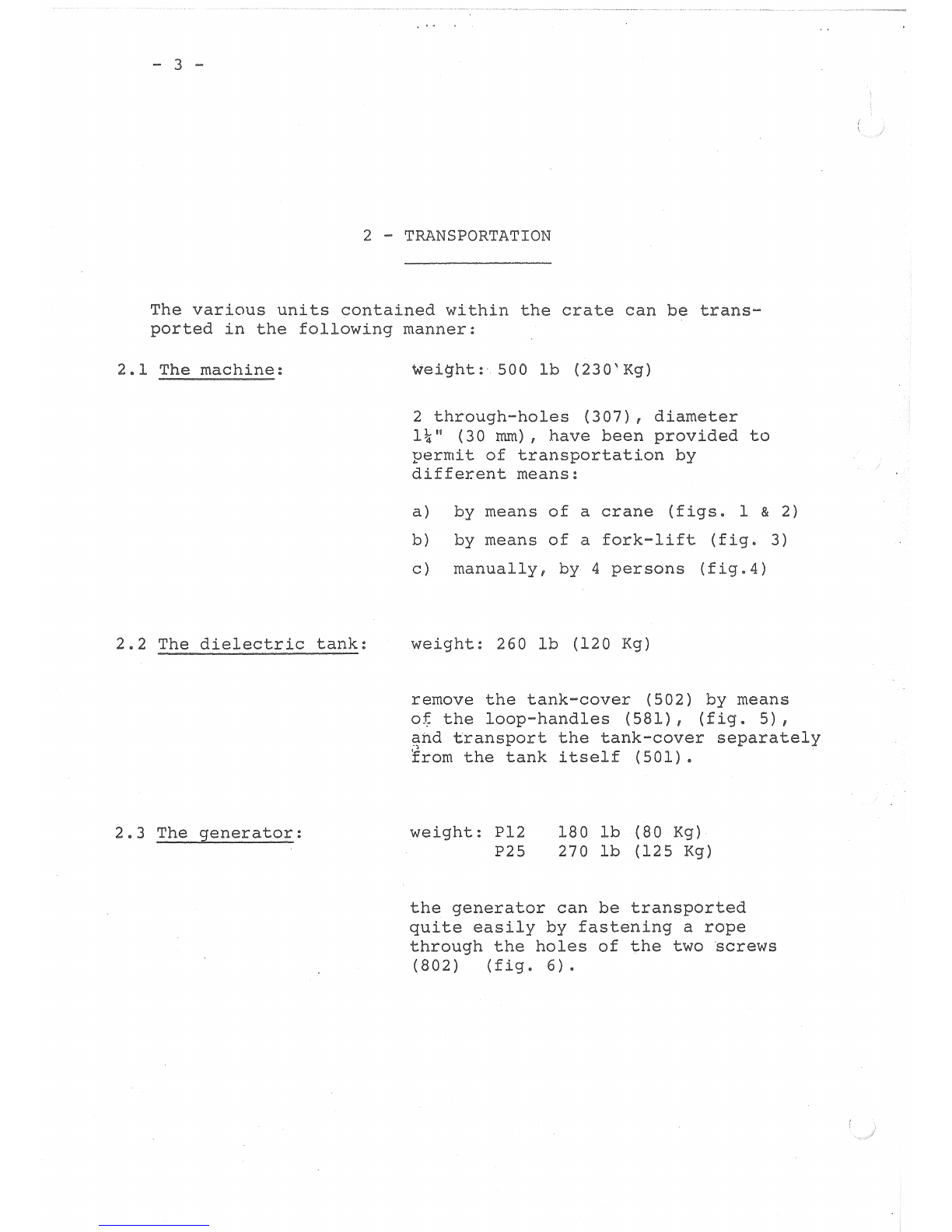
TRANSPORTATION
The
various
units
contained
within
the
crate
can
be
trans-
ported
in
the
following
manner:
2.1
The
machine:
2.2
The
dielectric
tank:
2.3
The
generator:
wei~ht:
soo
lb
(230'Kg)
2
through-holes
(307),
diameter
1~"
(30
mrn),
have
been
provided
to
permit
of
transportation
by
different
means:
a)
by
means
of
a
crane
(figs.
1 & 2)
b)
by
means
of
a
fork-lift
(fig.
3)
c)
manually,
by
4
persons
(fig.4)
weight:
260
1b
(120
Kg)
remove
the
tank-cover
(502)
by
means
o~
the
loop-handles
(581),
(fig.
5),
and
transport
the
tank-cover
separately
Irom
the
tank
itself
(501).
weight:
Pl2
P25
180
lb
(80
Kg)
270
lb
(125
Kg)
the
generator
can
be
transported
quite
easily
by
fastening
a
rope
through
the
holes
of
the
two
screws
(802)
(fig.
6)'
Fig
4
581
Fig 5
301
fig
1
Fig
3
Fig
6
307
Fig
2
802

-
5
-
3
-
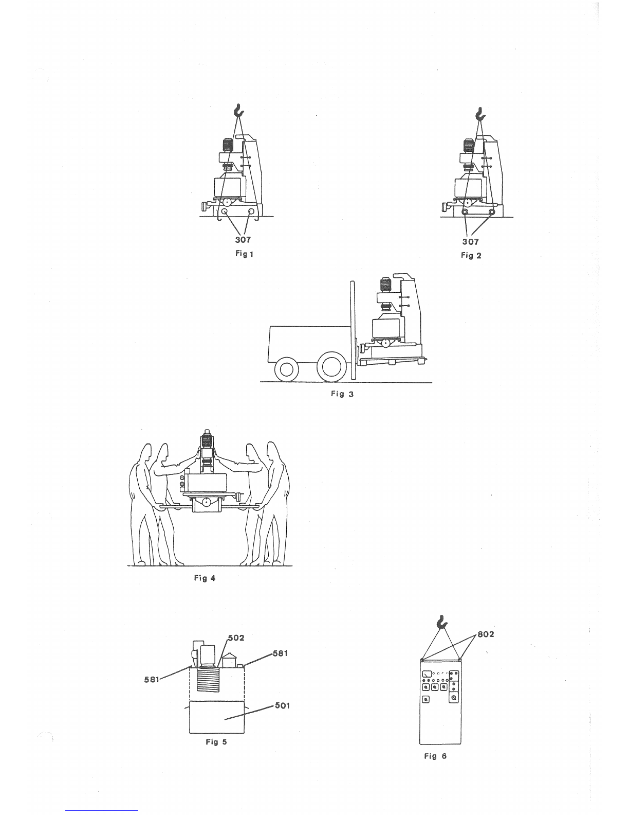
OPERATING
SI.TE
We
recommend
that
the
machine
installed
in
a
clo
and
clean
room,
or
at
least,
that
it
located
in
a
site
is
well
protected
against
dirt,
dust
and
grit
usually
encoun-
tered
in
workshops.
~he
floor
plan
(fig.
1)
takes
care
of
not
only
the
actual
space
taken
up
by
the
machine,
the
generator
and
the
dielectric
tank,
but
also
the
space
required
for
their
correct
location
in
relation
to
each
other
and
the
space
necessary
for
normal
operating
and
maintenance
of
the
complete
installation.
The
dotted
line
refers
to
cases
in
which
the
dielectric
tank
is
located
in
the
rear
of
the
machine
(refer
to
paragraph
on
11
INSTALLATION
11
).
On
the
site
chosen,
provision
must
be
made
for
:
-
A
3-phase,
3
KVA
electrical
supply
outlet,
complete
with
all
necessary
protective
devices
(fuses,
over-
load
relays),
to
power
the
installation.
- A
suitable
system
for
-
supply
and
disposal
of
coolant
water
at
a
pressure
not
to
exceed
120
PSI
(10
Kg/cm2),
pipe
~
3/8"
(10
mm).
-
Efficient
ventilation
or
an
installation
for
the
exhaust
of
fumes.
-
An
adequate
lighting
installation.
4
-
INSTALLATION
It
is
necessary
to
comply
with
two
very
important
considerations
a)
The
dielectric
tank
must
always
be
located
at
a
lower
level
than
the
machine.
b)
The
generator
must
be
located
as
close
as
possible
to,
and
on
the
right-hand
side
of
the
machine.
1§~
possibility
:
on
a
single
workbench.
Minimum
dimensions
2~~
possibility
of
the
bench
area:
60"
x
32"
(1500
x
800
mm).
If
the
dielectric
tank
(500)
is
located
immediately
underneath
the
machine,
the
height
available
below
the
workbench
must
be
of
at
least
33"
(830
mm)
(fig.
2).
on
two
workbenches.
Minimum
dimensions
of
the
area
of
each
workbench:
30"
x
32"
(1500
x
800
mm).
If
the
dielectric
tank
(500)
is
located
immediate
underneath
the
machine,
the
height
available
below
the
workbench
must
be
of
at
t 33
11
(830
mm)
(fig.
3).
The
tank
for
the
dielectric
fluid
may
be
installed
either
a)
immediately
underneath
the
machine
(fig.
4)
b)
in
the
rear
or
at
the
side
of
the
machine
(figs.
5 &
6).
60
em
\
-
3KVA
-
.J
/
----
Fig
5
50
cm
150
em
Fig
1
Fig
3
E
co
60
em
E
rnm
Fig
2
Fig
4
Fig
6,
co
E
-
7
-
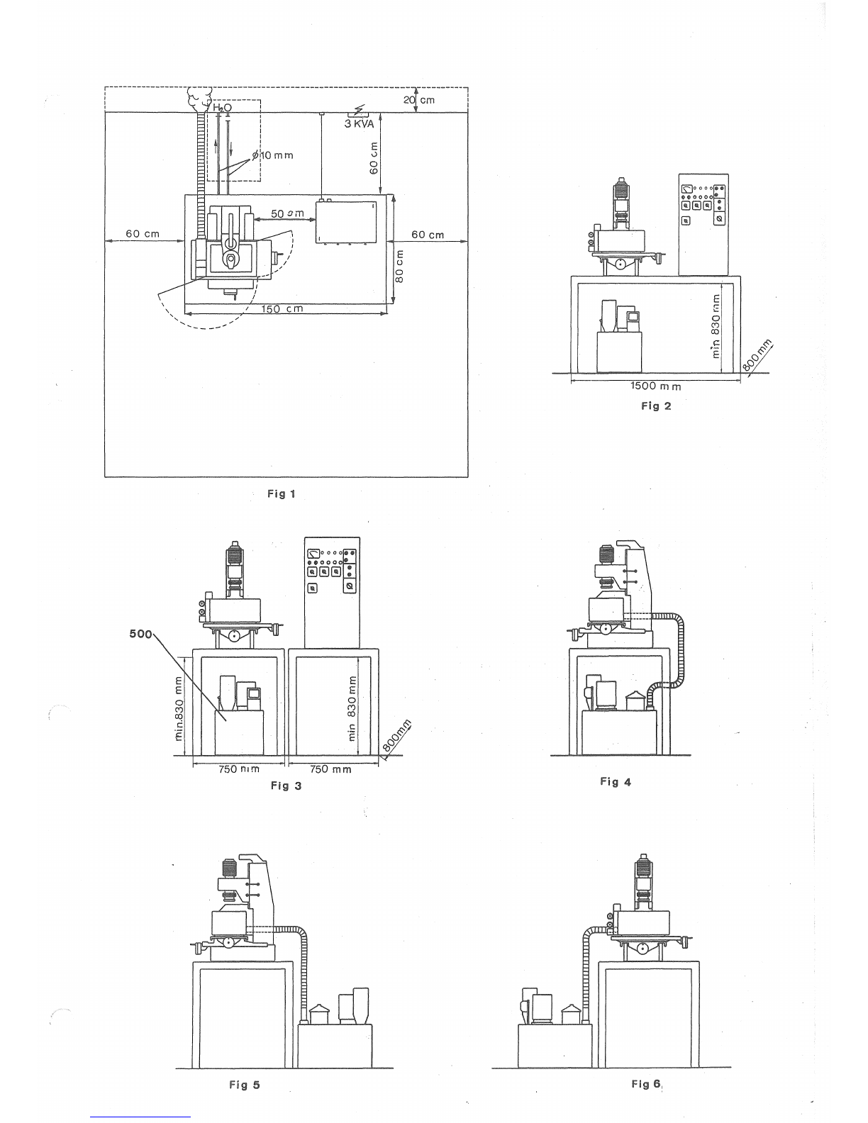
5
-
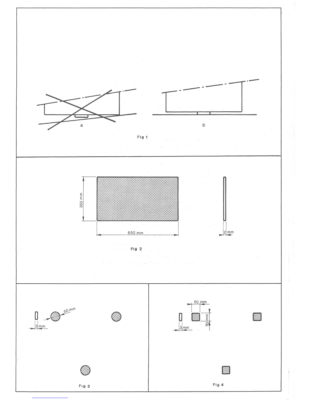
LEVELLING
OF
THE
MACHINE
The
machine
must
never
fastened
to
the
workbench
by
bolts
or
screws.
It
must
stand
free
on
the
bench.
The
frame
of
the
machine
must
not
touch
the
bench,
it
should
rest
firmly
on
the
three
feet
provided
for
this
purpose
(fig.
1 a &
b)
.
If
the
surface
of
the
bench
is
not
of
sufficient
hardness,
bearing-plates
should
be
placed
under
the
feet
to
distribute
the
weight
of
the
machine
over
a
larger
area.
It
is
not
advisable
to
place
more
than
one
bearing-plate
under
each
foot.
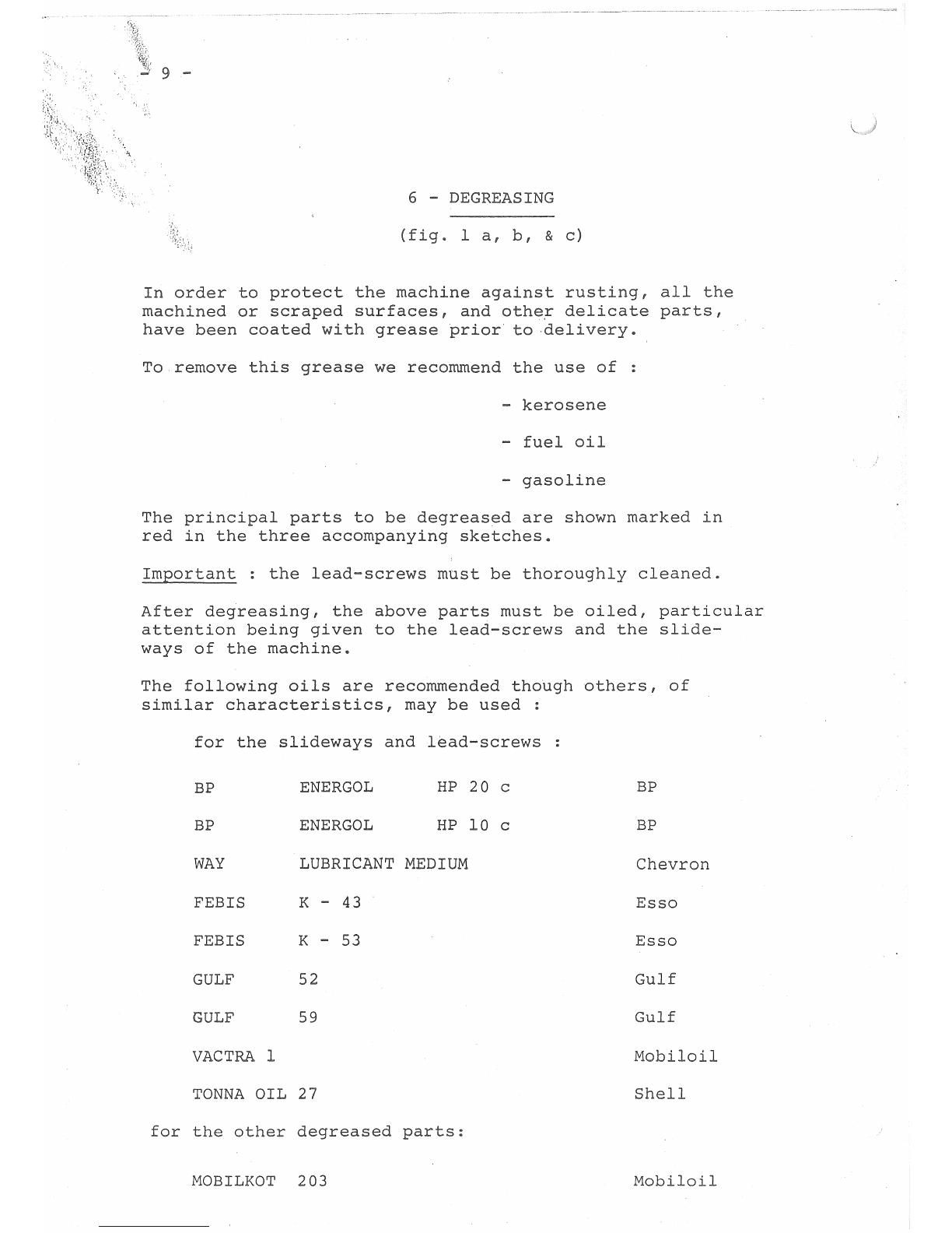
The
three
following
arrangements
are
suggested
a)
the
use
of
a
single
metal
sheet
(650
X
350
X 2
rom)
(fig.
2)
26"
X
14"
X
3/32"
b)
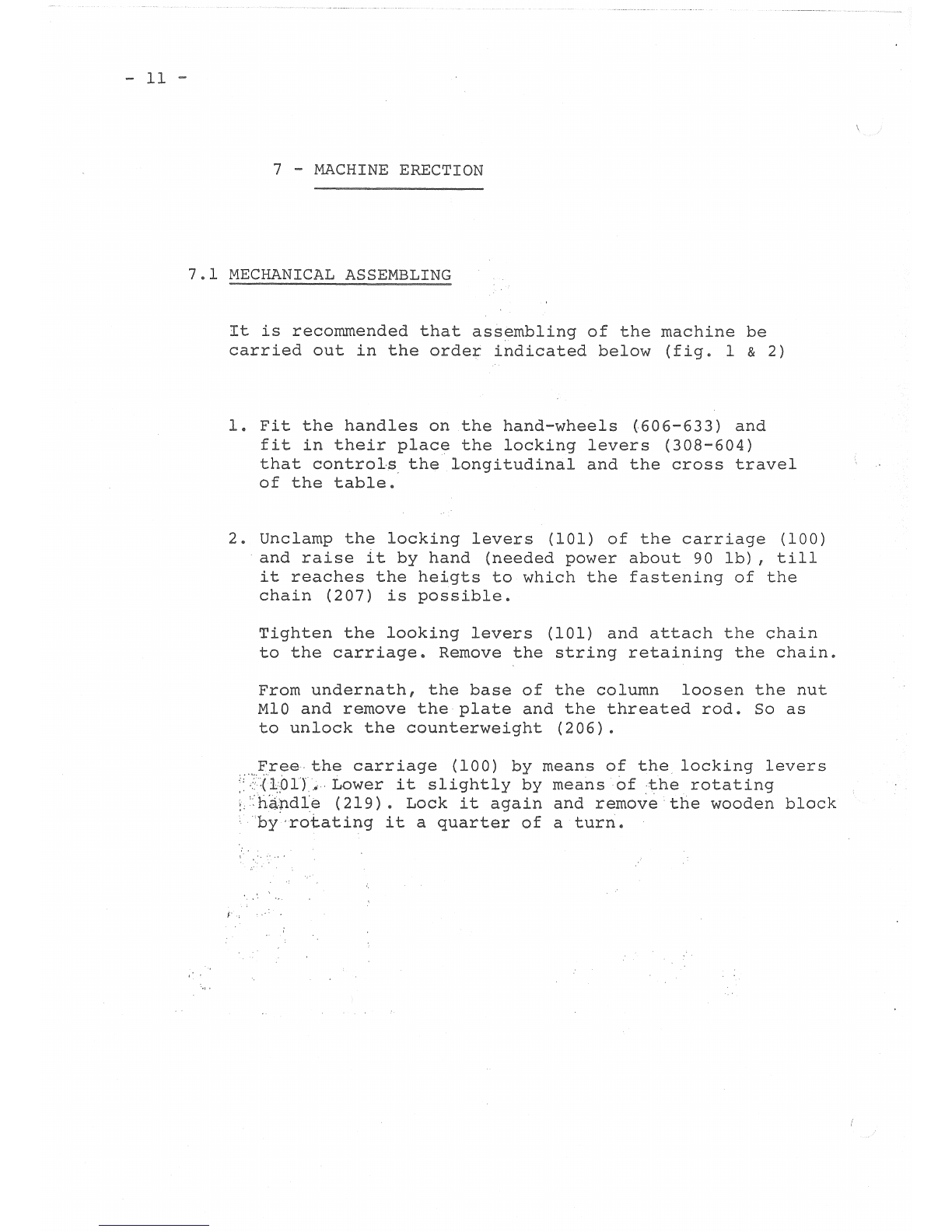
the
use
of
3
round
discs
~
2"
x
1/8"
(~
50
x 3
mm)
(fig.
3)
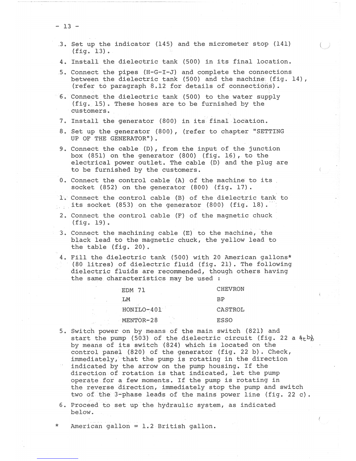
c)
the
use
of
3
square
plates
of
(fig.
4)
8"
(3
mm)
thickness
The
top
of
the
workbench
should
be
as
nearly
horizontal
as
possible.
For
more
accurate
levelling,
make
use
of
shim-
stock
placed
either
under
the
bench
feet
or
under
the
bearing-plates
or
use
bearing-plates
of
different
thickness.
Levelling
to
an
accuracy
of
0.5%
is
sufficient,
even
1%
will
be
satisfactory
if
the
slope
helps
the
evacuation
of
the
dielectric
fluid.
E
E
Fig
fig
2
-
b
Fig
4
9
-
6
-
DEGREASING
(fig.
l
a,
b,
&
c)
In
order
to
protect
the
machine
against
rusting,
all
the
machined
or
scraped
surfaces,
and
othe~
delicate
parts,
have
been
coated
with
grease
prior
to
-delivery.
To
remove
this
grease
we
recommend
the
use
of
-
kerosene
-
fuel
oil
-
gasoline
The
principal
parts
to
be
degreased
are
shown
marked
in
red
in
the
three
accompanying
sketches
Important
:
the
lead-screws
must
be
thoroughly
cleaned.
After
degreasing,
the
above
parts
must
be
oiled,
particular
attention
being
given
to
the
lead-screws
and
the
slide-
ways
of
the
machine.
The
following
oils
are
recommended
though
others,
of
similar
characteristics,
may
be
used
:
for
the
slideways
and
lead-screws
BP
ENERGOL
HP
20
c
BP
BP
ENERGOL
HP
10
c
BP
WAY
LUBRICANT
MEDIUM
Chevron
FEB
IS
K - 43
Esso
FEB
IS
K -
53
Esso
GULF
52
Gulf
GULF
59
Gulf
VACTRA
1
Mobiloil
TONNA
OIL
27
Shell
for
the
other
degreased
parts:
MOBILKOT
203
Mobiloil

F1g 1
-
11
-
7
-
MACHINE
ERECTION
7.1
MECHANICAL
ASSEMBLING
It
is
recommended
that
assembling
of
the
machine
be
carried
out
in
the
order
indicated
below
(f
. 1 & 2)
1.
Fit
the
handles
on
the
hand-wheels
(606-633)
and
fit
in
their
place
the
locking
levers
(308-604)
that
controls
the
longitudinal
and
the
cross
travel
of
the
table.
2.
Unclamp
the
locking
levers
(101)
of
the
carriage
(100)
and
raise
it
by
hand
(needed
power
about
90
lb),
till
it
reaches
the
heigts
to
which
the
fastening
of
the
chain
(207)
is
possible.
Tighten
the
looking
levers
(101)
and
attach
the
chain
to
the
carriage.
Remove
the
string
retaining
the
chain.
From
undernath,
the
base
of
the
column
loosen
the
nut
MlO
and
remove
the
plate
and
the
threated
rod.
So
as
to
unlock
the
counterweight
(206).
Freethe
carriage
(100)
by
means
of
the
locking
levers
(
1:01)
...
Lower
it
slightly
by
means
of
the
rotating
:'handle
(219).
Lock
it
again
and
remove
the
wooden
block
by·rotating
it
a
quarter
of
a
turn.

219
206
606
--
13
-
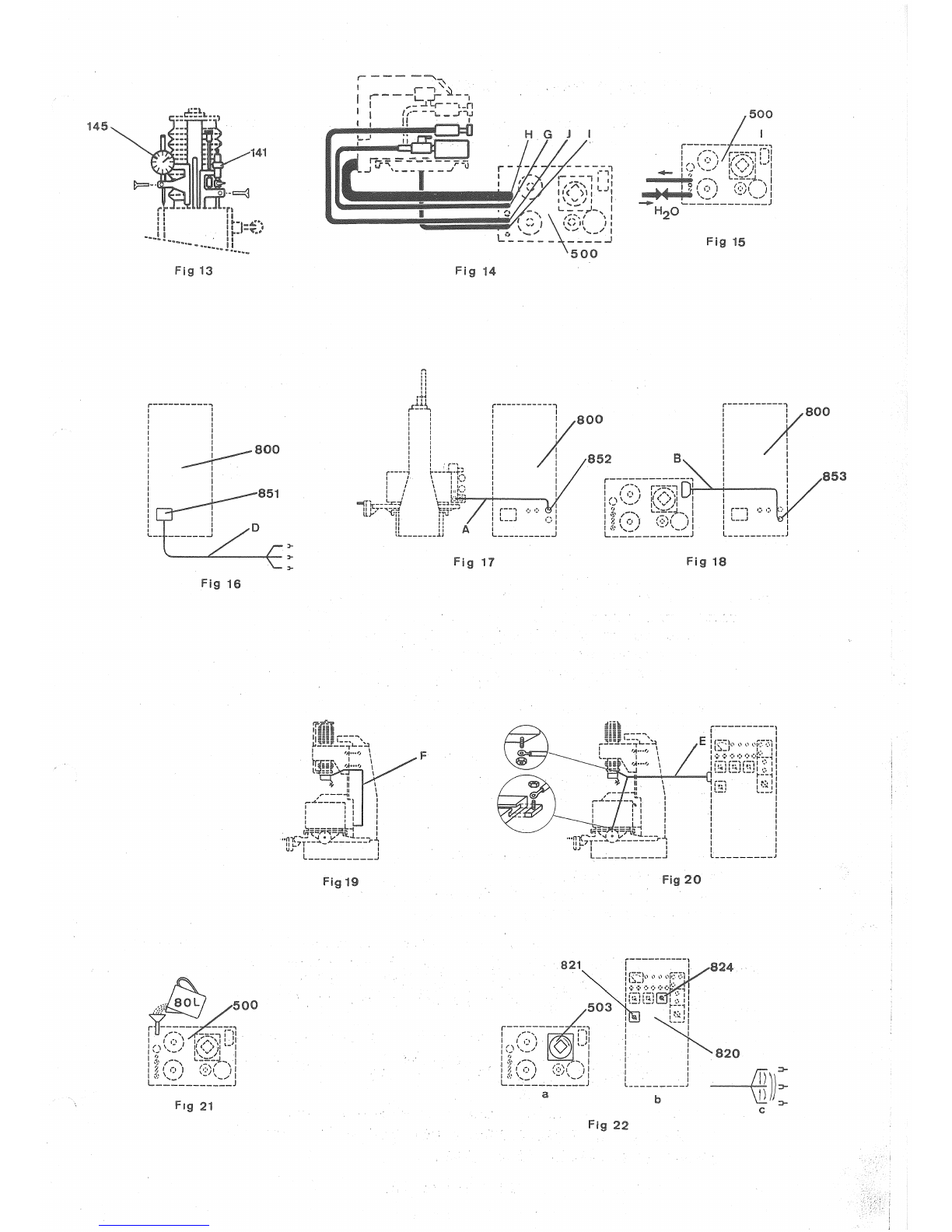
*
.3.
Set
the
indicator
(145)
and
the
micrometer
stop
(141)
(fig.
13).
4.
Install
the
dielectric
tank
(500)
in
its
final
location.
5.
Connect
the
pipes
(H-G-I-J)
and
complete
the
connections
between
the
dielectric
tank
(500)
and
the
machine
(fig.
14),
(refer
to
paragraph
8.12
for
details
of
connections).
6.
Connect
the
dielectric
tank
(500)
to
the
water
supply
(fig.
15).
These
hoses
are
to
be
furnished
the
customers.
7.
Install
the
generator
(800)
in
its
final.location.
8.
Set
up
the
generator
(800),
(refer
to
chapter
11
SETTING
UP
OF
THE
GENERATOR").
9.
Connect
the
cable
(D),
from
the
input
of
the
junction
box
(851)
on
the
generator
(800)
(fig.
16),
to
the
electrical
power
outlet
•.
The
cable
(D)
and
the
plug
are
to
be
furnished
by
the
customers.
0.
Connect
the
control
cable
(A)
of
the
machina
to
its
socket
(852)
on
the
generator
(800)
(fig.
17).
1.
Connect
the
control
cable
(B)
of
the
dielectric
tank
to
its
socket
(853)
on
the
generator
(800)
(fig.
18).
2.
Connect
the
control
cable
(F)
of
the
magnetic
chuck
(fig.
19).
3.
Connect
the
machining
cable
(E)
to
the
machine,
the
black
lead
to
the
magnetic
chuck,
the
yellow
lead
to
the
table
(fig.
20).
4.
Fill
the
dielectric
tank
(500)
wi
20
American
gallons*
(80
litres)
of
dielectric
fluid
(fig.
21).
The
following
dielectric
fluids
are
recommended,
though
others
having
the
same
characteristics
may
be
used
EDM
71
LM
HONIL0-401
MENTOR-28
CHEVRON
BP
CASTROL
ESSO
5.
Switch
power
on
means
of
the
main
switch
(821)
and
start
the
pump
(503)
of
the
dielectric
circuit
(fig.
22
a
& b
by
means
of
its
switch
(824)
which
is
located
on
the
control
panel
(820)
of
the
generator
(fig.
22
b).
Check,
immediately,
that
the
pump
is
rotating
in
the
direction
indicated
the
arrow
on
the
pump
housing.
If
the
direction
of
rotation
is
that
indicated,
let
pump
operate
for
a
moments.
If
the
pump
i~
totating
in
the
reverse
direction,
immediately
stop
the
pump
and
switch
two
the
3-phase
leads
of
the
mains
power
line
(fig.
22
c).
6.
Proceed
to
set
up
the
hydraulic
system,
as
indicated
below.
American
gallon
=
1.2
British
gallon.
145
Fig
15
Fig
13
Fig
14
800
:
852
: B
800
:
:
853
'
Fig
17
Fig
18
Fig
Hi
F
Fig
19
Fig
20
821
Fig
22

-
15
-
7.2
-
UP
OF
THE
HYDRAULIC
CIRCUIT
1.
Remove
the
metal
plug
fro~
the
free
end
the
rubber
pipe
but
leave
the
diaphragm
plug
on
rubber
pipe
(K)
(fig.
23).
2.
Fill
a
very
clean
can
wi
l.
5
American:
gallon*
( 5
li
tres)
of
hydraulic
oil.
We
recommend
the
use
of
the
following
oils
though
others
having
similar
characteristics
be
used:
ENERGOL-HYDRAULIC-40
CHEVRON
5 X
SPINESSO
-
34
VELOCIT 6
PENNOL
GC
-
34
TELLUS
OIL
-
15
PURFINA-HYDRAU
-
125/12
BP
Chevron
Esso
Mobiloil
Pennsylvania
Shell
Socal
3.
Insert
the
ends
of
the
rubber
pipes
(M
&
K)
into
the
can,
without
removing
the
diaphragm
plug
from
pipe
(K),
then
pour
a
small
quantity
of
oil
into
the
filter
(593)
(fig.
24).
4.
Start
up
the
pump
(590)
(fig.
25
a)
of
the
hydraulic
circuit
by
means
of
the
switch
(823)
(fig.
25
b)
located
on
the
control
panel
(820)
of
the
generator,
make
sure
that
the
direction
of
rotation
of
the
pump
is
correct
and
then
let
the
oil
circulate
for
at
least
two
hours
in
order
to
filter
out
any
impurities
it
may
contain.
5.
Having
let
the
oil
circulate
for
a
period
of
two
hours,
switch
off
the
hydraulic
pump
(590)
by
means
of
the
switch
(823).
6.
Remove
the
adhesive
tapes
covering
the
openings
(108-109-
125)
and
also
the
rubber
guard
placed
as
protection
over
the
nozzle
(104)
(fig.
26).
7.
Remove
the
diaphragm
plug
from
the
end
of
pipe
(K)
and
fit
this
rubber
pipe
onto
nozzle
(104)
(fig.
27).
Start
up
the
pump
(590)
again
by
means
of
tch
(823).
The
piston
(121)
will
then
rise
automatically
to
the
highest
point
of
its
stroke.
8.
As
soon
as
the
oil
within
the
indicator
tube
(107)
reaches
a
level
intermediate
between
5"
(125
mm)
(minimum)
and
5~
(
14
0
mm)
(maximum)
(fig.
28)
,
switch
off
pump
(
590)
of
the
hydraulic
circuit
by
means
of
switch
(823).
9.
Remove
the
rubber
guard
from
nozzle
(106)
and
quickly
insert
the
free
end
of
the
pipe
(M)
into
the
nozzle
in
order
to
prevent
loss
of
oil
(fig.
29).
10.
Connect
the
cable
)
of
the
servo-mechanism
to
the
socket
(108)
located
at
the
upper
end
of
the
oil-level
indicator
tube
(107)
(fig.
30).
*
American
gallon
=
1.2
Bri
sh
gallon

Fig
24
Fig
26
Fig
25
Fig
27
.-
Fig
30
fig
28
Fig
29
Table of contents


