Charnwood W813 User manual

FLOORSTANDING LATHE
OPERATORS MANUAL
MODEL: W813
Charnwood, Cedar Court, Walker Road,
Hilltop Industrial Estate, Bardon Hill, Leicestershire, LE67 1TU
Tel. 01530 516 926 Fax. 01530 516 929

GENERAL SAFETY RULES
WARNING: Do not attempt to operate the machine until you have read thoroughly and
understood completely all instructions, rules, etc. contained in this manual. Failure to comply
may result in accidents involving fire, electric shock, or serious personal injury. Keep this
owner's manual and review frequently for continuous safe operation.
1. Know your machine. For your own safety, read the owner's manual carefully.
Learn its application and limitations, as well as specific potential hazards
pertinent to this machine.
2. Make sure all tools are properly earthed.
3. Keep guards in place and in working order. If a guard must be removed for
maintenance or cleaning, make sure it is properly replaced before using the
machine again.
4. Remove adjusting keys and spanners. Form a habit of checking to see that
the keys and adjusting spanners are removed from the machine before
switched it on.
5. Keep your work area clean. Cluttered areas and workbenches increase the
chance of an accident.
6. Do not use in dangerous environments. Do not use power tools in damp or
wet locations, or expose them to rain. Keep work areas well illuminated.
7. Keep children away. All visitors should be kept a safe distance from the
work area.
8. Make workshop childproof. Use padlocks, master switches and remove
starter keys.
9. Do not force the machine. It will do the job better and be safer at the rate
for which it is designed.
10. Use the right tools. Do not force the machine or attachments to do a job for
which they are not designed. Contact the manufacturer or distributor if there is
any question about the machine's suitability for a particular job.
11. Wear proper apparel. Avoid loose clothing, gloves, ties, rings, bracelets, and
jewellery which could get caught in moving parts. Non-slip footwear is
recommended. Wear protective hair covering to contain long hair.
12. Always use safety glasses. Normal spectacles only have impact resistant lenses.
They are not safety glasses.
13. Do not over-reach. Keep proper footing and balance at all times.
14. Maintain machine in good condition. Keep machine clean for best and safest
performance. Follow instructions for lubrication and changing accessories.

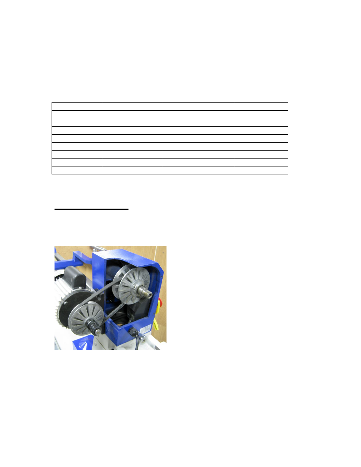
15. Disconnect the machine from power source before servicing and when
changing the drive belt.
16. To avoid accidental starting, make sure the switch is in the OFF position before
plugging in the mains cable.
17. Never leave the machine running unattended. Turn the power off. Do not leave the
machine until it comes to a complete stop.
18. Do not use any power tools while under the effects of drugs, alcohol or medication.
19. Always wear a face or dust mask if operation creates a lot of dust and/or chips.
Always operate the tool in a well ventilated area and provide for proper dust removal.
Use a suitable dust extractor.
ADDITIONAL RULES FOR LATHES
Never attempt to adjust any part of the workpiece whilst the lathe is still in motion. Wait until
the workpiece has come to a complete stop.
1. Ensure that chuck keys, tommy bars and similar items are removed before the lathe
is started.
2. Always stand to one side when you start the lathe so that if anything does fly off e.g.
a loose piece of bark, you will be out of the line-of-fire.
3. When mounting a new piece of timber, rotate the wood through 360oby hand to
ensure that it will not hit the tool rest or the bed of the lathe and then start the lathe at
its slowest speed. When you are certain that that the work is secure and not too out
of balance set the lathe to the normal turning speed.
4. Always check the rotation speed before switching the lathe on to avoid the risk of
starting it whilst it is set to run at too high a speed.
5. The speed of the lathe must be adjusted to suit the size, balance, length and
condition of the timber being turned. The greater the diameter of the work, the slower
the rotation speed needs to be. If the piece you are turning is out of balance, then
you must start turning at a low speed, until it is balanced.
6. The tool must rest firmly on the tool rest before it is brought into contact with the
rotating wood and must never be lifted off the tool rest as long as it is in contact with
the timber.
7. Before sanding, polishing or doing anything else that brings your fingers close to the
work, remove the tool rest. Getting your fingers trapped between the tool rest and the
work will at least be very painful and may cause serious injury.
8. Never wrap the sandpaper of polishing cloth round the work. If it tightens up it will
pull your fingers into contact with the timber and may lead to serious injury.
Important:
Risk of Injury! Wear Eye Wear Ear
Never reach into Protection Protection
Moving parts

Specification
Distance between centres 900mm (36”)
Maximum diameter over bed 310mm (12”)
Maximum diameter (with head rotated) 375mm (15”)
Motor (induction) 550W (3/4hp), 240v
Speeds (10) 500 to 2,000 RPM
Spindle thread 3/4” x 16tpi
Head and tailstock tapers 1MT
Hollow Centres 10mm diameter
Dimensions (WxDxH) 1700 x 450 x 1120mm
Weight 82kg
Rating Hobby
Rating Description
Hobby: Suitable for Weekend DIY'ers and woodworking enthusiasts.
Generally lighter weight machines with lower power ratings and smaller tooling capacities.
Typically only ever used by one person for short periods of time or longer periods of time
infrequently. Machinery should be well maintained in a clean, dry environment such as a
home workshop, garage or timber shed. Expected maximum use of 100 hours annually.
Please Note: Using a product in excess of its rating will void the manufacturer’s free
warranty.
Unpacking the Lathe
All the parts are in one carton. As the lathe is heavy, it should be lifted out of the
carton by two people.

Assembling the Floor Stand
Important: All nuts and bolts should only be fastened finger tight until assembly is
complete.
Using the coach bolts, nuts and plain washers, fix the four legs to the tray, noting that
the legs are left and right handed. Bolt on the top plates, which fit inside the legs.
Square up the assembly and tighten all the nuts and bolts.
Fitting the Lathe to the Stand
Lift (two people are required for
this stage) the lathe bed,
complete with headstock,
tailstock and tool rest on to the
stand (Fig. 2)
Line up the fixing holes in the
bed with those in the stand and
join the two with the 8 long cap
head bolts, spring washers and
nuts. Once all 8 are in place,
tighten them firmly.

Fit the yellow lever onto the
headstock locking shaft.
Secure it in place with the
spring and fixing screw.
Tighten the fixing screw firmly.
When engaged, this lever will
unlock the headstock. Pull the
lever away from the headstock
to rotate it without engaging the
shaft. In this way the handle
can always be placed in a
convenient position.
Insert the drive centre into the headstock spindle and the tail centre into the tailstock
spindle. These may be removed by inserting the knock out bar into the other end of
the spindle and tapping the centre out. It is advisable to put a hand under the centre
when knocking it out, to prevent the centre from falling to the floor and being
damaged.
Bolt the left hand extension bed
to the headstock end of the
main bed using 2 fixing screws.
The headstock on this model
rotates so that large diameter
bowls can be turned.
The tool rest can be fixed to the
extension bed when using the
headstock rotated to the front,
as shown.

Bolt on the accessory
storage tray using the 2
fixing bolts.
Operation
Headstock Drive Centre Tail Centre Tailstock
RPM Display Tool Rest Winding
Handle
Speed Control
On/Off Switch
Extension Bed
Rotation Plunger Accessory Tray
Rotation Lock
Starting and Stopping
Slide up the red switch cover and lift the cover. Press the green ‘on’ button to start
the lathe. Press the red ‘off’ button to stop the lathe. When the switch cover is down,
pressing the cover activates the stop button.
The lathe must be running before you use the speed control. To change the speed
pull the end of the lever towards you, then slowly rotate it to the desired speed. The
revolutions per minute will be indicated on the digital readout.

It is recommended that the lathe is always retuned to the slowest speed before
stopping the lathe. Leaving the lathe at a higher speed when starting, puts more
strain on the motor and may shorten the life span of the motor.
Speed Control
Lever
On/Off Switch
Rotating the Headstock
For safe shipping the headstock is rotated to the front of the machine. To return it to
the normal spindle turning position, undo the yellow rotation lock lever, pull out the
silver rotation plunger and turn the complete headstock anticlockwise through 90
degrees. The plunger will engage again in this position, lock it tight with the yellow
lever.
For certain projects, such as large bowl turning, it may be necessary or more
comfortable to rotate the headstock round to the front, 90 degrees clockwise from the
spindle turning position. The headstock can be locked in any position at 45 degree
intervals.
Adjusting the Tailstock
The tailstock can be moved along the bed of the lathe. To release the tailstock pull
up the silver tailstock locking lever. The tailstock can now freely slide along the bed,
when it is positioned where required, clamp it firmly in place by pressing the lever
firmly down.
Fine adjustment is then made to the tail centre position. Unlock the winding handle
locking lever by half a turn only. Turn the winding handle to enable the tail centre to
be advanced or retracted. It has a travel of 57mm (2½”).
Winding Handle
Winding Handle Locking Lever
Tailstock Locking Lever
Both the headstock and tailstock spindles are
hollow and drive centres or other tools may be
removed by tapping them out with the knockout
bar supplied.

Align the Centres
It is now necessary to check the alignment
of the tailstock to the headstock. Fit both
centres and slide the tailstock down
towards the headstock until both centres
touch and lock the tail centre in place. If
the 2 centres do not meet correctly, undo
the yellow headstock rotation locking lever
and move the headstock slightly until the
centres are aligned. Now lock the
headstock.
It will be necessary to repeat this
procedure whenever the headstock has
been moved away from the spindle turning position.
Adjusting the Toolrest
The toolrest can be moved along the bed of the lathe. To release the toolrest pull up
the silver toolrest locking lever. The toolrest can now freely slide along the bed, when
it is positioned where required, clamp it firmly in place by pressing the lever firmly
down.
Toolrest
Toolrest Height Adjustment Lever
Toolrest Locking Lever
The height of the toolrest can also be adjusted, using the black lever. This type of
lever can rotated to a more convenient position, without moving the thread, by pulling
the lever away from the thread to disengage the ratchet teeth and then rotating it.

Recommended Turning Speeds
Diameter (mm)
Roughing RPM
General Cutting RPM
Finishing RPM
Under 50
1500
3200
3200
50 –100
750
1600
2500
100 –150
500
1000
1700
150 –200
500
800
1250
200 -250
500
650
1000
250 –300
500
530
850
300 - 350
500
500
700
350 - 400
500
500
600
Maintenance
Changing the Drive Belt
Over time the drive belt will become worn and
will need replacing.
Stop the lathe in the fastest speed and
unplug it from the electric supply. Use a hex
key to undo the grub screw which holds the
silver rotating hand wheel onto the spindle.
Unscrew the rotating hand wheel from the
spindle. Locate the 4 retaining screws and
remove the belt cover. Remove the drive belt
from the motor pulleys first.
Install the new belt and then follow these
instructions in reverse.
You can find a video guide in the technical help section of our website or on youtube.

Optional Accessories
There are a wide range of optional accessories available for lathes.
Viper 3 Geared Scroll Chuck
A chuck is used for bowl turning
projects, when the work piece is held
from one end only.
The Viper 3 sized chuck is a perfect
match for the size and power of this
lathe.
DC13MT1
A Drill Chuck with 13mm Capacity, and
an MT1 fitting. Used for boring holes
from the tailstock end.
W834
6 Piece High Speed Steel Chisel Set.
Includes the 6 most commonly used
woodturning chisels, everything you
need for spindle turning.
ML28 LED Work Lamp
If you need better lighting in your workshop this LED light
has a magnetic base which can be attached to the headstock
or the bed of the lathe. A Flexible shaft allows it to be positioned
as required.

Fault Possible Cause Remedy
Machine will not start Power supply not connected Check plug socket is switched on
Fuse in plug has blown Replace fuse
Break in power supply cable Visually check cable, replace in necessary
Loose terminal on switch Remove switch and check connections
Switch failed Replace switch
Machine will not start, a buzzing sound is
heard
Start capacitor failed Replace capacitor
Machine starts to turn but slow speed only
and stalls easily
Failed motor Replace motor
Spindle stalls but motor still running Loose drive belt Replace drive belt
Motor is running but spindle not turning Broken drive belt Replace drive belt
Motor is overheating Too much load on motor Reduce load on motor, make shallower cuts
Airflow to cooling fan is blocked Remove fan cover and clean grill
Spindle rotation slows during cut Excessive depth of cut Make shallower cuts
Chisels are dull Sharpen chisels
Drive Belt Slipping: Check the belt is not
frayed
Replace drive belt
Drive Belt Slipping: Check the spring loaded
pulley moves freely along the shaft
Clean the shaft and use a lubricating sparay
Signs of wear or damage to pulleys Replace motor drive pulleys
CHARNWOOD W813 LATHE TROUBLESHOOTING GUIDE
You can find more information as well as video guides in the technical help section of our website and on youtube.

Declaration of Conformity for CE Marking
Charnwood Declare that Woodworking Lathe, Model W813
Conforms with the following Directives: Machinery Directive 2006/42/EC
Low Voltage Directive 2006/95/EC
EMC Directive 2004/108/EC
And further conforms to the machinery example for which the EC type examination Certificate
No. AM 50170712, AN50170711 and AE50217048 have been issued by TUV Rheinland LGA
Products GmbH, Tillystrasse 2, 90431, Nurnberg.
I hereby declare that equipment named above has been tested and found to comply with the
relevant sections of the above referenced specifications. The machinery complies with all
essential requirements of the directive.
Signed: Dated: 23/04/2010 Location: Leicestershire
Richard Cook, Director
Please dispose of packaging for the product in a responsible manner. It is suitable for
recycling. Help to protect the environment, take the packaging to the local amenity tip
and place into the appropriate recycling bin.
Only for EU countries
Do not dispose of electric tools together with household waste material!
In observance of European Directive 2002/96/EC on waste electrical and electronic
equipment (EEE) and its implementation in accordance with national law, electric tools
that have reached the end of their life must be collected separately and returned to an
environmentally compatible recycling facility.
Your local refuse amenity will have a separate collection area for EEE goods

Charnwood W813 Parts Diagram

Charnwood W813 Parts List
No.
Description
No.
Description
01
Headstock Casting
36B
Tool Rest Post 25mm Diameter
02
Drive Centre 1MT
37B
Ratchet Handle –Tool Rest
03
Faceplate
37C
Ratchet Handle - Tailstock
04
Headstock Spindle
38
Tool Rest Extension
05
Key
39
Tool Rest Body (Banjo)
06
Bearing 6205Z
40A
Tool Rest Locking Handle
07
Bearing 6205Z
41
C Ring/ Circlip
08
Spring
42
Tailstock Cam Hanger
09
Pulley Shift Bracket A
43
Clamp Plate
10
Bearing 6007Z
44
M18 Nyloc Hex Nut
11
C Ring Circlip
45
Tail Centre 1MT
12
Pulley Spindle - Right
46
Tailstock Spindle
13
Drive Belt
47
Tailstock Screw
14
Pulley Spindle –Left
48
Tailstock Casting
15
C Ring Circlip
49
Tailstock Hand Wheel
16
Knock Out Bar
50
Tailstock Locking Handle
17
Screw
51
Grub Screw
18
Rear Headstock Clamp
52
Extension Bed
19
Screw
53
Hex Socket Screw
20
Rack Shaft
53-1
Washer
21
Speed Change Shaft Assembly
54-1
Floorstand Leg (front left / rear right)
21-1
Screw
54-2
Floorstand Leg (front right / rear left)
22
Front Headstock Clamp
54-3
Floorstand Top Plate
23
Headstock Spanner 32mm
54-4
Floorstand Shelf
24
Locking Shaft
55
Cast Iron Bed
24-1
Spring
56
Hex Socket Screw
24-2
Rotation Lock Handle
57
On/Off Switch KJD12
24-3
Handle Fixing Screw
58
Screw
25
Tool Rest Cam Hanger
60
Coach Head Bolt
26
C Ring/Circlip
61
Washer
27
Sleeve
62
Nut
28
Spring
63
Power Cable
29
Motor Pulley - Left
64
Speed Display (New –Inset)
30
Motor Pulley - Right
65
Speed Sensor
31
Screw M5 x 10mm
66
Speed Label
32
Key 4 x 4 x 85mm
68
Switch Housing
33
Motor 550W, 240V
69
Hand Wheel
34
Cover, Drive Belt
70
Tool Tray
35
Plunge Lock
36A
Tool Rest Crossbar 225mm Width

Charnwood, Cedar Court, Walker Road,
Hilltop Industrial Estate, Bardon Hill, Leicestershire, LE67 1TU
Tel. 01530 516 926 Fax. 01530 516 929
Table of contents
Other Charnwood Lathe manuals
Popular Lathe manuals by other brands

Grizzly
Grizzly G0624 Parts Breakdown

MCCOY
MCCOY FARR SL-4500 Technical manual

Scheppach
Scheppach Lata 5.0 Translation from the original instruction manual

Clarke
Clarke WOODWORKER CWL325V Operating and maintenance instructions

steinert
steinert KM 1400 SE operating manual

Clarke
Clarke CWL435 Operation & maintenance instructions