Charter Spectrum D3.1 eMTA User manual

Spectrum D3.1 eMTA
DOCSIS 3.1 Advanced Voice Modem
Quick Installation Guide

Spectrum D3.1 eMTA Quick Installation Guide
1
• SAFETY NOTICES
Device Grounding: Install the cable modem to include grounding the coaxial cable
to the earth as close as practical to the building entrance per ANSI/NFPA 70 and
the National Electrical Code (NEC, in particular, Section 820.93, Grounding of the
Outer Conductive Shield of a Coaxial Cable). The device is designed for IT power
systems with phase-to-phase voltage at 120V.
This unit requires a 100-240V, 50-60Hz power adapter. The power adapter must
be keyed for proper polarization, and must be fully inserted to contact the back
of the power connector port to ensure snug connection. Use only the supplied
power adapter.
Disconnecting the Device: If the cable modem becomes damaged or encounters
some other abnormality, disconnect the power adapter from the AC wall outlet
immediately.
Temperature and Altitude: Install the device in a location not to exceed the
maximum operating temperature of 104˚F (40˚C). Maximum operating altitude is
5000 m (16,404 ft.).
• PREPARING FOR INSTALLATION
Verify package contents, RF cable connectors, and power outlet. ✓Unpack the
box and confirm the following components:
✓Locate the RF (coaxial) cable connector on the wall. ✓Verify the power outlet
is working and is wired correctly. Place your cable modem within a proper
distance from the outlet.
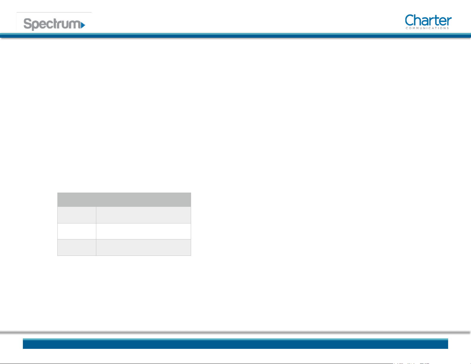
• BASIC MODEM INFORMATION
Example of Cable RF
MAC Address 00:71:CC:8E:54:C7
Firmware Version 14.1.2xxx
Compatibility DOCSIS 3.1/3.0/2.0/1.0 certified Ethernet
10/100/1000 Mbps
Local Web
User Interface
Access
http://192.168.100.1
Modem Web
Page Login (web user
interface)
Login: technician
Password: C0nf1gur3Ubee#
• UNDERSTANDING DEVICE CONNECTIONS
REAR PANEL:
Ethernet (Internet): Connect to an Ethernet-enabled device such as a computer,
gaming console or a wireless access point (LAN switch, router) using an RJ45
Ethernet cable.
Voice 1-2: Use to connect analog telephones to the device. Telephone service
must be enabled by your service provider.
Cable: Use to connect to the coaxial cable from your Internet service provider.

2
Spectrum D3.1 eMTA Quick Installation Guide
Power: Use to connect to the power adapter. Plug the other end into the wall
power outlet.

Spectrum D3.1 eMTA Quick Installation Guide
3
• UNDERSTANDING DEVICE CONNECTIONS • INSTALLATION DIAGRAM (Cont.)
RJ-45
Analog Phones (up to 2)
RJ-11
Connect a PC or Ethernet enabled device
(
wireless switch or router). A
PC should be
connected for initial device installation and
configuration.
Cable/RF

4
Spectrum D3.1 eMTA Quick Installation Guide
FRONT PANEL:
Reset: Use to reset the device settings. When the Reset button icon, and the surrounding ring are illuminated, press and hold the button for 4 seconds to initiate a
power cycle. If the lights are not lit, the device can be factory reset. Press and hold the button for 10 seconds to reset the device to factory default settings. Note:
When the button and ring are lit, a power cycle must be performed prior to performing a factory reset.
• INSTALLING THE MODEM
1. Connect the coaxial cable (not supplied) to the Cable connector on the rear panel
of the modem and connect the other end to the cable wall outlet. Do not bend or
over tighten the cables, as this may strain the connector and cause damage. To
connect a modem and a television to the same wall outlet, you must use a cable
line splitter (not included).
2. Connect the Ethernet cable (supplied) to a Ethernet port on the back panel of the
modem and connect the other end to the Ethernet port of a PC. Use a Category 5e
or Category 6 Ethernet cable with RJ-45 connectors to ensure Gigabit Ethernet
speeds (if the computer supports it).
3. Connect an RJ-11 phone cable (not supplied) to the Voice 1 or 2 port on the
modem (when provisioned for voice service as specified by the service provider),
and connect the other end to the phone port of the telephone. If voice service is
not provisioned through the service provider, telephone service is not available.
4. Connect the power adapter (supplied) to the Power port on the modem. Connect
the other end to a power outlet.
5
Spectrum D3.1 eMTA Quick Installation Guide
Label Size in Millimeters (mm)
A9.5 +/- 0.2
B3.7 +/- 0.1
C34.5 +/- 0.2

6
Spectrum D3.1 eMTA Quick Installation Guide
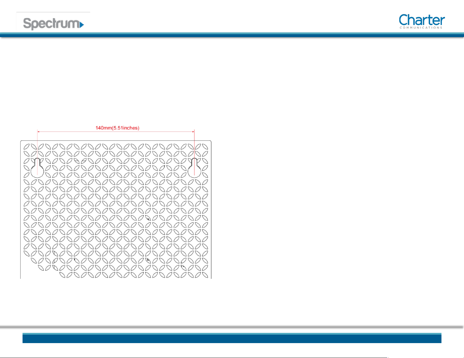
• DEVICE WALL MOUNT INSTRUCTIONS
7
Spectrum D3.1 eMTA Quick Installation Guide
You can mount the Spectrum D3.1 eMTA on a wall using the 2 mounting brackets
on the side of the device. Two round or pan head screws are recommended. See
the figure below for measurements.
To mount the device on a wall:
1. Install the 2 screws horizontally on the wall 140 mm (5.51 inches) apart.
Note: The screws should protrude from the wall so you can fit the device
between the head of the screws and the wall. If you install the screws in
drywall, use hollow wall anchors to ensure the unit does not pull away from
the wall due to prolonged strain from the cable and power connectors.
2. Mount the device on the wall
NOTE to CATV SYSTEM INSTALLER:
This reminder is provided to call the CATV systems installer's attention to section 820-93 of
the National Electric Code, which provides guidelines for proper grounding and in
particular, specify that the Coaxial cable shield shall be connected to grounding system of
the building, as close to the point of cable entry as practical.
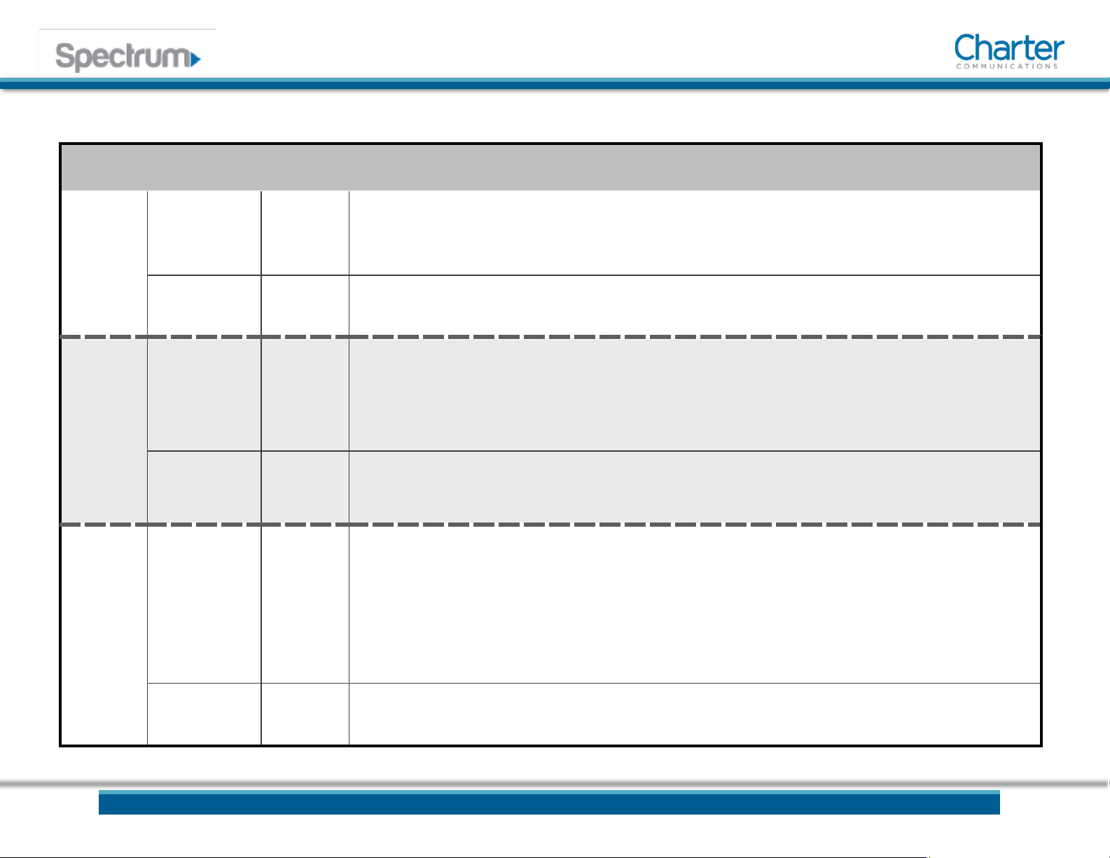
•LED BEHAVIOR
8
Spectrum D3.1 eMTA Quick Installation Guide
LED COLOR DESCRIPTION
Power
Status Light BLUE
•Powering Up: Flashing between On Blue and Off
•Normal Operation: On Blue
•Network Access Denied: If receiving power, On Blue
Illuminated
Text WHITE • Powering Up and Fully Powered: On White
Online
Status Light BLUE /
WHITE
•Determining Connection: Pulsing between On Blue and On White
•Device has entered DOCSIS 3.0 Bonded State: On White
•Device has entered DOCSIS 3.1 Bonded State: On Blue
•Determining Connection: Pulsing between On Blue and On White
Illuminated
Text WHITE •Determining Connection: On White
•Connected: On White
Voice
Status Light BLUE
•Voice Service Not Provisioned: Off
•Voice Service Active: On Blue
•Phone Cable Connected to Voice Port: On Blue
•Phone Cable Not Connected to Voice Port: On Blue
•Any Phone Off-Hook: Pulsing between On Blue and Off
•Unable to Establish Phone Connection: Off
Illuminated
Text WHITE • Voice Service Active: On White
9
Spectrum D3.1 eMTA Quick Installation Guide
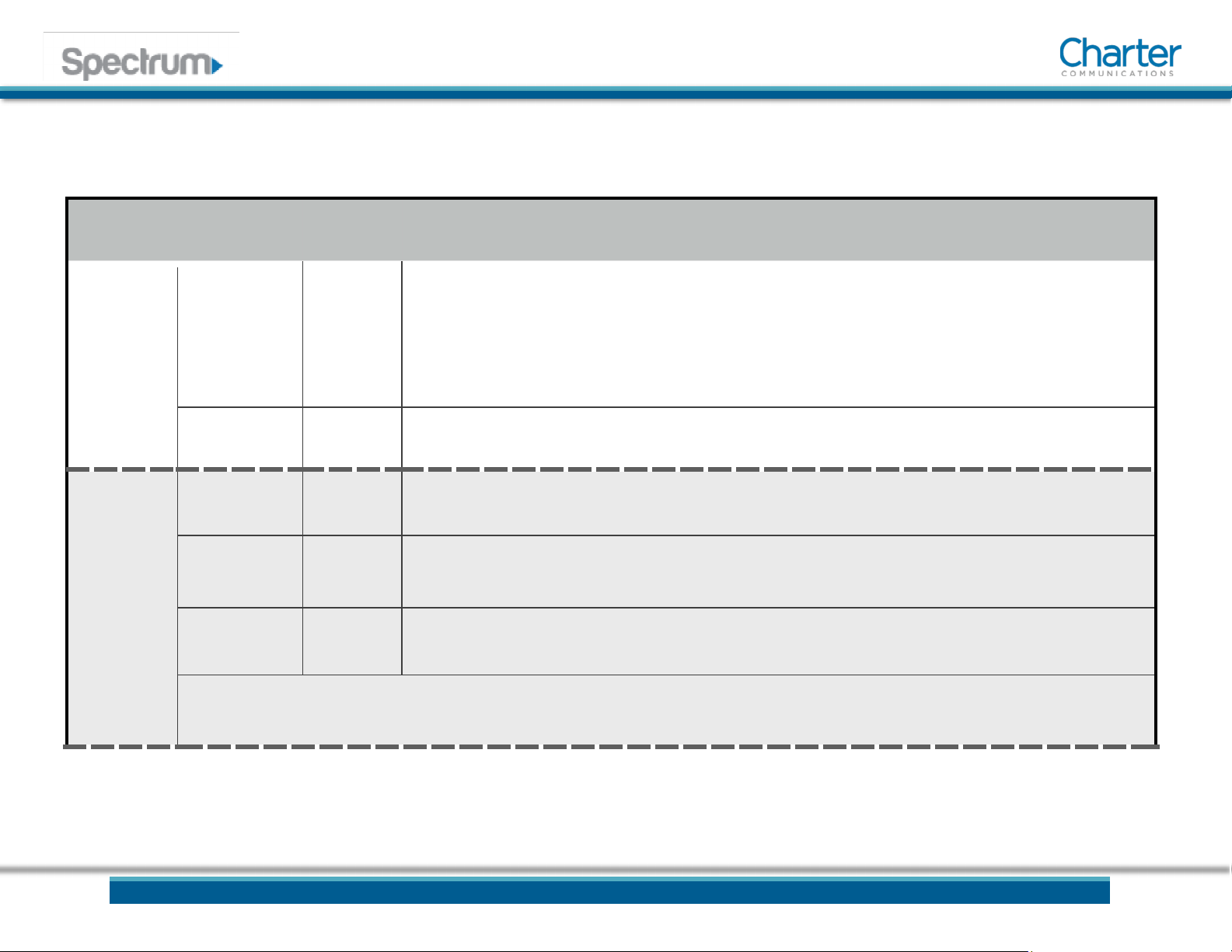
•LED BEHAVIOR (Cont.)
LED COLOR DESCRIPTION
Battery
(NOTE:
Battery is
optional)
Status Light BLUE / RED
•Battery at 21% (of usable charge) or Higher: On Blue
•Battery at 20% (of usable charge) or Lower: On Red
•Battery at 10% (of usable charge) or Lower: Flashing between On Red and Off • No Battery
Installed: Off
•Battery Charging: Pulsing between On Blue and Off
Illuminated Text
WHITE • Battery Installed: On White
Reset
Button Icon
Light WHITE
•Device is in a State that Suggests a Power Cycle: On White
•Device is NOT in a State that Suggests a Power Cycle: Off
Ring RED •Device is waiting to be Power Cycled: Pulsing between On Red and Off
•Device is NOT in a State that Suggests a Power Cycle: Off
Illuminated Text
WHITE • Device is in a State that Suggests a Power Cycle, or is waiting to be Power Cycled: On White
Note: When the device is in a state that suggests a power cycle (the button icon and the surrounding ring are lit), a factory reset cannot be
performed. The user must power cycle the device, then perform a factory reset.
10
Spectrum D3.1 eMTA Quick Installation Guide
Ethernet Status
Lights
GREEN /
ORANGE
•An Ethernet Device is Connected at 100 Mbps Speeds: On Green
•An Ethernet Device is Connected at 1000 Mbps Speeds (Gigabit Ethernet): On Orange
•An Ethernet Device is Connected at 10 Mbps Speeds: Off
•Data is Being Passed Between the Spectrum D3.1 eMTA and the Connected Device: Flashing Green or
Orange

Spectrum D3.1 eMTA Quick Installation Guide
•
Table of contents
Other Charter Modem manuals


Popular Modem manuals by other brands


Javad
Javad HPT104BT Series Operator's manual

NETGEAR
NETGEAR Nighthawk R7100LG manual

Intellisystem
Intellisystem IT-7304-PC user manual

Gongjin Electronics
Gongjin Electronics MG7540 user manual

Silex technology
Silex technology SX-10WAG user manual

Presto
Presto DSL Series Installation, operation and service manual