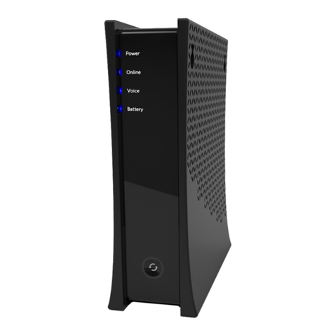
Charter Spectrum E31U2V1 User manual

E31U2V1
Charter
C'OHM
Nl
ATION
DOCSIS
3.1
Advanced
Voice
Modem
Quick
Installation
Guide
Spectru~

E31U2V1
Quick
Installation
Gu
ide
•
SAFETY
NOTICES
DeviC-e
Grounding
:
Install
the
cable
modem
to
•
ncl
ud
e gr
ound1ng
the
coa)(1al
cable
to
the
earth
as
close
as
practical
to
the
building
entrance
per
ANSI/NFPA
70
and
the
National
El
cc
t
ncal
Code
(NEC,
in
part•cular.
Sect
tan
820
93,
Grounding
of
the
Outer
Conduct•ve
Sh1eld
of
a Coax1al
Cable).
The
dev•ce
is
designed
for
IT
power
systems
w1th
phase-to-phase
vol
t
age
at
120V
.
Th1s
umt
~a
100·240V,
50-60Hz
power
adapter.
The
power
adapter
mu
st
be
keyed
for
proper
polanza
t1on,
and
must
be
fully
•nserted
to
contact
the
back
of
the
power
connector
port
to
ensure
sn
ug
connection.
Use
only
the
supphgd
power
adaoter
DlsconnKtlng
the
Device
:
If
the
cable
modem
becomes
damaged
or
encounters
some
other
abnormality,
d1sconnect
the
power
adapter
from
the
AC
wall
outlot
•mmcchatcly.
Temperature
and
Altitude
:
Install
t
he
dev1ce
1n
a
locat1on
not
to
exceed
the
max1mum
opcrat1ng
temperature
of
104
•F
(40
.
C).
Maxtmum
operattng
alt1tude
ts
5000
m
(16,404
ft.).
•
PREPARING
FOR
INSTALLATION
Verify
package
contents.
RF
cable
connecto
r
s,
and
p
ower
out l
et
.
../
Unpack
t
he
box
and
co
nf1rm
the
fo
ll
ow
1
ng
componen
t
s:
I 1
Ethernet
Cable
l
Power
Adapter
E31U2Vl
(RJ-45
_>
____
<
'-
"'"-
only
.....:.-
'"'
-'-
odo<>
__;'-'-
.,
.:.
>_
_.
.f
Locate
the
RF
(coax•al)
cable
connector
on
the
wall
.
../
Venfy
the
power
outlet
IS
wo
r
k.ng
and
ts
w~red
correctly.
Place
your
cable
modem
w1th1n a
proper
distance
from
the
outlet.
Charter
•
BASIC
MODEM
INFORMATION
~~a~:~e
:~;.~~~·
00:71CC8E:54:C7
Firmware
Version
14 2.
XXXX.XX
Compatibil
i
ty
Local
Web
Use
r
Interface
Access
Modem
Web
Page
Login
DOCSIS
3.1/3.0/2.0/1.0
certofied
Ethernet
10/100/1000
Mbps
htlp
://
192.168.100.1
Login
:
technician
Pa
ss
word
:
(use
Secure
Password
of
the
Day)
•
UNDERSTANDING
DEVICE
CONNECTIONS
REAR
PANEL
:
Ethernet
(Internet)
:
Connoc
t
to
an
Ethcrnct-enabled
device
such
as
a
compu
ter,
gam
i
ng
console
or
a w1reless
access
point
(LAN
sw1tch,
rou
t
er)
us
t
ng
an
RJ45
Ethernet
cable.
Voice
1-2
:
Use
to
connect
an
alog
te
l
ephones
to
the
device
Telephone
servtce
mus
t
be
enabled
by
your
scrv1ce
provtdcr
Ca
ble
:
Use
to
connec
t
to
the
coax1al
cable
from
your
Internet
serv1ce
prov1der
Power:
Use
to
connect
to
the
power
adapter
Plug
t
he
ot
her
end
1nto
the
wall
power
outlet

Spectrum.
E31U2V1
Quick
Installation
Guide
•
UNDERSTANDING
DEVICE
CONNECTIONS
(Cont
.)
FRONT
PANEL
:
Reset:
Use
to
reset
the
device
sett1ngs
When
the
Reset
button
icon,
and
the
surrounding
nng
are
1llum•nated,
press
and
hold
the
button
for
o4
seconds
to
initiate
a
power
cycle.
If
the
ltghts
arc
not
l1t,
the
dov1ce
can
be
factory
reset.
Press
and
hold
the
button
for
10
seconds
to
reset
the
dcv•cc
to
factory
default
settings.
Not
e
When
the
bu~ton
and
nng
are
lit,
a
power
cycle
must
be
performed
pnor
to
oerform1nq
a
factory
reset
•
INSTALLING
THE
MODEM
Connect
the
coax1al
cable
(not
supplied)
to
the
Cable
connector
on
the
rear
panel
of
the
modem
and
connect
the
other
end
to
the
cable
wall
outlet.
Do
not
bend
or
over
tighten
the
cables, as th•s
may
stra1n
the
connector
and
cause
damage.
To
connect
e
modem
and
a
television
to
the
same
wall
outlet.
you
must
use
a
cable
hne
sphtter
(not
1
ncluded)
2.
Connect
the
Ethernet
cable
(supphcd)
to
a
Eth
er
n
et
port
on
the
back
panel
of
the
modem
and
connect
the
other
end
to
the
Ethernet
port
of
a PC.
Usc
a
Category
Sc
or
Category
6
Ethernet
cable
w1th
RJ-45
connectors
to
ensure
G1gab1t
Ethernet
speeds
(1f
the
computer
supports
It)
3
Connect
an
RJ-11
phone
cable
(not
supplied)
to
the
Voice
1
or
2
port
on
the
modem
(when
prov1s1oned
for
vo1ce
serv•ce
as
spec1hed
by
the
servtce
provtder),
and
connect
the
other
end
to
the
phone
port
of
the
telephone
If
vo•ce
scrvtce
1s
not
provtstoned
through
the
serv1ce
provtder,
telephone
service
is
not
ava1lable.
4
Connect
the
power
adapter
(supplied)
to
the
Power
port
on
the
modem
Connect
the
other
end
to
a
power
outlet
Charter
•
INSTALLATION
DIAGRAM
E31U2V1
~
03
.1
Advanced
Voice
Gateway
I
AnalogPhones
(up
to
2)
RJ-11
-
CcMict
a
PC
or
Ehmlt
a'rlbllld dlw::e
l~twltdtor,...,)
APCihol.tdbl
oonnedld
b'
.-...
dew::e
nst~~~M~on
n
l
"il
----

SpeclnJtn•
E31U2V1
Quick
Installation
Guide
•
DEVICE
WALL
MOUNT
INSTRUCTIONS
You
can
mount
the
E31U2V1
on
a
wall
ustng
the
2
mountmg
brackets
on
the
stde
of
the
devtce
Two
round
or
pan
head
screws
are
recommended
See
the
figure
below
f
or
measurements.
A B c
$Ia
In
Mlllloi-...
(IIIII\)
A 9.5
..
;.
0 .2
B
3.7
..
;.
0.1
c
34
.5 +
/·
0 .2
To m o
unt
the
device
on
a
wall
:
1.
Install
the
2
screws
hortzontally
on
the
wall
140
mm
(5
.51
•nchcs)
apart
.
Charter
1~
5
5tww::r.)
N
ote
:
The
screws
should
protrude
from
the
wall
so
you
can
ftt
tho
dcvtce
between
the
head
of
the
scr
ews
and
the
wall.
If
you
tnstall
the
screws
.n
drywull,
usc
hollow
wall
anchors
to
ensure
the
unit
does
not
pull
away
fr
om
tho
wall
due
to
prolonged
stra
tn
from
t
he
cable
and
power
connectors
2.
Mount
the
device
on
the
wall
NOTE
to
CATV
SYSTEM
I
NSTAL
LER
:
This
remmder
IS
provK/ed
to
calf
t,.,.
CATV
systems
mstaller's
attentK>n
to
sectiOn
820-93
of
the
NiJttOni!l
E/cctoc
Code.
whiCh
provldfls
gu~fmes
for
proper
groundmg
and
1n
particular.
spcc1fy
th.Jt
thfl
COiJxli!ff CiJble sh1ekJ
shalf
be
connected
to
grounding
system
of
the
/xJ11dmg,
~s
close
to
the
pomt
of
c.,Oie
fHltry
.,s
pra<:tteaf.
11
111
1
11
1
111111
1
1111
1
11
11
1111
540.01320.Q15
-- ------------------------------------------------------ --- 3

Spec~
E31U2V1
Quick
Installatio
n G
uide
Charter
e
LED
BEHAVIOR
LaD
COLOR DIESCRIPI'10N
-• P
owen
ng U
p:
Fla
s
hin
g
be
t
ween
On
Blue
a
nd
Off
Status
Light
BLUE
Normal
Ope
rat1on: O n
Blue
Power
Ne
tw
ork
Access
Denied
:
If
rccctving
power.
On
Blue
Illuminated
WHITE
Powering
Up
and
Fully
Powered:
On
Whit
e
Text
...... ........ ...... .....
.................................................
Determ1
n1
ng
Connect
i
on
: Pulsing
be
t
wee
n
On
Blue
and
On
White
Statu
s
Light
BLUE
/
Device
has
ente
r
ed
DOCSIS
30
Bonded
St
ate:
On
White
WHITE
Dev1ce
has
entered
DOCSIS
3.1
Bonded
State
On
Blu
e
Online
L-
Determ1n1ng
Connect1on
· Pulsing
between
On
Blue
and
On
White
---
----
Illuminated
WHITE
Dete
rmt
ntng
Conncct&on
·
On
White
Text
Connected:
On
White
...... ........ ...... .....
.................................................
•
Voice
Se
r
vice
Not
Prov•s
•
oned:
Off
•
Vo•ce
Sc
rv&cc
Ac
t
ive
: On
Blue
Status
Light
BLUE
•
Phone
Cable
Connected
to
Vo1ce
Port
:
on
Blue
P
hone
Cable
N
ot
Connected
to
Voice
Port:
On
Blue
Vo
ice ·
Any
Phone
Off-
H
ook
:
Pu
ls
ing
between
On
Blue
and
Off
• U
na
bl
e to
Es
tabli
sh
Phone
Con
n
ec
t
io
n:
Off
1-
Il
lum
inat
ed
WHITE
•
Voice
Service
Active:
On
Wh
ite
T
ex
t

Spec~
E31U2V1
Quick
Installation
Guide
Charter
•
LED
BEHAVIOR
(Cont.)
LED
Battery
(
NOTE
:
Battery1
s
o
ptional
)
Reset
Ethernet
I
Status
Light
Ill
u
mina
t
ed
T
ext
COLOR
--
BLUE
/
RED
WHITE
Battery
at
21%
(of
usable
charge)
or
Higher·
On
Blu
e
Battery
at
20%
(of
usable
charge)
or
Lower
: O n
Red
Battery
at
10%
(of
usable
charge)
or
Lower
.
Fl
as
hi
ng
between
On
Red
and
Off
No
Battery
Installed
: O
ff
Battery
Charging:
Pul
s
ing
between
On
Blu
e
and
O
ff
Battery
In
stalled:
On
Whit
e
Button
Icon
WHITE
Dcvoce
os
on
a
State
tha
t
Suggests
a P
ower
Cycle:
On
White
Light
1 I Devoce
os
NOT
on
a
State
that
Suggests
a
Power
Cycle
Off
.
8Devoce
os
wai
t
ing
to
be
Power
Cycle
d:
Pulsing
between
On
R~d
and
Off
Ror19
RED
Devoce
is
NOT
in
a
State
that
Su
gg
ests
a
Po
wer
Cycle:
Off
lllu;'!~:ted
WHITE
~;~
e
is
in
a State
tha
t
Sugges
t s a
Powe
r
Cycle,
or
is
wai
t
ong
to
be
Power
Cycled:
On
Note
:
When
the
d
evice
IS m a
state
t
hat
suggests
a
powe
r
cycle
(the
button
icon
and
the
surroundmg
ring
are
lit),
a
factory
reset
cann
ot
be
performed
.
The
user
must
power
cycle
the
dcvtce
,
then
perform
a
factory
reset
Stat
us
Lights
An
Ethernet
Device
os
Connected
at
100
Mbps
Speeds
:
On
Green
An
Ethernet
Device
os
Connected
at
1000
Mbps
Speeds
(Gogabot
Ethernet):
On
GREEN
/
Or
ORANGE
•
An
Ethernet
Device
is
Co
nn
ected
at
10 M
bps
Speeds
:
Off
•
Data
os
Being
Passed
Between
the
E3
1U2V1
and
t
he
Connected
Devoce:
Flashing
Green
or
mgj

Spect~
E31U2V1
Quick
Installation
Guide
•
FEDERAL
C
OMMUNICATION
COMMISSION
I
NTERFERENCE
ST
ATEMENT
Thts
devtce
complies
w1th
Part
15
of
th
e
FCC
Rules.
Opera
tt
on
•s
subJect
to
the
follow•ng
two
condtttons:
(1)
Thts
device
may
no
t
cause
harmful
Interference.
and
(2)
thts
devtce
must
accept
any
.nterference
rece•ved,
lncl
udt
ng
tnte
rferencc
that
may
cause
undestred
operatton
Thts
equtpment
has
been
tes
t
ed
and
f
ound
to
comply
wtth
the
limtts
for
a
Cbss
B
dtgttal
devtce,
pursuant
to
Part
15
of
the
FCC
Rules.
These
hmets
are
destgned
to
provide
reasonable
protec
t
ton
aga~nst
harmful
tntcrfcrcncc
'"
a
restdcntta
l
tnstalla
t
ton.
This
equtpment
gene
rates,
uses
and
can
ra
diate
radto
freque
ncy
energy
and.
if
not
installed
and
usod
tn
acco
rdan
ce
w1th
the
.nstructtons,
may
cause
harm
f
ul
mt
crfcrcncc
to
rad
io
co
mmun
ications.
However.
there
is
no
guarantee
that
inte
rfer
ence
wdl
not
occ
ur
1n
a
partiCUlar
installatiOn
.
If
thts
cqu1pmc
nt
does
cause
ha
r
mful
mte
rf
cr
cnce
to
radto
or
te
levisio
n
reception,
wh1ch
can
be
de
t
erm•ned
by
turn
t
ng
th
e
cqu
t
pmen
t off
and
on.
t
he
use
r
is
encou
r
aged
to
tr
y
to
co
rr
ec
t
the
Inte
rf
er
ence
by
one
of
th
e
fo
ll
owing
measu
r
es.
Reorient
or
relocate
t
he
rc
cc1vmg
a
nt
en
na
.
Increase
the
separation
betwee
n the
eq
u1pm
cnt
and
r
eceive
r.
Connect
the
equipmen
t
in
to
an
ou
tl
ot
on
a
c1
rc
u1
t
diff
er
ent
from
th
at
to
which
t
he
r
cce1vcr
1s
connec
ted
.
Consult
th
e
deale
r
or
an
expcncnccd
rad
1
o/TV
te
ch
mc
i
an
f
or
help.
FCC
Caution:
Any
changes
or
mod1fica
t1
ons
not
expressly
approved
by
the
party
responsible
for
compliance
could
vo1d
th
e
user's
author
ity
to
operate
th1s
equ1pmcnt
Charter
Th1s t
ran
sm1tter
must
no
t
be
co-loca
t
ed
or
operatmg
1n
conJunctton
wtth
any
other
antenna
or
transmt
tter
Radiation
Exposure
Sta
tem
ent
:
Th1s
equ•pment
complies
wtth
FCC
rad•atton
exposure
hm1ts
set
f
orth
f
or
an
uncon
t
rolled
cnv1r
onment.
Thts
equipment
should
be
.nstalled
and
operated
wtlh
mtmmum
dtstancc
20cm
between
th
e
r
adia
tor
&
your
body
Table of contents
Other Charter Modem manuals
