Chassis Plans ATXP-875P Use and care manual

ATXP-875P
Long Life Industrial Motherboard
Revision A
Technical Reference
Intel®Pentium 4
With Hyper-Threading
Embedded Processors
Intel 875P Chipset

Warranty The product is warranted against material and manufacturing defects for two years from
date of delivery. Buyer agrees that if this product proves defective Chassis Plans is only
obligated to repair, replace or refund the purchase price of this product at Chassis Plans’
discretion. The warranty is void if the product has been subjected to alteration, neglect,
misuse or abuse; if any repairs have been attempted by anyone other than Chassis Plans;
or if failure is caused by accident, acts of God, or other causes beyond the control of
Chassis Plans. Chassis Plans reserves the right to make changes or improvements in any
product without incurring any obligation to similarly alter products previously purchased.
In no event shall Chassis Plans be liable for any defect in hardware or software or loss or
inadequacy of data of any kind, or for any direct, indirect, incidental or consequential
damages arising out of or in connection with the performance or use of the product or
information provided. Chassis Plans’ liability shall in no event exceed the purchase price
of the product purchased hereunder. The foregoing limitation of liability shall be equally
applicable to any service provided by Chassis Plans.
Return Policy Products returned for repair must be accompanied by a Return Material Authorization
(RMA) number, obtained from Chassis Plans prior to return. Freight on all returned items
must be prepaid by the customer, and the customer is responsible for any loss or damage
caused by common carrier in transit. Items will be returned from Chassis Plans via
Ground, unless prior arrangements are made by the customer for an alternative shipping
method.
To obtain an RMA number, call us at (858) 571-4330. We will need the following
information:
Return company address and contact
Model name and model # from the label on the back of the board
Serial number from the label on the back of the board
Description of the failure
An RMA number will be issued. Mark the RMA number clearly on the outside of each
box, include a failure report for each board and return the product(s) to our San Diego,
CA facility:
Chassis Plans
8295 Aero Place
San Diego, CA 92123
Attn: Repair Department

TRADEMARKS IBM, PC/AT, VGA, EGA, OS/2 and PS/2 are trademarks or registered trademarks of
International Business Machines Corp.
Intel is a registered trademark of Intel Corporation.
MS-DOS and Microsoft are registered trademarks of Microsoft Corp.
PICMG, SHB Express and the PICMG logo are registered trademarks of the PCI
Industrial Computer Manufacturers Group.
All other brand and product names may be trademarks or registered trademarks of their
respective companies.
LIABILITY This manual is as complete and factual as possible at the time of printing; however, the
DISCLAIMER information in this manual may have been updated since that time. Chassis Plans reserves
the right to change the functions, features or specifications of their products at any time,
without notice.
Copyright © 2007 by Chassis Plans. All rights reserved.
Web: www.chassisplans.com
Chassis Plans
8295 Aero Place • San Diego, CA 92123
Sales (858) 571-4330 • Fax (858)-571-6146 • Web www.chassisplans.com


ATXP-875P Technical Reference Introduction
Chassis Plans I
Table of Contents
Notice .....................................................................................................................................................III
Introduction.........................................................................................................................................IV
Chapter 1 Pre-Configuration....................................................................................................1
Step 1 Setting the Jumpers.....................................................................................................2
Jumper Locations................................................................................................................................3
CMOS Reset.........................................................................................................................................4
ATA-Disk Connector Voltage Selection............................................................................................4
Audio Jack Output Selection..............................................................................................................4
On-board Ethernet 10/100 (optional 1Gb) Enabling.........................................................................4
Step 2 SDRAM, CPU, and Cables Installation.....................................................................5
ATXP-875P Memory Configuration....................................................................................................5
CPU Installation...................................................................................................................................5
Installing Cables..................................................................................................................................6
Power and Control Panel Cables.......................................................................................................6
Installing Peripheral Cables ...............................................................................................................6
Index of Connectors............................................................................................................................9
Chapter 2 AMIBIOS Setup ......................................................................................................11
Main Setup .........................................................................................................................................14
Advanced BIOS Setup.......................................................................................................................14
PCI/PnP Setup....................................................................................................................................26
Boot Setup .........................................................................................................................................30
Security Setup ...................................................................................................................................32
Chipset Setup ....................................................................................................................................34
Exit Menu............................................................................................................................................37
Chapter 3 Upgrading...............................................................................................................39
Upgrading the Microprocessor........................................................................................................39
Upgrading the System Memory .......................................................................................................39
Appendix A Technical Specifications .................................................................................47
Chipsets..............................................................................................................................................47
BIOS....................................................................................................................................................47
Embedded I/O ....................................................................................................................................47
Industrial Devices..............................................................................................................................50
Miscellaneous....................................................................................................................................50
Mechanical Drawing..........................................................................................................................51
Memory Map.......................................................................................................................................52
DMA Channels ...................................................................................................................................52
I/O Map................................................................................................................................................53
PCI Configuration Space Map..........................................................................................................54
Interrupts............................................................................................................................................54
SMBUS................................................................................................................................................55
PCI Interrupt Routing Map................................................................................................................55
Connectors Pin-out...........................................................................................................................56

Introduction ATXP-875P – Technical Reference
II Chassis Plans
Appendix B Flash BIOS programming and codes.............................................................63
Troubleshooting POST .....................................................................................................................64
Critical Error BEEP Codes................................................................................................................69
Appendix C On-Board Industrial Devices............................................................................70
Post Code Display.............................................................................................................................70
Watchdog Timer ................................................................................................................................70
On-board Ethernet.............................................................................................................................71
Serial Ports.........................................................................................................................................72

ATXP-875P Technical Reference Introduction
Chassis Plans III
Notice
The company reserves the right to revise this publication or to change its contents without notice. Information
contained herein is for reference only and does not constitute a commitment on the part of the manufacturer or any
subsequent vendor. They are in no way responsible for any loss or damage resulting from the use (or misuse) of this
publication.
This publication and any accompanying software may not, in whole or in part, be copied, photocopied, translated or
reduced to any machine readable form without prior consent from the vendor, manufacturer or creators of this
publication, except for copies kept by the user for backup purposes.

Introduction ATXP-875P – Technical Reference
IV Chassis Plans
Introduction
Thank you for your purchase of the ATXP-875P industrial embedded motherboard. The ATXP-875P design was
based on the Intel 875P chipset providing the ideal platform to industrial applications. The ATXP-875P design is
based on the Intel Pentium 4 (mPGA478) processor.
With proper installation and maintenance, your ATXP-875P will provide years of high performance and trouble free
operation.
This manual provides a detailed explanation into the installation and use of the ATXP-875P industrial embedded
motherboard. This manual is written for the novice PC user/installer. However, as with any major computer
component installation, previous experience is helpful and should you not have prior experience, it would be prudent
to have someone assist you in the installation. This manual is broken down into 3 chapters and 3 appendixes.
Chapter 1 - System Board Pre-Configuration
This chapter provides all the necessary information for installing the ATXP-875P. Topics discussed
include: installing the CPU (if necessary), DRAM installation and jumper settings. Connecting all the
cables from the system board to the chassis and peripherals is also explained.
Chapter 2 - BIOS Configuration
This chapter shows the final step in getting your system firmware setup.
Chapter 3 - Upgrading
The ATXP-875P provides a number of expansion options including memory. All aspects of the upgrade
possibilities are covered.
Appendix A - Technical Specifications
A complete listing of all the major technical specifications of the ATXP-875P is provided.
Appendix B - Flash BIOS Programming and Codes
Provides all information necessary to program your AMIBIOS Flash BIOS. POST Codes and beep codes
are described in details.
Appendix C – On-Board Industrial Devices
Two on-board 10/100/1000 (one 10/100 optional) Ethernet controllers (second 10/100/1000 Ethernet
optional), four serial ports (two optional RS422/485), watch dog timer and Post Code Display.

ATXP-875P Technical Reference Introduction
Chassis Plans V
Static Electricity Warning!
The ATXP-875P has been designed as rugged as possible but can still be damaged if jarred sharply or struck.
Handle the motherboard with care.
The ATXP-875P also contains delicate electronic circuits that can be damaged or weakened by static electricity.
Before removing the ATXP-875P from its protective packaging, it is strongly recommended that you use a
grounding wrist strap. The grounding strap will safely discharge any static electricity build up in your body and will
avoid damaging the motherboard. Do not walk across a carpet or linoleum floor with the bare board in hand.
ATXP-875P - An Overview
The ATXP-875P represents the ultimate in industrial embedded motherboard technology. No other system board
available today provides such impressive list of features:
CPU Support
•Supports full series of Intel Pentium 4 (mPGA478 400MHz, 533MHz and 800MHz PSB) processors
featuring Intel Hyper-Threading technology.
Supported Bus Clocks
•400MHz, 533MHz and 800MHz.
Memory
•Four DIMM sockets up to 4GB DDR SDRAM, PC2100 (DDR 266MHz), PC2700 (DDR 333MHz) and
PC3200 (DDR 400MHz) featuring dual channel and dynamic mode. Please, refer to chapter 3 for memory
details.
On-Board I/O
•2 Floppies up to 2.88 MB.
•Dual independent Serial ATA ports with transfer rates up to 150 MB/s per port.
•Dual channel PCI 32-bit EIDE controller – UDMA 66/100 supported. One extra connector (mini-Header 44
pin) in parallel to IDE2 for Solid State IDE disk or any 44 pin IDE device support.
•Four high speed RS-232 serial ports 16 Bytes FIFO (16550). COM_B optional RS-232 IrDA, COM_C and
COM_D optional RS-422/485.
•One Centronics™ compatible bi-directional parallel port. EPP/ECP mode compatible.
•One PS/2 mouse and one PS/2 keyboard connectors.
•Auxiliary Keyboard/Mouse header for front panel access.
•Four Universal Serial Bus connectors, USB 1.1 and USB 2.0 compliant.
•Four 32-bit PCI slots, two PCI-X 64-bit slot and one AGP PRO 8x slot.
•Two RJ45 Ethernet connectors (second 10/100/1000 optional, first optional 10/100/1000).
•Power Button – advanced management support.
•Eight GPIOs in a Header.
•Automatic CPU voltage & temperature monitoring device.
•On-board Buzzer.
•Audio AC97 compliant. Microphone In, Stereo Line In and Out, Auxiliary CD/Audio In.
•On-board POST Display Diagnostics.
ROM BIOS
•American Megatrends AMIBIOS with FLASH ROM.

Introduction ATXP-875P – Technical Reference
VI Chassis Plans
Conventions Used in this Manual
8
Notes - Such as a brief discussion of memory types.
Important Information - such as static warnings, or
very important instructions.
When instructed to enter keyboard keystrokes, the
text will be noted by this graphic.

ATXP-875P Technical Reference Chapter 1: Pre-Configuration
Chassis Plans 1
Special Warranty Note:
Products returned for warranty repair will be inspected for damage caused by
improper installation and misuse as described in the previous section and the
static warning below. Should the board show signs of abuse, the warranty will
become void and the customer will be billed for all repairs and shipping and
handling costs.
Static Warning:
The ATXP-875P contains delicate electronic semiconductors that are highly sensitive
to static electricity. These components, if subjected to a static electricity discharge,
can be weakened thereby reducing the serviceable life of the system board.
BEFORE THE BOARD IS REMOVED FROM ITS PROTECTIVE ANTISTATIC
PACKAGING, TAKE PROPER PRECAUTIONS!
Work on a conductive surface that is connected to ground. Before touching any
electronic device, ground yourself by touching an unpainted metal object or, and
highly recommended, use a grounding strap. Damage from static electricity is not
covered by the warranty.
Chapter 1 Pre-Configuration
This chapter provides all the necessary information for installing the ATXP-875P into a standard PC chassis. Topics
discussed include: installing the CPU (if necessary), DRAM installation and jumper settings.
Handling Precautions
The ATXP-875P has been designed to be as rugged as possible but it can be damaged if dropped, jarred sharply or
struck. Damage may also occur by using excessive force in performing certain installation procedures such as
forcing the system board into the chassis or placing too much torque on a mounting screw.
Take special care when installing or removing the system memory DIMMs. Never force a DIMM into a socket.
Screwdrivers slipping off a screw and scraping the board can break a trace or component leads, rendering the board
unusable. Always handle the ATXP-875P with care.
8

Chapter 1: Pre-Configuration ATXP-875P – Technical Reference
2 Chassis Plans
Special note about operating frequency:
The ATXP-875P has the ability to run at a variety of speeds without the need to
change any crystal, oscillator or jumper.
Step 1 Setting the Jumpers
Your ATXP-875P is equipped with a large number of peripherals. As such, there are a large number of
configuration jumpers on the board. Taken step by step, setting these jumpers is easy. We suggest you review each
section and follow the instructions.
Jumper Types
Jumpers are small copper pins attached to the system board. Covering two pins with a shunt closes the connection
between them. The ATXP-875P examines these jumpers to determine specific configuration information. There are
two different categories of jumpers on the ATXP-875P.
A. Two pin jumpers are used for binary selections such as enable, disable. Instructions for this type of jumper are
open, for no shunt over the pins or closed, when the shunt covers the pins.
B. Three or four pin jumpers are used for multiple selections. Instructions for these jumpers will indicate which two
pins to cover. For example: for JPx2-3 the shunt will be covering pins 2 and 3 leaving pins 1 and 4 exposed.
How to identify pin number 1 on Figure 1-1: Looking to the solder side (The board side without components) of the
PCB (Printed Circuit Board), pin number 1 will have a squared pad J. Other pins will have a circular pad Q. They
are numbered sequentially.
Double row jumpers are numbered alternately, i.e. pin number 2 is in the other row, but in the same column of pin
number 1. Pin number 3 is in the same row of pin 1, but in the next column and so forth.
ATXP-875P Technical Reference Chapter 1: Pre-Configuration
Chassis Plans 3
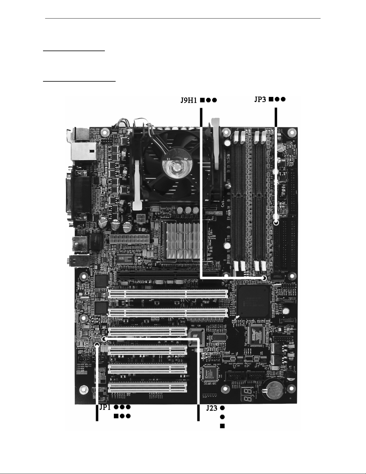
Jumper Locations
Use the diagram below and the tables on the following pages to locate and set the on-board configuration jumpers.
Figure 1-1 Jumper Locations

Chapter 1: Pre-Configuration ATXP-875P – Technical Reference
4 Chassis Plans
CMOS Reset
This option is provided as a convenience for those who need to reset the CMOS registers. It should always be set to
"Normal" for standard operation. If the CMOS needs to be reset, turn off the system, move J9H1 to 2-3, turn the
system on, move jumper to 1-2 and press reset.
Table 1-1 CMOS Reset
Reset CMOS Normal Clear CMOS
J9H1 1-2* 2-3
* Default Settings.
ATA-Disk Connector Voltage Selection
The ATA-Disk Connector J17 can provide either 5Vcc or 3.3Vcc. The jumper JP3 selects the voltage.
Table 1-3 ATA-Disk Connector Voltage Select
ATA-Disk Voltage 5Vcc 3.3Vcc
JP3 1-2* 2-3
* Default Settings.
Audio Jack Output Selection
The audio output on the stacked audio jack connector J12 (green color) can be selected to be stereo line out or stereo
headphone out (amplified signal). The jumper JP1 selects the audio output signals.
Table 1-4 Audio Output Mode Selection
Audio Output Mode Selection Headphone Line Out
JP1 1-3, 2-4 3-5, 4-6*
* Default Settings.
On-board Ethernet 10/100 (optional 1Gb) Enabling
The On-Board Ethernet 10/100 (Intel 82559ER/82551ER, optional 10/100/10000 82540) may be Enabled or
Disabled. The jumper JP23 selects the option.
ATTENTION: Enabling the Ethernet automatically configures the PCI-X bus to regular PCI 32-bit because the PCI
Ethernet controller is connected to PCI-X bus.
Table 1-5 On-Board Ethernet Select
On-Board Ethernet Enabled Disabled
JP23 1-2* 2-3
* Default Settings.
ATXP-875P Technical Reference Chapter 1: Pre-Configuration
Chassis Plans 5
Step 2 SDRAM, CPU, and Cables Installation
Depending upon how your ATXP-875P is configured you may need to install the following:
•SDRAM (DIMMs)
•CPU
ATXP-875P Memory Configuration
The ATXP-875P offers 4 DIMM memory sockets (Locations J6G1, J6G2, J6H1 and J6H2 – Figure 1-3). They can
be configured with 2.5V unbuffered SDRAM DDR modules. It is very important that the quality of the DIMMs is
good. Unreliable operation of the system may result if poor quality DIMMs are used. Always purchase your memory
from a reliable source. Please, refer to chapter 3 for memory details.
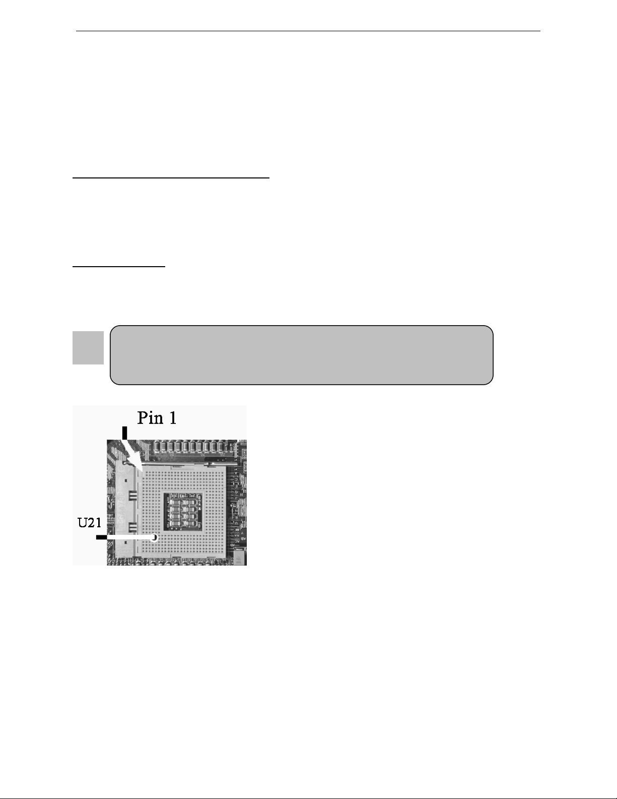
CPU Installation
The ATXP-875P currently supports the following CPUs:
•Full series of Intel Pentium 4 400MHz, 533MHz and 800MHz PSB mPGA478 processors featuring Intel
Hyper-Threading technology.
Locate the CPU socket on your ATXP-875P system board (mPGA478
Socket – Location U21 – Figure 1-4). To install the processor, lift the
lever of the ZIF socket and gently insert the CPU. The CPU will fit
only in the right alignment. Make sure the CPU is inserted all the way.
Lower the lever. Install the CPU fan. Make sure it is locked and
connected to J2F1 (see pin-out in Appendix A).
The continued push of technology to increase performance levels
(higher operating speeds) and packaging density (more transistors) is
aggravating the thermal management of the CPU. As operating
frequencies increase and packaging sizes decreases, the power density
increases and the thermal cooling solution space and airflow become
more constrained. The result is an increased importance on system
design to ensure that thermal design requirements are met for the CPU.
The objective of thermal management is to ensure that the temperature of the processor is maintained within
functional limits. The functional temperature limit is the range within which the electrical circuits can be expected to
meet their specified performance requirements. Operation outside the functional limit can degrade system
performance, cause logic errors or cause component and/or system damage. Temperatures exceeding the maximum
operating limits may result in irreversible changes in the operating characteristics of the component.
If the ATXP-875P industrial embedded motherboard is acquired without the CPU and the thermal solution,
extremely care must be taken to avoid improper thermal management. All Intel thermal solution specifications,
design guidelines and suggestions to the CPU being used must be followed. The ATXP-875P warranty is void if the
thermal management does not comply with Intel requirements.
1. Improper installation of the CPU may cause permanent damage to both the system
board and the CPU. – This is not covered by warranty.
2. Always handle the CPU by the edges, never touch the pins.
3.
A
lwa
y
s use a hea
t
-
s
ink and a CPU
f
an.

Chapter 1: Pre-Configuration ATXP-875P – Technical Reference
6 Chassis Plans
Designing for thermal performance
In designing for thermal performance, the goal is to keep the processor within the operational thermal specifications.
The inability to do so will shorten the life of the processor.
Fan Heatsink
An active fan heatsink can be employed as a mechanism for cooling the Intel processors. This is the acceptable
solution for most chassis. Adequate clearance must be provided around the fan heatsink to ensure unimpeded air
flow for proper cooling.
Airflow management
It is important to manage the velocity, quantity and direction of air that flows within the system (and how it flows)
to maximize the volume of air that flows over the processor.
Thermal interface management
To optimize the heatsink design for the Pentium 4 processor, it is important to understand the impact of factors
related to the interface between the processor and the heatsink base. Specifically, the bond line thickness, interface
material area, and interface material thermal conductivity should be managed to realize the most effective thermal
solution.
Once used, the thermal interface should be discarded and a new one installed. Never assemble the heatsink with a
previously used thermal interface.
This completes the installation of the CPU. Now is it a good time to double check both the CPU and DIMM
installation to make sure that these devices have been properly installed.
Installing Cables
Power and Control Panel Cables
The ATXP-875P gets power from the power connectors J15 and J16 (Figure 1-4). Use only ATX12V-compliant
power supplies with the board. ATX12V power supplies have an additional power lead that provides required
supplemental power for the processor. Always connect the 20-pin and 4-pin leads of ATX12V power supply to the
corresponding connectors, otherwise the board will not boot. Do not use a standard ATX power supply. The board
will not boot with a standard ATX power supply.
Installing Peripheral Cables
Now it is a good time to install the internal peripherals such as floppy and hard disk drives. Do not connect the
power cable to these peripherals, as it is easier to attach the bulky ribbon cables before the smaller power
connectors. If you are installing more than one IDE drive double check your master/slave jumpers on the drives.
Review the information supplied with your drive for more information on this subject.
Connect the floppy cable (not included) to the system board. Then connect remaining ends of the ribbon cable to the
appropriate peripherals. Finally, connect the IDE cable (not included) to the system. If using a Solid State Device,
connect it to the mini-ATA connector. Then connect remaining ends of the ribbon cable to the appropriate
peripherals. This concludes the hardware installation of your ATXP-875P system. Now it is a good time to re-check
all of the cable connections to make sure they are correct.
The connector hole layouts on the ATXP-875P I/O Gasket (optional) are designed according to Intel ATX
specifications.

ATXP-875P Technical Reference Chapter 1: Pre-Configuration
Chassis Plans 7
Figure 1-3 ATXP-875P I/O Gasket
Chapter 1: Pre-Configuration ATXP-875P – Technical Reference
8 Chassis Plans
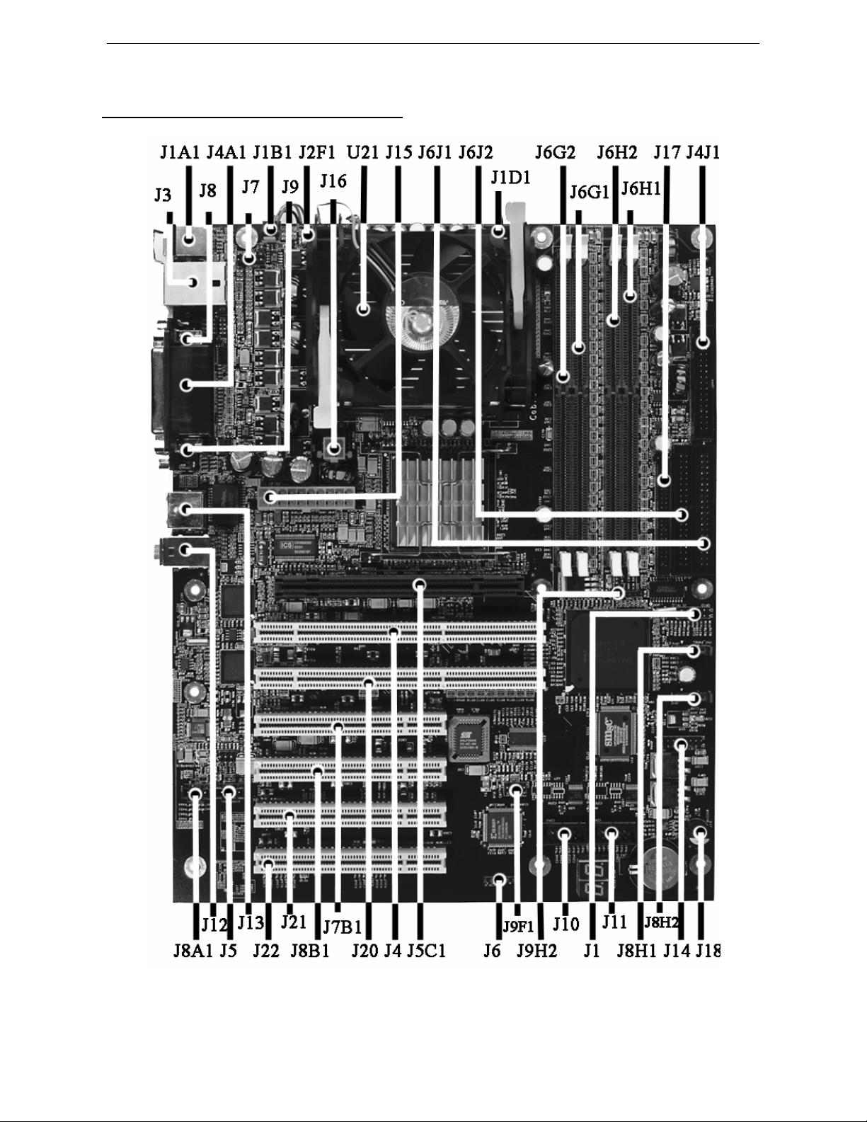
Figure 1-4 Location of Components and Connector

ATXP-875P Technical Reference Chapter 1: Pre-Configuration
Chassis Plans 9
Connector Index
Please refer to Appendix A for pin-out descriptions.
Table 1-6 Connectors description
Connector Description
J1 GPIO Header
J1A1 (Bottom)Keyboard – PS/2 (Top)Mouse – PS/2
J1B1 Rear Chassis Fan
J1D1 ITP
J2F1 CPU Fan
J3 (Bottom) USB (Ports 0 & 1) - (Top) Ethernet 1 (Optional 1Gb)
J4 PCI-X Slot 1
J4A1 LPT - Parallel
J4J1 Floppy Disk Drive Connector
J5 Audio - Aux. In Header
J5C1 AGP PRO Slot
J6 JTAG
J6G1 DDR Channel A DIMM Socket 1
J6G2 DDR Channel A DIMM Socket 0
J6H1 DDR Channel B DIMM Socket 1
J6H2 DDR Channel B DIMM Socket 0
J6J1 Primary IDE
J6J2 Secondary IDE
J7 Keyboard/Mouse Header
J7B1 PCI Slot 1
J8 SER A
J8A1 Audio – CD In Header
J8B1 PCI Slot 2
J8H1 SATA 1
J8H1 SATA 1
J9 SER B
J9F1 USB Header (Ports 2 & 3)
J9H2 Intruder detection Header
J10 SER C
J11 SER D
J12 Audio – Mic. In (pink), Line Out/Headphone (green) and Line In (blue)
J13 Ethernet 2 10/100/1000 (Optional) RJ45
J14 Front Panel Header
J15 ATX Power Connector
J16 ATX Power Aux. Connector
J17 Alt. Secondary IDE
J18 Buzzer/Speaker Alt. Connector
J20 PCI-X Slot 2
J21 PCI Slot 3
J22 PCI Slot 4
U21 CPU Socket

Chapter 1: Pre-Configuration ATXP-875P – Technical Reference
10 Chassis Plans
User's Notes:
Table of contents
Other Chassis Plans Motherboard manuals

Chassis Plans
Chassis Plans MX8 Use and care manual

Chassis Plans
Chassis Plans JXT6966 Use and care manual

Chassis Plans
Chassis Plans ATXP-945G Use and care manual

Chassis Plans
Chassis Plans ATXP-965Q Use and care manual

Chassis Plans
Chassis Plans ATXR-QZ45Q Use and care manual

Chassis Plans
Chassis Plans MTXP-945G Use and care manual

Chassis Plans
Chassis Plans ATXN-5520 Use and care manual


