Chassis Plans ATXP-965Q Use and care manual

ATXP-965Q
Long Life Industrial Motherboard
Revision A
Technical Reference
Intel® Core 2 Duo E6400
Intel® Core 2 Duo E4300
Intel® Pentium 4
or
Intel® Celeron D 440
Embedded Processors
Intel 965Q Express Chipset

Warranty The product is warranted against material and manufacturing defects for two
years from date of delivery. Buyer agrees that if this product proves defective
Chassis Plans is only obligated to repair, replace or refund the purchase price of
this product at Chassis Plans’ discretion. The warranty is void if the product has
been subjected to alteration, neglect, misuse or abuse; if any repairs have been
attempted by anyone other than Chassis Plans; or if failure is caused by
accident, acts of God, or other causes beyond the control of Chassis Plans.
Chassis Plans reserves the right to make changes or improvements in any
product without incurring any obligation to similarly alter products previously
purchased.
In no event shall Chassis Plans be liable for any defect in hardware or software
or loss or inadequacy of data of any kind, or for any direct, indirect, incidental or
consequential damages arising out of or in connection with the performance or
use of the product or information provided. Chassis Plans’ liability shall in no
event exceed the purchase price of the product purchased hereunder. The
foregoing limitation of liability shall be equally applicable to any service provided
by Chassis Plans.
Return Policy Products returned for repair must be accompanied by a Return Material
Authorization (RMA) number, obtained from Chassis Plans prior to return. Freight
on all returned items must be prepaid by the customer, and the customer is
responsible for any loss or damage caused by common carrier in transit. Items
will be returned from Chassis Plans via Ground, unless prior arrangements are
made by the customer for an alternative shipping method.
To obtain an RMA number, call us at (858) 571-4330. We will need the following
information:
Return company address and contact
Model name and model # from the label on the back of the board
Serial number from the label on the back of the board
Description of the failure
An RMA number will be issued. Mark the RMA number clearly on the outside of
each box, include a failure report for each board and return the product(s) to our
San Diego, CA facility:
Chassis Plans
8295 Aero Place
San Diego, CA 92123
Attn: Repair Department

TRADEMARKS IBM, PC/AT, VGA, EGA, OS/2 and PS/2 are trademarks or registered
trademarks of International Business Machines Corp.
Intel is a registered trademark of Intel Corporation.
MS-DOS and Microsoft are registered trademarks of Microsoft Corp.
PICMG, SHB Express and the PICMG logo are registered trademarks of the PCI
Industrial Computer Manufacturers Group.
All other brand and product names may be trademarks or registered trademarks
of their respective companies.
LIABILITY This manual is as complete and factual as possible at the time of printing;
DISCLAIMER however, the information in this manual may have been updated since that time.
Chassis Plans reserves the right to change the functions, features or
specifications of their products at any time, without notice.
Copyright © 2008 by Chassis Plans. All rights reserved.
E-mail: Support@chassisplans.com
Web: www.chassisplans.com
Chassis Plans
8295 Aero Place • San Diego, CA 92123
Sales (858) 571-4330 • Fax (858-571-6146 • Web www.chassisplans.com


ATXP-965Q Technical Reference Index
Chassis Plans i
Table of Contents
PREFACE......................................................................................................................1
ATXP-965Q Top View..........................................................................................................................1
SAFETY PRECAUTIONS WARNING! ...........................................................................2
Static Electricity Warning!.....................................................................................................................2
FCC Notice...........................................................................................................................................2
CE Notice .............................................................................................................................................2
Conventions Used in this Manual.........................................................................................................2
CHAPTER 1TECHNICAL SPECIFICATIONS............................................................3
Embedded Processor (775 LGA package) ..........................................................................................3
Non-Embedded Processors.................................................................................................................3
Chipset .................................................................................................................................................3
Peripheral Chips...................................................................................................................................4
System Memory....................................................................................................................................5
BIOS.....................................................................................................................................................5
Embedded I/0.......................................................................................................................................5
Miscellaneous.......................................................................................................................................6
Power connectors.................................................................................................................................6
Fan Headers.........................................................................................................................................6
TPM header..........................................................................................................................................6
SPDIF OUT header..............................................................................................................................6
Legacy PWR LED Header....................................................................................................................6
Form Factor and Dimensions...............................................................................................................6
Reliability..............................................................................................................................................7
Agency Approvals.................................................................................................................................7
Environmental Requirements...............................................................................................................7
CHAPTER 2 HARDWARE CONFIGURATION...........................................................9
Handling Precautions ...........................................................................................................................9
Connector Location ............................................................................................................................10
Header and Jumper Location.............................................................................................................11
Setting the Jumpers............................................................................................................................13
Jumper Location.................................................................................................................................14
Installing Memory ...............................................................................................................................15
Installing CPU.....................................................................................................................................16
Installing FAN(s).................................................................................................................................18
Installing Power Cables......................................................................................................................19
Back Panel Connections....................................................................................................................20
Header Connections...........................................................................................................................21
Front Panel Header Connections.......................................................................................................25
PCI Express and PCI Slot ..................................................................................................................26
CHAPTER 3 AMIBIOS SETUP.................................................................................27
Starting BIOS Setup...........................................................................................................................27
BIOS Setup Main Menu......................................................................................................................27
Main Setup .........................................................................................................................................30
BIOS SETUP UTILITY .......................................................................................................................30
Advanced BIOS Setup .......................................................................................................................31
BIOS SETUP UTILITY .......................................................................................................................31
Advanced ACPI Configuration............................................................................................................34
Chipset ACPI Configuration ...............................................................................................................34
PCI/PnP Setup ...................................................................................................................................37
Plug and Play O/S..............................................................................................................................38

Index ATXP-965Q Technical Reference
ii Chassis Plans
Palette Snooping................................................................................................................................38
PCI IDE Bus Master ...........................................................................................................................38
Off Board PCI/ISA IDE Card ..............................................................................................................38
Reserved Memory Size......................................................................................................................39
Reserved Memory Address................................................................................................................39
Boot Setup..........................................................................................................................................39
Quick Boot..........................................................................................................................................40
Quiet Boot...........................................................................................................................................40
Add-On ROM Display Mode...............................................................................................................40
Boot up Num-Lock..............................................................................................................................40
PS/2 Mouse Support ..........................................................................................................................40
Wait for ‘F1’ If Error ............................................................................................................................40
Hit ‘DEL’ Message Display.................................................................................................................41
Security Setup....................................................................................................................................42
Chipset Setup.....................................................................................................................................44
Exit Menu............................................................................................................................................45
APPENDIX A TECHNICAL SUMMARY .................................................................47
Block Diagram....................................................................................................................................47
System Memory Map..........................................................................................................................48
DMA Channels ...................................................................................................................................48
I/O Map...............................................................................................................................................49
PCI Routing Table..............................................................................................................................49
PCI Configuration Map.......................................................................................................................50
Interrupt Map......................................................................................................................................51
On-Board Industrial Devices ..............................................................................................................52
Graphics Features..............................................................................................................................53
APPENDIX BRAID CONFIGURATION..................................................................55
Configuring for RAID (Intel Matrix Storage Technology)....................................................................55
Configuring the BIOS for Intel Matrix Storage Technology................................................................55
Creating your RAID Set......................................................................................................................55
Loading the Intel Matrix Storage Technology RAID Driver ................................................................55
APPENDIX C PIN-OUTS ........................................................................................57
COM1.................................................................................................................................................57
COM2.................................................................................................................................................57
COM3.................................................................................................................................................58
COM4.................................................................................................................................................58
IrDA Header........................................................................................................................................59
Universal Serial Bus Header..............................................................................................................59
VGA Connector ..................................................................................................................................60
Serial ATA Connector.........................................................................................................................60
Floppy Disk Drive Header ..................................................................................................................61
Printer Port Header.............................................................................................................................62
ATX Power Connector........................................................................................................................62
CD-IN AUX CD-IN Connectors...........................................................................................................63
FP_HDR (Front Panel Header)..........................................................................................................64
SPI CON (J16)....................................................................................................................................64
APPENDIX D FLASH BIOS PROGRAMMING AND CODES ................................65
How to Reflash the BIOS ...................................................................................................................65
Troubleshooting POST.......................................................................................................................65
Critical Error BEEP Codes .................................................................................................................71
Boot Block Beep Codes .....................................................................................................................71
POST BIOS Beep Codes...................................................................................................................71
Troubleshooting POST BIOS Beep Codes........................................................................................72

ATXP-965Q Technical Reference Index
Chassis Plans iii
Revision History
Revision Revision History Date
01 First Release 10/12/07
02 Updated lay-out and technical information 01/07/08
Notice
The company reserves the right to revise this publication or to change its contents without notice.
Information contained herein is for reference only and does not constitute a commitment on the part
of the manufacturer or any subsequent vendor. They are in no way responsible for any loss or
damage resulting from the use (or misuse) of this publication.
This publication and any accompanying software may not, in whole or in part, be copied,
photocopied, translated or reduced to any machine readable form without prior consent from the
vendor, manufacturer or creators of this publication, except for copies kept by the user for backup
purposes.
Brand and product names mentioned in this publication may or may not be copyrights and/or
registered trademarks of their respective companies. They are mentioned for identification purposes
only and are not intended as an endorsement of that product or its manufacturer.
©January, 2008

Index ATXP-965Q Technical Reference
iv Chassis Plans
This Page Intentionally Blank
ATXP-965Q Technical Reference Preface
Chassis Plans 1
Preface
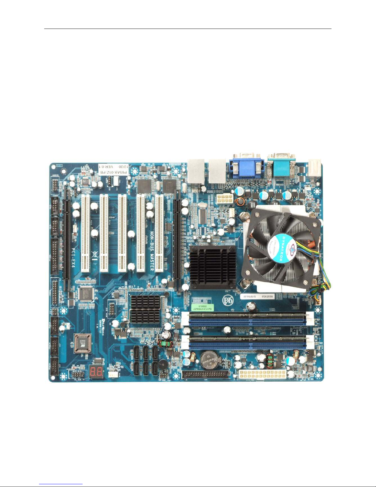
Thank you for your purchase of the ATXP-965Q industrial embedded motherboard. The ATXP-965Q
design is based on the Intel® Q965 Express chipset providing the ideal platform for industrial
applications. The ATXP-965Q will accommodate an Intel Pentium 4, Celeron D 440, or Core 2 Duo
E6400 and E4300 processors in a LGA775 socket (FC-LGA4). With proper installation and
maintenance, your ATXP-965Q will provide years of high performance and trouble free operation.
This manual provides a detailed explanation into the installation and use of the ATXP-965Q industrial
embedded motherboard. This manual is written for the novice PC user/installer. However, as with
any major computer component installation, previous experience is helpful and should you not have
prior experience, it would be prudent to have someone assist you in the installation.
ATXP-965Q Top View

Preface ATXP-965Q Technical Reference
2 Chassis Plans
Safety Precautions Warning!
Static Electricity Warning!
The ATXP-965Q has been designed as rugged as possible but can still be damaged if jarred sharply
or struck. Handle the motherboard with care.
The ATXP-965Q also contains delicate electronic circuits that can be damaged or weakened by
static electricity. Before removing the ATXP-965Q from its protective packaging, it is strongly
recommended that you use a grounding wrist strap. The grounding strap will safely discharge any
static electricity build up in your body and will avoid damaging the motherboard. Do not walk across
a carpet or linoleum floor with the bare board in hand.
FCC Notice
This equipment has been tested and found to comply with the limits for a Class B digital device,
pursuant to part 15 of the FCC Rules. These limits are designed to provide reasonable protection
against harmful interference when the equipment is operated in a commercial environment. This
equipment generates, uses, and can radiate radio frequency energy and, if not installed and used in
accordance with the instruction manual, may cause harmful interference to radio communications.
Operation of this equipment in a residential area is likely to cause harmful interference in which case
the user will be required to correct the interference.
You are cautioned that any change or modifications to the equipment not expressly approve by the
party responsible for compliance could void your authority to operate such equipment.
CE Notice
This is a CE approved product. In a domestic environment this product may cause radio interference
in which case the user may be required to take adequate measures.
Conventions Used in this Manual
8
Notes - Such as a brief discussion of memory types.
Important Information - such as static warnings, or
very important instructions.
When instructed to enter keyboard keystrokes, the
text will be noted by this graphic.
ATXP-965Q Technical Reference Chapter 1 – Technical Specifications
Chassis Plans 3
Chapter 1 Technical Specifications
The ATXP-965Q is a long-life industrial motherboard with multi-core processor technology and PCI
Express support. Powered by the Intel® Q965 Express chipset, the ATXP-965Q motherboard was
designed specifically for performance intensive embedded applications such as Medical, Security,
Imaging, Industrial Automation, and Manufacturing.
Embedded Processor (775 LGA package)
Intel® Pentium® 4 651 2 MB L2 cache, 800 MHz FSB, 65nm
Intel® Celeron® D 352 512K L2 cache, 533 MHz FSB, 65nm
Intel® Core™ 2 Duo E6400 2M unified cache, 800/ 1066 MHz FSB, 65nm
Intel® Core™ 2 Duo E4300 2M unified cache, 800 MHz FSB, 65nm
Intel® Core™ 2 Duo E2160 2M unified cache, 800 MHz FSB, 65nm
Intel® Celeron 440 512K unified, 800 MHz FSB, 65nm
Non-Embedded Processors
Additional supported processors, please contact your Sales Representative.
Chipset
Q965 GMCH Intel® Pentium 4 , Celeron D (Cedar Mill), Core 2
Duo and Conroe L support
Supports FSB of 533/800/1066 MHz
Intel® Integrated Graphics Accelerator 3000
(GMA3000) with CRT and 2 Ch. SDVO(signals
mixed with PCI-E x16)
Analog video maximum resolution
2048x1536@75 Hz refresh
Single dedicated graphics 1 x 16 PCI –E Slot
Two independent channels of DDR2 memory @
533/667/800MHz (4 Slots, 8GB max memory
size)
ACPI 1.0 Power Management
1226 BGA package

Chapter 1 – Technical Specifications ATXP-965Q Technical Reference
4 Chassis Plans
ICH8DO 10Gb/s each direction, full duplex DMI (Direct
Media Interface – between ICH8 and GMCH)
PCI –E V 1.1 root ports
PCI Rev 2.3 @ 33MHz
6 SATA @ 300Gb/s (300MB/s) with integrated
AHCI (Advanced Host Controller Interface)
controller
Intel® RAID Storage Technology supports RAID
0/1/5/10
Audio CODEC support for HD Audio (Std Audio
on I/O Connector; HD Audio on header)
5 UHCI USB 2.0 Host Controllers – 10 external
ports
ACPI 3.0 Support
652 mBGA package
Peripheral Chips
SMSC SCH3114 SIO chip Four full handshake COM ports
IRDA on 6 pin header
Floppy / parallel/ keyboard-mouse
Hardware voltage monitor /CPU temp. monitor
Watchdog timer
PWM fan control outputs / tachometer inputs
Monitors thermal diode of CPU
128-pin VTQFP package
2x PCI-E Gigabit Ethernet controller Intel ® 82573L
10/100/1000 Mbps full and half duplex operation
PCI-E x 1 interface
Full gigabit support at wire speed
Watchdog timer
PWM fan control outputs / tachometer inputs
Monitors thermal diode of CPU
128-pin VTQFP package
Intel ® 82573L
POST Code
(On-board POST code display for self-
diagnostics)
2 seven segment, alphanumeric displays

ATXP-965Q Technical Reference Chapter 1 – Technical Specifications
Chassis Plans 5
System Memory
Four 240-pin DDR2 DIMM sockets
Support for DDR2 800/667/533 MHz DIMMs
Support for up to 8GB of system memory using DDR2 667 or DDR2 533 DIMMs
Support for up to 4GB of system memory using DDR2 800 DIMMs
BIOS
AMI BIOS Firmware Hub (FWH or SPI)
Embedded I/0
Floppy Up to two floppy disk drives
Sizes supported are: 5.25” 360K and 1.2MB; 3.5”
720K, 1.44MB and 2.88MB
Serial Ports (4) 4 full function RS232 serial ports
Shared infrared support (IRDA 1.0 Compliant) on
COM2
Two (2) additional serial ports on 2 10 pin
shrouded headers
6-pin IRDA header
USB Interfaces (10) 4 USB ports on 2 shared RJ45 / Doubled stacked
connectors
6 USB ports on 3x 10-pin headers
Parallel Port (1) One bidirectional and ECP/EPP compatible
parallel port header
Keyboard/Mouse Port Dual stacked PS/2 compatible 6 pin mini-DIN
connector on I/O back-panel
PCI Interfaces / PCI-E Interfaces 1 PCI Express 1x16 dedicated graphics slot
5 PCI Rev.2.3 (5V) bus interface slots (One slot is
non-Bus master)
1 PCI Express 1x4 interface in x16 connector
Video Support DB-15 VGA connector on I/O back-panel
(Maximum resolution 2048x1536 @75Hz)

Chapter 1 – Technical Specifications ATXP-965Q Technical Reference
6 Chassis Plans
Audio Realtek ALC883 HD Audio CODEC
Microphone IN, Stereo LINE OUT, Stereo LINE IN
jacks on I/O back-panel
10-pin HD Audio header for extra surround sound
outputs.
AUX CD-IN (ATAPI), CD-IN (ATAPI) headers
4-pin SPDIF OUT header
Miscellaneous
CMOS/Battery RTC integrated in ICH8 with lithium battery
socket
CR2032 coin battery or equivalent
Front Panel Header Reset, Soft Power, LEDs for power and HDD
CPU Socket 775 – pin LGA
Power connectors
ATX2.2 – 24 pin power connector, backwards compatible with 20 pin
8 pin ATX12V power connector backward compatible with 4 pin.
Fan Headers
CPU – 4 pin header
System fan, NB fan– 4 pin headers supports tachometer monitoring / PWM control
TPM header
Pin out matches available TPM modules (optional)
SPDIF OUT header
4-pin header connected to ALC883 HD audio codec
Pin out compatible with 3rd party SPDIF motherboard cables
Legacy PWR LED Header
3-pin header connected directly to +5V with current limiting resistor.
Form Factor and Dimensions
ATX– 12.0”X 9.6”

ATXP-965Q Technical Reference Chapter 1 – Technical Specifications
Chassis Plans 7
Reliability
MTBF: At 35°C = 206,853
MTBF: At 55°C = 90,296
Agency Approvals
FCC/CE Certification (Please contact your local Regional Sales Manager for the certificate)
Environmental Requirements
RoHS compliant assembly.
CATEGORY OPERATING NON-OPERATING
TEMPERATURE 0°C to 55°C -40°C to 70°C
HUMIDITY 5 to 95% @ 40°C non-condensing 5 to 95% @ 40°C non-
condensing
SHOCK 2.5G @ 10ms 10G @ 10ms
VIBRATION 0.25 @ 5-100Hz 5 @ 5-100Hz

Chapter 1 – Technical Specifications ATXP-965Q Technical Reference
8 Chassis Plans
This Page Intentionally Blank

ATXP-965Q Technical Reference Chapter 2 – Hardware Configuration
Chassis Plans 9
Special Warranty Note:
Products returned for warranty repair will be inspected for damage caused by
improper installation and misuse as described in the previous section and the static
warning below. Should the board show signs of abuse, the warranty will become void
and the customer will be billed for all repairs and shipping and handling costs.
Chapter 2 Hardw are Configuration
This chapter provides all the necessary information for installing the ATXP-965Q into a standard PC
chassis. Topics discussed include: installing the processor, DRAM and jumper settings.
Handling Precautions
The ATXP-965Q has been designed to be as rugged as possible but it can be damaged if dropped,
jarred sharply or struck. Damage may also occur by using excessive force in performing certain
installation procedures such as forcing the system board into the chassis or placing too much torque
on a mounting screw.
Take special care when installing or removing the system memory DIMMs. Never force a DIMM into
a socket. Screwdrivers slipping off a screw and scraping the board can break a trace or component
leads, rendering the board unusable. Always handle the ATXP-965Q with care.
Static Warning
The ATXP-965Q contains delicate electronic semiconductors that are highly sensitive to static
electricity. These components, if subjected to a static electricity discharge, can be weakened thereby
reducing the serviceable life of the system board. BEFORE THE BOARD IS REMOVED FROM ITS
PROTECTIVE ANTISTATIC PACKAGING, TAKE PROPER PRECAUTIONS! Work on a conductive
surface that is connected to the ground. Before touching any electronic device, ground yourself by
touching an unpainted metal object or, and highly recommended, use a grounding strap.
Chapter 2 – Hardware Configuration ATXP-965Q Technical Reference
10 Chassis Plans
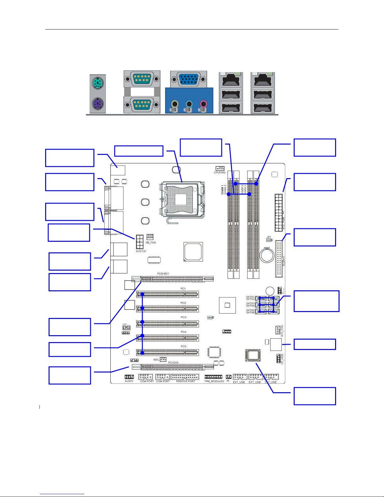
Connector Location
32-bit PCI
Slots
PCI Express
x16
Serial-
A
TA2
Connector
SATA1
,
2
,
3
,
4
,
5
,
6
ATX Power
Connector
Floppy
Connector
LAN#2
USB (J8)
LAN#1
USB (J7)
DDR2
Channel 1
PCI Express
x4 (x16)
PS/2 Keyboard
Mouse (J3)
COM1
COM2 (J5)
V
G
A
AUDIO (J7)
775 CPU Socket
ATX 12
V
Power (J9)
DDR2
Channel 2
BIOS
FWH
POST Dis
p
la
y
PS/2 Mouse
COM2
V
GA Gigabit LAN
Keyboard
COM1
A
UDIO USB4&5 USB6&7

ATXP-965Q Technical Reference Chapter 2 – Hardware Configuration
Chassis Plans 11
J10 Primary IDE Master SATA # 1
J9 Secondary IDE Master SATA # 1
J12 Primary IDE Slave SATA # 1
J11 Secondary IDE Slave SATA # 1
J14 Third IDE Master SATA # 2
J13 Fourth IDE Master SATA # 2
Header and Jumper Location
USB2&3
USB0&1
USB8&9
Front Panel
IR (J22)
TPM Module
(J21)
SYS_ FAN
(J17)
Printer Port
(J20)
COM4
COM3
HD-AUDIO
AUX IN (J18)
CD-IN (J15) SPI-CON (J16)
CMOS Reset
(JP1)
Power LED
NB_FAN (J6)
CPU_FAN (J1)
J4
Speaker
BIOS Select
(J26)

Chapter 2 – Hardware Configuration ATXP-965Q Technical Reference
12 Chassis Plans
Connectors, Headers and Slots Quick Reference Table
Connector Name Description
ATX_PWR ATX Power Connector 24-pin connector
AUX12V ATX 12V Power Connector 8-pin connector
J7 / J8 RJ45 LAN Port + USB Conn. RJ-45 Connector and USB
Conn.
PS/2 KB/MOUSE(J2) PS/2 Mouse & PS/2 Keyboard
Connector 6-pin mini-DIN Female
AUDIO/VGA(J5) Audio Line In/Out MIC Connector 3 phone jack connector
VGA Display Connector 15-pin Female connector
COM1/COM2(J4) Serial Port COM1 Connector 9-pin DB-9
Serial Port COM2 Connector 9-pin DB-9
FDD Floppy Driver Connector 34-pin shrouded header
SATA1~6(J9,J10,J11,J12,
J13,J14) Serial-ATA2 Port Connector 7-pin shrouded connector
Header Name Description
AUDIO Line-Out, MIC Headers 10-pin keyed header
EXT_USB(0&1)(J23)/
EXT_USB(2&3)(J24)/
EXT_USB(8&9)(J25)
USB Port Headers 10-pin shrouded header
SPK Legacy Speaker connector 4-pin header
FP_HDR Front Panel Header
(including Power LED/ IDE activity LED/
Reset switch / Power On Button lead)
10-pin keyed header
CPU_FAN (J1) CPU FAN Power Header 4-pin connector
SYSFAN(J17),
NB_FAN(J6) FAN Power Headers 4-pin connector
IR(J22) IR connector 6-Pin keyed header
PRINTER PORT(J20) Parallel Port header 26-Pin header
COM3/COM4 COM Port Header 10-Pin shrouded header
AUX-CD(J15) AUX CD Audio –In Headers 4-Pin header
CDIN(J18) CD Audio-In Headers 4-pin header
PWR_LED Legacy Power On LED 3-pin header
Table of contents
Other Chassis Plans Motherboard manuals

Chassis Plans
Chassis Plans JXT6966 Use and care manual

Chassis Plans
Chassis Plans ATXP-945G Use and care manual

Chassis Plans
Chassis Plans MTXP-945G Use and care manual

Chassis Plans
Chassis Plans MX8 Use and care manual

Chassis Plans
Chassis Plans ATXN-5520 Use and care manual

Chassis Plans
Chassis Plans ATXR-QZ45Q Use and care manual

Chassis Plans
Chassis Plans ATXP-875P Use and care manual


