Checkmate TR3 User manual
TR3 Tripod
User Manual
ANSI Z359.18-2017
TR3 Tripod
Issue 0
TR3 Tripod
User Manual
Page
INDEX
1.0 Introduction to TR3 &
Scope of Use
2.0 Assembly
3.0 Confined Space Recommendations
4.0 Storage, Issue & Inspection
5.0 Quality, legislation & Exclusions
6.0 Installation, Use, Opening/Clearance
Requirements & Fall Clearance
7.0 Warning! & Compatibility
8.0 Labeling
9.0 Record Card
3
4 - 6
7 - 8
9
10
11 - 12
13
14
15
WARNING!
Working at height is dangerous. This product is designed to reduce
the risk of working at height, by providing protection in the event of a
fall to reduce the risk of injury. The product must be used as intended,
and the user must be trained, competent, and aware of the correct
usage and limitations of the product. The user MUST be supplied
with the manufacturers user instructions and MUST read and fully
understand and follow the instructions within. The user must also
comply with OSHA and local safety regulations.
Failure to follow these guidelines could result in injury or death.
The Checkmate TR3 meets the requirement of ANSI Z359.18-2017, A10.32.12,
OSHA 1910 and OSHA 1926 Subpart M

Issue 0
TR3 Tripod
User Manual
Introduction to TR3 & Scope of Use
PAGE 3 Section 1.0
TR3 Tripod
The TR3 Tripod has been designed for your safety. The TR3 is supplied as a passive fall arrest device. The
device is designed to be used above structures and confined entry areas where other attachment is not
possible. The TR3 is totally portable and is therefore a temporary anchorage. In the event of a fall the
Tripod will provide a tested anchorage and a secondary anchorage for rescue if required. If in any doubt
please clarify application with Checkmate Technical Support.
Head Pulley x 2
Locking tabs x 3
WG-01
Mounting Bracket
Leg Pins x 3
FABX2R or
FABXLR
Swivel Feet x 3
Anti-splay
Webbing
Eyebolt Attachment x 2
Position A = Max extension with bracket fitted
Position B = Min extension with bracket fitted
Position C = Min extension - no bracket (connect to eyebolt only)
Position HTHED
A 94 87 56
B 71 63 39
C 71 63 39
All measurements in inches
HT = Height to top of TR3 crown
HE = Height to bearing point of eyebolt
D = Diameter to inside of feet
For opening and clearance requirements please
see p.g. 11
Principal Materials:
Aluminum, stainless steel, galvanized steel,
powder coated steel, polyester, nylon
PART NO. DESCRIPTION
32200 Height adjustable tripod (TR3) & carry bag
32208 Tripod carry bag only
32205 Tripod (TR3), tripod bag, 65ft work winch (WG-01), winch adaptor bracket (WG-02), 60ft galvanized SRLR (FABX2R) &
SRLR adaptor bracket (FABXR-DB)
32206 Tripod (TR3), bag, 65ft work winch (WG-01), winch adaptor bracket (WG-02), 100ft galvanized SRLR (FABXLR) & SRLR
adaptor bracket (FABXLR-DB)
32207 Tripod (TR3), bag, 65ft winch (WG-01) & winch adaptor bracket (WG-02)
Model Designation

Issue 0
TR3 Tripod
User Manual
Assembly
Page 4 Section 2.0
NOTE:
The Checkmate TR3 and FABX2R/FABXLR are designed for rescue use only. If the device is to be used as
a primary man riding winch Checkmate recommend the use of a secondary rescue device. The device is
designed to be used in free running mode and in the event of a fall the user can be rescued via the winching
facility. For advice or further information contact Checkmate.
Fig. 1
Unpack tripod and stand upright.
Fig. 2
Release leg pins and slip up to
desired height.
Fig. 3
Lock individual legs with pins.
Fig. 4
Open legs out and ensure sprung
loaded tabs lock out in position.
Fig. 5
Check anti splay webbing is
secure.
Fig. 6
Ensure feet are sitting flat on the
ground as shown when used on
hard ground, or fully folded back
for use on soft ground.
Spiked Feet
Flat Feet
Issue 0
TR3 Tripod
User Manual
Assembly
Page 5 Section 2.0
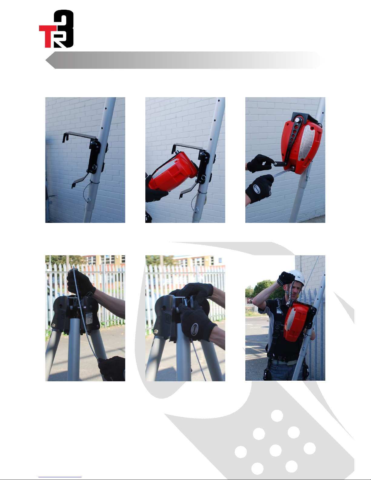
Fig. 7
Fix FABXR-DB or FABXLR-DB with
two supplied pins.
Fig. 8
Insert FABX2R or FABXLR into
the bracket as shown seating the
cable end in the bracket
Fig. 9
Secure with M12 bolt.
Fig. 10
Pull cable up to tripod head and
insert hook through central hole.
Fig. 11
Slide sprung loaded pulley to right,
insert cable in pulley groove, and
release pulley.
Fig. 12
The device is now ready for use.
Follow the instructions for safe
use of other equipment.
Folding:
Reverse the above procedure, ensuring that the sprung loaded leg locking pins are released by hand before
folding each leg. It is acceptable to leave the FABX2R fitting in the FABXR-DB Bracket when removing from
the TR3.

Issue 0
TR3 Tripod
User Manual
Assembly
Page 6 Section 2.0
Fig. 1
Slide the bracket (WG-02)
which is fixed to the winch
onto the tripod leg.
Fig. 2
Align the holes in the bracket
with the holes in the tripod leg
and insert a detent pin.
Fig. 3
Insert the second detent pin.
Fig. 4
Pull cable up to tripod head
and insert hook through
central hole.
Fig. 5
Slide sprung loaded pulley to
right, insert cable in pulley
groove, and release pulley.

Issue 0
TR3 Tripod
User Manual
Page 7 Section 3.0
Confined Space
Recommendation Option 1
Primary Fall Arrest Device with Secondary Backup
When entering a confined space when a fixed access system is installed the user should use:
1 x Tripod (TR3)
1 x SRLR (FABX2R or FABXLR)
1 x SRLR adaptor bracket (FABXR-DB or FABXLR-DB)
The FABX2R/FABXLR should be in free run mode and in the event of a fall the device will automatically lock
on and then the winch can be engaged.
PLEASE NOTE THAT THE FABX2R/FABXLR IS NOT INTENDED TO BE USED AS A CONTINUOUS
WINCH, ONLY AS A RETRIEVAL DEVICE IN EMERGENCY SITUATIONS.
FABX2R or
FABXLR
Issue 0
TR3 Tripod
User Manual
Page 8 Section 3.0
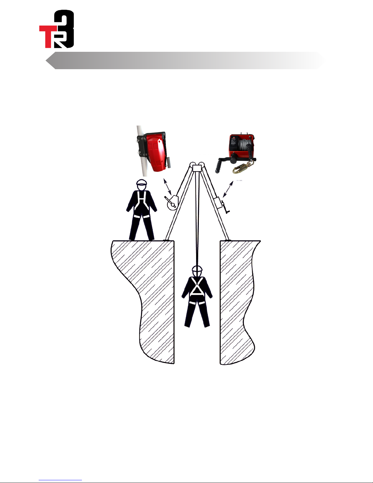
Primary Raise and Lower Device with Secondary Backup
Confined Space
Recommendation Option 2
FABX2R or
FABXLR
WG-01
When entering a confined space when there is no fixed access system and there is a need to lower the
user down under control, you should use:
1 x Tripod (TR3)
1 x SRLR (FABX2R or FABXLR)
1 x SRLR adaptor bracket (FABXR-DB or FABXLR-DB)
1 x Work winch (WG-01)
1 x winch adaptor bracket (WG-02)
The WG-01 is your primary lowering device and in the event of a fall the FABX2R/FABXLR will
automatically lock on and the winch can be engaged.

Issue 0
TR3 Tripod
User Manual
Storage, Issue & Inspection
Page 9 Section 4.0
Storage
Storage in a central protected location allows assurance of inspection on issue and return
This tripod should be stored in a clean dry place where it can be protected from damage by chemical attack and sharp
objects . It should be stored with its instructions and record card at all times.
After use return to the store, Never leave the device lying around site.
Cleaning
To clean the tripod a mild detergent can be used with warm or cold water and then dry with a clean soft cloth.
Issue
This and associated equipment must be visually inspected by a competent person when initially delivered to site, there
after the product must be inspected before and after use. A record card is printed on the reverse of this manual and
should be updated after each routine inspection. Follow the points laid down in the section headed “Inspection” without
deviation.
The supervisor must ensure that the equipment is being used correctly and that the user is aware of its safe use and
inspection. Additionally the supervisor must ensure that the site to which the device is to be used has been approved fit
for use and is in a good condition.
Inspection & Maintenace
Inspect the device for corrosion or damage.
Check the head and leg pins for signs of wear or damage and replace wear necessary.
Pay attention to condition of leg tubes for damage, bends and hole wear.
Check the sprung loaded locking tabs self-engage when the legs are opened.
Check the sprung loaded pulleys return to central position when slid to the side and released.
Check the condition of the pulley and eyebolt attachment. Pulleys should run free, but the eyebolt must be fixed.
Check rubber pads are fitted and not missing on feet.
Check the condition of the entire length and buckle of the anti-splay tape for damage.
Check the device opens and closes fully.
Tripods which fail inspection must be removed from the field of service immediately and marked out of service. If
irreparable the Tripod must be destroyed and discarded to prevent further use.
Ensure that device certification is current before use, the device must have been serviced within the last 12 months and
3 months if used in corrosive or off-shore environments.
If for any reason the inspection of this device shows signs for concern or doubt then the device must be
quarantined and removed from service immediately. Qualification should be sought from the supervisor and if
still concerned the device must be sent to the supplier, an approved service agent or the manufacturer for
service and re-calibration.
This device must only be serviced by the manufacturer or a trained and competent individuals
approved by the manufacturer.
Never attempt to service this device or tamper with its function in any way.

Issue 0
TR3 Tripod
User Manual
Quality, Legislation & Exclusions
Page 10 Section 5.0
5.1 Quality
All Checkmate products are
manufactured under ISO 9001 and
to the highest standards. The scope of
use within the certification held allows
Checkmate to design, manufacture and
test Personal Protection Equipment.
Horizontal tensile test machine,
abrasion testers and dynamic drop test
rig are just part of the full range of test
facilities used to ensure ultimate safety
of our product range.
All Checkmate systems must only be
installed by Checkmate personnel or an
approved installer. Strict training is given
and written exam are completed before
full certification can be given to installers.
5.2 Legislation and Standards
The TR3 Tripod has been designed
to meet the requirements of ANSI
Z359.18:2017, A10.32.12,
OSHA 1910 and OSHA 1926 Subpart M
For clarification on any certification
issues contact Checkmate.
5.3 Exclusions
Checkmate holds global product
liability cover for your safety.
Checkmate will NOT however be
responsible for:
Users who are out of the scope of any
written manuals of training given.
Any systems that have NOT been
inspected under the current legislation.
Operators who do not use load limiting
PPE.
Devices that have been damaged.
The Max weight has been exceeded.
Devices that have NO serial number
markings, and the manufacturers name.
Checkmate Lifting & Safety Ltd present.
Rescue and Risk Assessment
Suitable planning and risk assessment
should be carried out by the user and or
supervisor. A suitable rescue plan and
equipment shall be in place to minimise
post fall suspension time. Checkmate
can offer a complete range of rescue
equipment to suit your requirements.

Issue 0
TR3 Tripod
User Manual
Installation & Use
Page 11 Section 6.0
Installation
As a minimum, when in use the tripod must always be
installed with either load lifting equipment i.e hand winch
and/or load limiting device i.e. SRLR.
The device must not be used where the following
hazards may endanger the user or prevent the efficient
operation of the system.
The area below the device must be free of obstruction
which may obstruct the movement of the user.
The environment must be free of heavy solvents or acids
that will degrade the device, lanyard or the hook.
The structure to which the device stands must be in good
condition and suitable for use
The webbing anti splay strap must be fitted and tensioned
prior to use, check all pins are inserted and secured.
Only install on flat level ground on a stable surface. Ensure
footing is stable and can support the intended load. (see
below)
The mounting surface onto which the tripod will be installed
must meet the requirements of ANSI Z359.18:2017 and
the criteria stated below:
Fall arrest:
The mounting surface on which the tripod will stand,
selected for personal fall arrest systems (PFAS) must be
capable of withstanding a static load of at least 3,600lbs
(16kN) (1) in all directions permissable by the PFAS
when certification exists ( see ANSI Z359.18-2017 for
more certification details). In the absence of certification
the mounting surface must be capable of withstanding
5,000lbs (22.2kN) (2) of static force. If more than one
tripod is to be installed on the mounting surface for
simultaneous fall arrest use, the static strengths (1) & (2)
must be multiplied by the number of systems attached to
the mounting structure.
Work Positioning:
The mounting surface must be capable of withstanding
a static force of 5,000lbs (22.2kN) in all directions
permitted by the work positioning surfaces.
Material Handling:
The mounting surface must be capable of withstanding a
static load of 2,500lbs (11.1kN) in all directions permitted
by the handling equipment.
Rescue:
The mounting surface must be capable of withstanding a
static load of 2,500lbs (11.1kN) in all directions permitted
by the rescue equipment.
The minimum strength of the TR3 is 5,000lbs (22.2kN)
Use
Fall Protection
Check the anchorage to ensure it has not been damaged,
follow the inspection routine laid down in this manual.
The device will arrest a fall normally within the specification
of the device attached in normal use the anchorage can
only be used with devices or systems where a shock
absorber or device with shock absorption is used limiting
arrest forces to below 1,800lbs (8 kN).
Connection is either in the leg plane from the mounting
bracket or vertically downward from the anchorage
points. For details please ask your local Checkmate
representative.
The unit is designed to used within systems that limit the
force in a fall to less than 1,800lbs (8kN) on the user.
Rated for one worker, or two workers during assisted
rescue. Each worker must attach to a separate connection
point.
Worker capacity range (including all equipment): 130-
310 lbs. If used in assisted rescue, maximum combined
worker capacity is 620 lbs. If used for equipment hoisting,
maximum
equipment weight is 551 lbs./250 kg.
Materials Handling
The TR3 may be used for materials handling with a
maximum load of 550lbs (250kg) and a suitable winch.
Ensure that the TR3 is not subjected to any shock loads,
and that the stability of the TR3 is not compromised. Do
not use the TR3 for materials handling and PPE at the
same time.
Do not attach more than one personal fall arrest system
to the tripod unless certified for such purpose.
Opening & clearance requirements
Maximum hole diameter (tripod max extension): 36”
(3.75ft)
Maximum hole diameter (tripod min extension): 21”
(1.75ft)
Minimum foot to opening distance: 9”
Minimum head clearance: 48”/4ft (ground to obstruction
distance)
Maximum tripod footprint diameter: 56” (4.7ft)
It is imperative that proper maintenance of adequate
clearance around and within the tripod is upheld to
provide unrestricted movements in, through, and
around the tripod and minimizing tripping or other
events which may result in dislodging the tripod.
For fall clearance requirements see page 12.

Issue 0
TR3 Tripod
User Manual
Fall Clearance
Page 12 Section 6.0
Issue 0
TR3 Tripod
User Manual
Warnings! & Compatability
Page 13 Section 7.0
Warnings!
Read and understand manufacturers instructions before
inspection, installation or use of this product. Do Not use if
you weigh more than 310lbs (141kg). Only use approved
equipment with Tripod. If there are any points in this manual
that you are unsure of seek a competent, trained person to
advise you before using.Seek medical advice from a doctor
before using this product if, you have sustained a spinal
injury, suffer from a neck or back complaint, or you are taking
prescription medication. Never use if you are under the
influence of alcohol or recreational drugs. Extra care should
be taken if welding whilst using this product, protect the device
from splatter and heat at all times. The TR3 tripod must only
be installed on flat level ground with a stable surface using
the installation procedure provided within this document. If
subjected to the forces of arresting a fall, the tripod must
be removed from service immediately and inspected by an
authorised person.
Never attempt to:
• Alter the device;
• Misuse the equipment;
• Combine components or subsystems, or both, which
may interfere with the safe function of each other;
• Expose the equipment to chemicals which may
produce a harmful effect, consult the manufacturer if
in doubt;
• Use the equipment around moving machinery and
electrical hazards;
• Use the equipment around sharp or abrasive surfaces
• Use the equipment without the minimum protection
equipment installed to the tripod i.e hand winch and/
or SRLR.
Service temperature Range: (-30°F / -34.4°C) - (130°F /
54°C)
NOTE: The Checkmate TR3 and FABX2R/FABXLR are
designed for rescue use only. If the device is to be used as
a primary man riding winch Checkmate recommend the use
of a secondary rescue device. The device is designed to be
used in free running mode and in the event of a fall the user
can be rescued via the winching facility. For advice or further
information contact Checkmate.
Compatibility
The tripod is suitable for fall arrest when used with a Full
Body Harness (approved to ANSI Z359.11-2014), suitable
shock absorbing lanyards (approved to ANSI Z359.3-2013),
suitable non-shock absorbing lanyards (approved to ANSI
Z359.3-2017)
Compatible SRLs and SRLRs for recovery (approved to ANSI
Z359.14-2014). Hand winch (approved to ANSI Z359.4)
hand winch must be used with secondary back up. This unit is
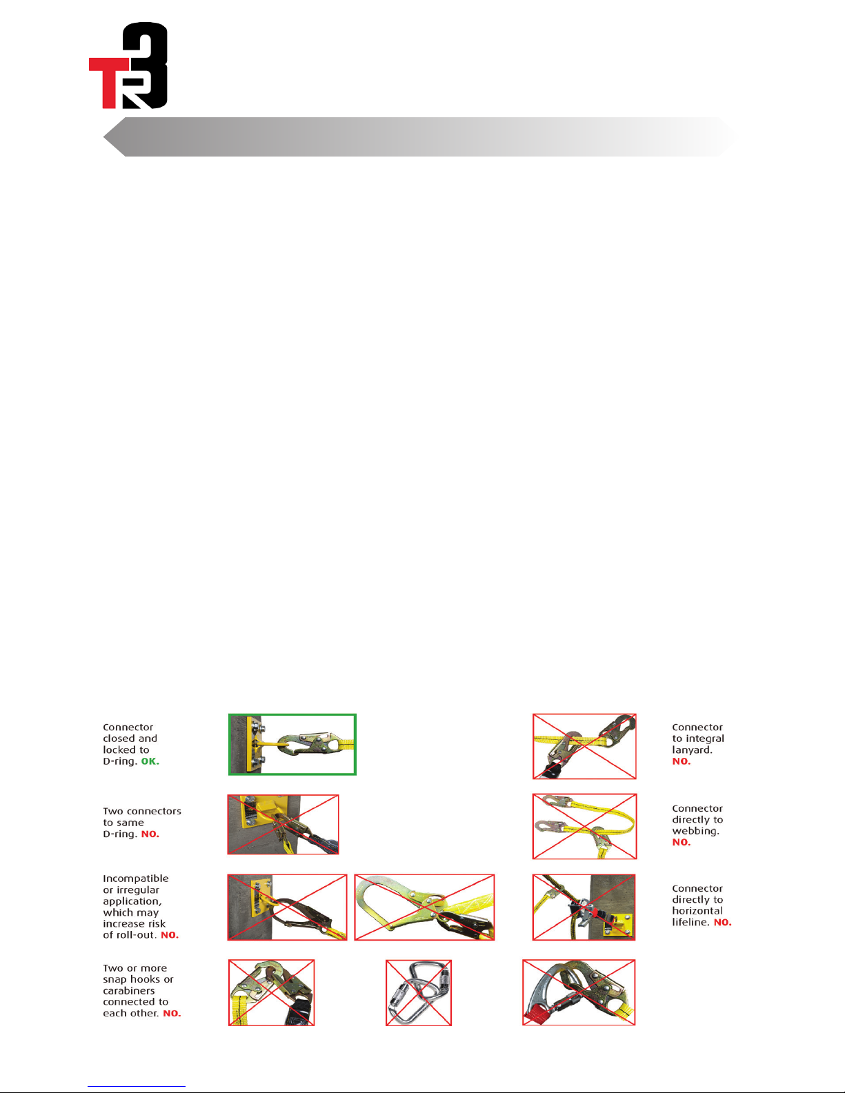
not suitable for use in explosive atmospheres. When making
connections with TR3, eliminate all possibility of roll-out. Roll-
out occurs
when interference between a hook and the attachment point
causes the hook gate to unintentionally open
and release. All connections must be selected and deemed
compatible with TR3 by a Competent
Person. All connector gates must be self-closing and self-
locking, and withstand minimum loads of 3,600 lbs.
See the diagram below for examples of compatible/
incompatible connections.
Issue 0
TR3 Tripod
User Manual
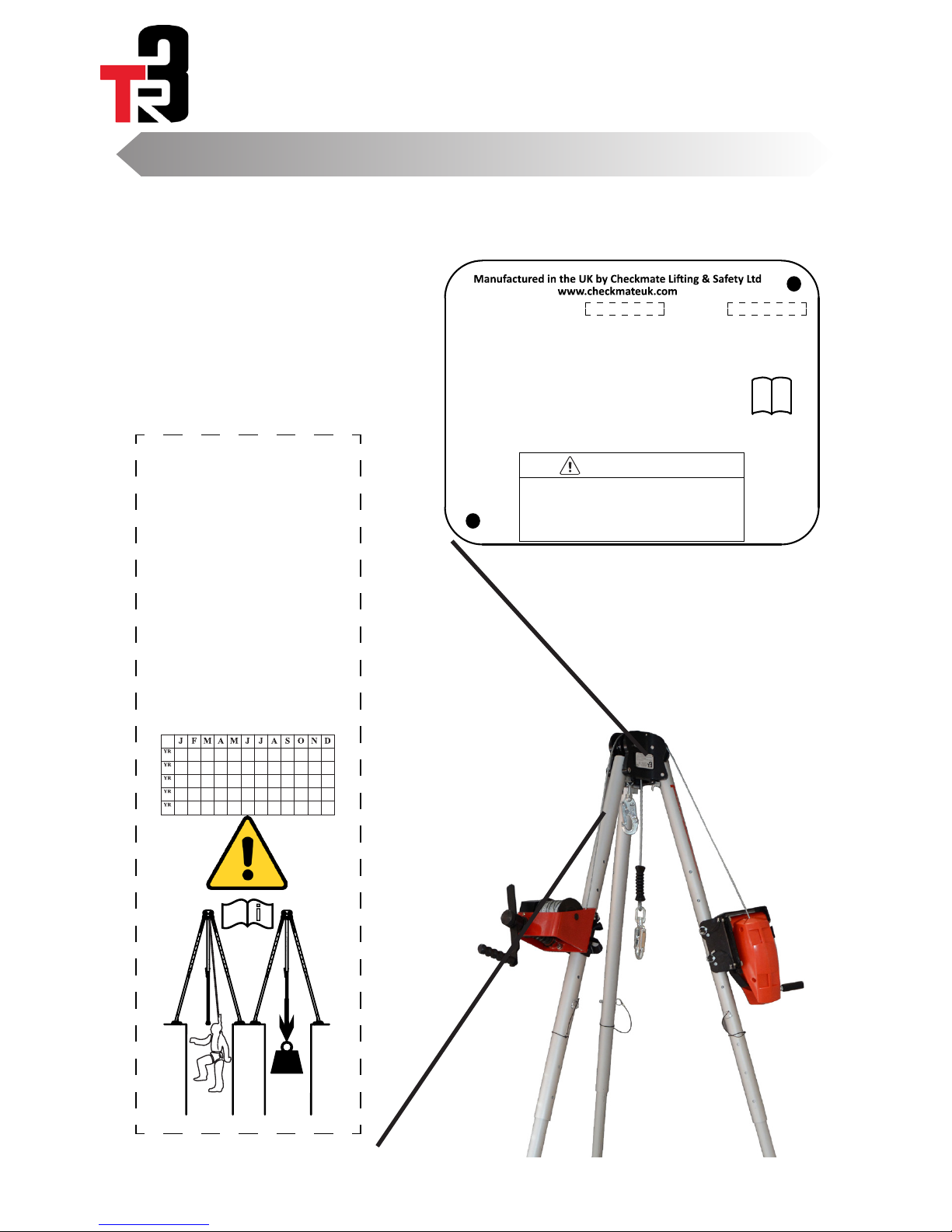
Labeling
Page 14 Section 8.0
i
Manufacturer’s instructions supplied with product must
be followed at all times. Alteration or misuse of this
product, or failure to follow instructions, may result in
serious injury or death. Avoid contact with hazards,
including, but not limited to, heat, chemicals, electricity,
and sharp or abrasive edges and surfaces.
WARNING
46MM
60MM
DOM: Serial #:Model #: 32200
= cut-out for screw
= cut line for laser engraving
Notes:
ANSI Z359.18-2017 & A10.32-12 / OSHA 1926 Sub M & 1910
Type A Anchorage connector
Only make compa�ble connec�ons
5,000 lb. MBS (min. breaking strength).
Min. service temperature: -30�F
Inspect prior to each use. Competent person must
inspect and record at least every 12 months
PPELAB-333 IS4
CHECKMATE
All Intellectual Property, including drawings, branding, logo's and patents are owned by Checkmate Limited.
1:1
+44(0) 1795 668 280
+44(0) 1795 580 333
New Road, Sheerness, Kent, England ME12 1PZ, UK
www.checkmateuk.com
LET'S INNOVATE
CHECKMATE LIFTING & SAFETY
LTD
LIFTING & SAFETY
1
MAX
551lbs/
250kg
MAX
310lbs/
141kg
MAX USER WEIGHT - 310lbs/141kg
WLL - GOODS - 551lbs/250kg
PPELAB-405 ISS 4
INSPECTION GRID
Prior to use, read and understand all manufacturer's
instruc�ons provided with equipment at �me of
shipment from manufacturer.
Compliant with OSHA 1910, OSHA 1926 Subpart M, ANSI
Z359.18-2017 and ANSI A10.32-12.
Worker capacity range (including
all equipment): 130-310 lbs.
If used in assisted rescue, maximum
combined worker capacity is 620 lbs.
equipment weight is 551 lbs./250 kg.
limited to, heat, electricity, chemicals, and sharp or
abrasive edges and surfaces.
inspect at least every 12 months.
point.
White Background
55mm(W) x 171mm(L)
PPELAB-405
ANSI TR3 Leg label 4
PPELAB-405
Cut Line

Issue 0
TR3 Tripod
User Manual
Record Card
Page 15 Section 9.0
SERIAL NO:
PRODUCT CODE:
DATE OF FIRST USE:
USER:
DATE CONDITION OF SYSTEM INSPECTED BY

UM-131_PSGTR3_IS0
Checkmate Lifting & Safety Ltd, Sheerness, Kent. England. ME12 1PZ, UK
Approved service company:
Table of contents


