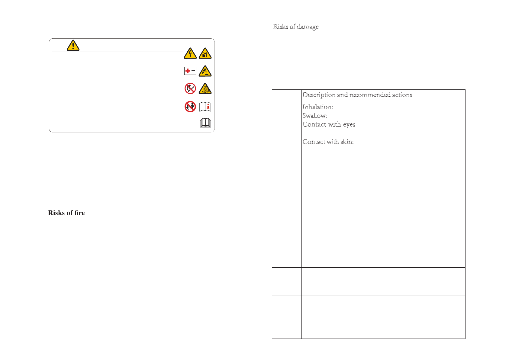
Growatt GBLI 6532 User manual

Date: 2020/ /
Version: V .0

No. Revision Contents Drafter Reviewer Version Date
1 N/A Chen Le Shen Zhengbin
Li Bing
Guo Yihao
V1.0 2020-07-24
2Added the icon “read the manual
before operating”
Updated the caution about the
two-pole breaker
Wang Qian Shen Zhengbin
Guo Yihao
Ni Yunlong
V2.0 2020-08-30

This document describes the application scenarios, installation,
electrical connection, commission and troubleshooting of 6.5kWh
Residential Energy Storage Battery (hereinafter simply put as battery).
Before installing and operating battery, please ensure that you are
familiar with product features, functions, and safety precautions as
provided in this document.
Warning and caution messages are listed in the document to remind
users, installers and maintainer of safe operation.
Indicates a potentially hazardous situation, if not
avoided, could result in serious injury or death.
Indicates a potentially hazardous situation, if not
avoided, may result in minor or moderate injury.
Symbol Description
!
WARNING
!
CAUTION
Table of Contents
1 Safety...............................................................................................1
1.1 Warning Label..........................................................................1
1.2 Precautions ...............................................................................2
1.3 Responses to Emergencies.......................................................2
1.4 Storage safety ...........................................................................3
1.5 Transportation Safety .............................................................. 3
2. Introduction to Product................................................................4
2.1 Intended Purpose .....................................................................4
2.2 Function ....................................................................................4
2.3 Appearance ...............................................................................4
2.4 Technical Parameters...............................................................5
3 Installation......................................................................................6
3.1 Basic Installation Requirements.............................................6
3.2 Installation Required Tools .....................................................7
3.3 installation Procedures ............................................................7
3.3.1 Wall Mounted Installation ................................................8
3.3.2 Floor Standing Installation ...............................................9
4 Electrical Connection.....................................................................10
4.1 Preparation...............................................................................10
4.2 Electrical Connection Procedures ..........................................10
5 Installation Steps under Parallel Connection..............................13
6 Power on/off Battery......................................................................15
6.1 LED Indication.........................................................................15
6.2 Troubleshooting........................................................................16
6.3 Power on Battery......................................................................17
6.4 Power off Battery .....................................................................17
7 Maintenance ..................................................................................18
7.1 Preparation...............................................................................18
7.2 Battery Replacement ...............................................................18
7.3 Firmware Upgrade...................................................................18

1
Do not dispose battery in household trash.
Recyclable.
Certification in European Union area.
Risk of electric shock.
Explosive gas.
Battery may leak corrosive electrolyte.
Battery is heavy enough to cause severe injury.
1 Safety
1.1 Warning Label Do not reverse polarities.
Do not expose battery to flame.
Operate as specified by the manual.
Read this manual before operating.

2
Label
1.2 Precautions
Risks of electrolyte leakage
* Do not subject battery to strong impact.
* Do not crush or puncture battery.
* Prevent battery from falling. In case of fall, turn off the battery
immediately and stop using it.
* Do not open or mutilate batteries. Released electrolyte is
harmful to the skin and eyes.
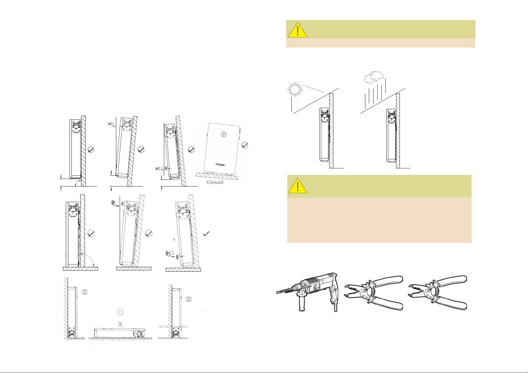
* Do not expose battery to direct sunlight.
* Avoid contact with conductive objects such as wires.
* Keep battery away from fire source, inflammable, explosive
and chemical materials.
* Do not dispose of batteries in a fire. The batteries may
explode.
Risks of electric shock
* Do not touch battery with wet hands.
* A battery can present a risk of electric shock and burns by
high short-circuited current.
* Battery installation and wire connection must be operated by
professionals.
1.3 Responses to Emergencies
Event Description and recommended actions
Leakage Inhalation: leave the contaminated area right now.
Swallow: induce vomiting.
Contact with eyes: flush eyes with flowing water for 15
minutes.
Contact with skin: wash thoroughly with soap and water.
Immediately seek for medical intervention after taking
emergency measures.
Fire Battery may catch fire when heated above 150℃ . Please
implement the following actions:
1. Extinguish fire before the battery catches fire. ABC
or carbon dioxide extinguisher is recommended.
2. If the fire is too strong to put out, move battery to
a safe place before it catches fire.
3. If battery is on fire, evacuate people first before
seeking help from professional fire protection
personnel.
4. If battery catches fire during charging, turn off
the breaker between battery and PCS when safety
can be guaranteed.
Wet
battery
If battery became wet or has been submerged in water,
do not access it. Immediately contact your distributor for
technical assistance.
Damage Damaged battery is dangerous and must be handled with
utmost care. They are not usable for use and could pose a
safety threat to people or property. If battery is suspected
to be damaged, stop any operation and return it to
distributor.
Risks of damage
* Keep a distance to water source.
* Do not subject battery to high voltage.
* Place battery on a flat surface. Do not place any foreign objec t
on top of battery nor step on battery.
* Battery-connected PCS should have reinforced insulation.
WARNING AVERTISSEMENT
1. Do not disassemble or alter the battery in any way.
Ne démontez ni modifiez la batterie en aucune façon.
2. Do not use the battery for purposes not described in its documentation.
N'utilisez pas la batterie à des fins non décrites dans sa documentation.
3. Do not drop, strike, puncture, or step on the battery.
Ne laissez pas tomber, ne heurtez pas, ne percez pas et ne marchez pas sur la batterie.
4. In case of electrolyte leakage, keep leaked electrolyte away from contact
with eyes or skin, immediately clean with water and seek help from a doctor.
En cas de fuite d'électrolyte, gardez l'électrolyte qui fuit loin du contact avec les yeux
ou la peau, nettoyez immédiatement avec de l'eau et demander de l'aide à un médecin.
5. Do not put the battery into a fire. Do not use it or leave it in a place near fire, heaters,
or high temperature sources.
Ne mettez pas la batterie au feu. Ne l'utilisez pas et ne le laissez pas dans un
endroit près de feu, de radiateurs ou de sources de températures élevées.
6. Do not submerge the battery in water, or expose it to moisture.
Ne plongez pas la batterie dans l'eau et ne l'exposez pas à l'humidité.
7. Do not allow the terminals to contact exposed wire or metal.
Ne laissez pas les bornes entrer en contact avec du fil ou du métal exposé.
8. The battery is heavy and can cause injury if not handled safely.
La batterie est lourde et peut provoquer des blessures si elle n'est pas manipulée en toute sécurité.
9. Keep out of reach of children or animals. Tenir hors de portée des enfants ou des animaux.

3
1.4 Storage safety
* Place battery according to signs on packing case.
* Do not put battery upside down or sidelong.
* Store batteries in a place free from direct sunlight and rain.
* Keep batteries at least two meters away from a heat source (such
as a radiator).
* Avoid contacting with corrosive and organic substances
(including gas exposure).
* Batteries with deficiencies should be separated from normal
batteries by setting wall between or placing in difference fire
protection zones.
* Ambient temperature ranges between -30℃ to 60℃ during the
first seven days, and ranges between-20℃ to 45℃ within six
months. Relative humidity ranges between 0%RH-95%RH.
* Keep the storage area dry, clean and well ventilated.
* Do not dispose of battery into environment or sewerage.
It should be recycled and disposed based on the local legislation
and regulations.
1.5 Transportation Safety
Battery has cleared UN38.3 (Section 38.3 of the sixth Revised Edition of
the Recommendations on the Transport of Dangerous Goods: Manual
of Tests and Criteria) and SN/T 0370.2-2009 (Part 2: Performance Test
of the Rules for the Inspection of packaging for Exporting Dangerous
Goods). The battery is classified as class 9 dangerous goods, and is
subject to land and water transportation. It is mandatory to report to the
airline company and obtain approval before air transport.
* Before transportation, press POWER button for two seconds and
five LED lights flicker for three times to power off battery.
* Do not pile up foreign objects on the top of battery. Four batteries
at most can be piled up.
* Maintain original packaging and keep labels complete and
recognizable.
* Prevent from direct sun exposure, rain, condensation and
mechanical damages.
* The battery is current qualified for land and sea transport. As respect
to air transport, the battery is subject to mandatory certificates.
* During transportation, put battery flat, do not have battery stand
on or lean against the floor to avoid possible crash.
* Maintain temperature between -20℃ to 45℃ during the
transportation.
* Prohibit mixing up with explosive, inflammable or toxic objects.
* Use van-type vehicle including container and metallic van-type
vehicle. Platform vehicle and convertible are prohibited.

4
2. Introduction to Product
2.1 Intended Purpose
The battery is a 6.5kWh LiFePO4 pack. It has a 48V battery module as
the main power supply unit which composed of 32 pieces of 64Ah cells
in two parallel and sixteen serial connect (2P16S). Battery coordinates
with PV, PCS, Grid, DC Breaker and loads in the residential energy
storage system. The four typical application scenarios are as shown
Battery powers loads at nighttime
when there is no PV. If battery
energy is insufficient, it can
supply loads together with grid.
Battery can be charged by grid.
Users are suggested to store
energy from grid to battery when
electricity price is relatively lower.
*
Power-off triggered by fault: battery powers off if level three
under voltage, 0V cell or parallel connection failure happens.
*
Forced power-off: when battery does not connect to mains
supply, press POWER button for two seconds and battery
powers off.
*
Activation: input 48V-57.6V/2S-5S via P+/P- terminals, battery will
be activated from off mode to standby status.
2.3 Appearance
The battery is an energy storage unit composed of cells, mechanical
parts, battery management system (BMS) as well as power and signal
terminals. Product dimension (unit: mm) and appearance are as
shown below:
2.2 Function
Compared with normal batteries, the battery is characterized with
better charging and discharging performance, longer cycle life and
less self-discharging loss. The build-in BMS can monitor battery
operation status and alarm timely to avoid operation out of limit. A
maximum of 8 batteries can be parallel-connected to expand energy
and power of energy storage system. Battery realizes communication
with PCS via CAN or RS485 network port.
*
Monitoring: detect the voltage and temperature of cell, the
voltage and current of battery.
*
SOC estimate: indicate the precise volume of remaining
electricity.
*
Alarm: alarm when overvoltage, under voltage, overcurrent,
over temperature or under temperature occurs.
*
Protection: protect against over voltage, under voltage, over
current, over temperature, under temperature, cell fault and
hardware failure.
*
Report: report alarm messages and operation data to PCS via
CAN or RS485 network ports.
*
Parallel connection: support a maximum of 8 batteries in
parallel connection.
The energy produced by PV is
optimized to supply loads. The
excess energy is used to charge
battery, then export to grid.
When grid falls, battery and PV
can power loads.
Each battery shall be equipped with an two-pole DC breaker as:
Rated Voltage≥120Vdc Rated Current≥150A
Cut-off current: 2200A
!
CAUTION
Breakers are provided by your system supplier.
The quantity of breakers must be consistent with that of the battries.

5
2.4 Technical Parameters
475
765
150
148
745
No. label Name No. label Name
1 POWER Power button 5 Link-out Parallel Network Output
2 + Positive terminal 6 Grounding terminal
3 _ Nagative terminal 7 PCS Network port to PCS
4 Link-In Parallel Network
Input
8 Safety vent A vent to release pressure
inside.
1 Usable Capacity 118Ah
Step 1: rest the battery for 5 minutes;
Step 2: charge (CC=23.6A) until Vcell-max=3.48V;
Step 3: charge (CC=11.8A) until Vcell-max=3.5V;
Step 4: charge (CC=2A) until Vcell-max=3.5V;
Step 5: stop charging and rest the battery for 60 minutes;
Step 6: discharge (CC=0.2C) until Vcell-min=3.0V;
Step 7: stop discharging and rest the battery for 5 minutes;
repeat step 2-step 7 for 3 cycles.
2 128Ah/
3
6.5kWh
4 Usable Energy 6.0kWh
5 Nominal Voltage 51.2Vdc
6 Operating Voltage 48Vdc~57.6Vdc
7Max. Charging Current
(temperature refere to the cell surface
temperature)
-10℃ -0℃ : 21.3A 0℃ -5℃ :32A
5℃ -15℃ :64A 15℃ -45℃ :104.2A
45℃ -50℃ :64A 50℃ -55℃ :32A
8Max. Discharging Current
(temperature refere to the cell surface
temperature)
-10℃-0℃ : 21.3A 0℃-45℃:104.2A
45℃ -50℃ :85.3A 50℃ -55℃ :32A
9 Norminal Charging and Discharging
powern
3.3KW
10 Short Circuit Current 2200A/4ms
11 Max. Charging and Discharging power 5kW
12 Peak Charging and Discharging power 6.9kW/3s
13 Operating Temperature -10℃ ~50℃
14 Cycle Life(25℃) 6000 cycles
15 RTE >95%, 0.2C charge/discharge 25℃
16 DOD/EOL 94.5% ≥ 6000cycle/60%EOL
17 Cooling Natural cooling
18 Dimension/Weight W475*D148*H745 mm/58kg
21 Installation Wall mounting installation or
floor standing installation
20 Protection class / Ingress protection Class I / IP55
21 Cell safety certification IEC62619/UL1973
22 PACK safety certification IEC62619/CE/RCM/CEC
23 UN transportation test standard UN38.3
24 Communication CAN; RS485
25 Parallel Connection Eight batteries
26 Storage conditions Store for seven days during -30℃ ~
+60℃;store for six month under
-20℃ ~ +45℃ , 0%-95%RH.
Unless otherwise specified, all tests stated above are conducted as:
Temperature:25±2℃ Humidity: 5%RH-95%RH
Norminal Battery Capacity / EnergyNorminal Battery Capacity / Energy
Rated Battery Capacity / Energy
128Ah/ 6.5kWh
118Ah/ 6.0kWh

6
3 Installation
3.1 Basic Installation Requirements
Battery can be installed indoors or outdoors. Ensure the following
conditions are satisfied:
*
A deviation of -5°≤θ≤5° is allowed for both installation
against wall and floor. Additionally, the distance between the
bottom part of battery and floor should range between 500mm to
1200mm. Please refer to figures below ( √ means acceptable
installation and X unacceptable).
5°
Ground Ground
Ground
Wall Wall Wall
90°
5°
Ground Ground
Wall Wall
Ground
5°
5°
500 ≤d≤1200
90°
500 ≤d≤1200 500 ≤d≤1200
* It is recommended to build sunshade & rain shelter to avoid direct
exposure to sunlight and rain.
3.2 Installation Required Tools
Drill Crimper Wire stripper
Keep the dirt or dust at a minimal level;
Do not install battery in a place where flood frequently occurs;
Do not install battery in highly humid area such as bathroom;
Ensure direct contact between battery shell and ambient air.
Do not cover or shield battery to avoid poor cooling.
Do not place the battery upside down nor keep it flat as above.
!
CAUTION
Wall Wall
!
CAUTION
Please follow the AS/NZS 5139 standard during the battery installation.

7
Screw driver Cable wrench Pencil
Tape measure Multi-meter Hydraulic plier
Insulated gloves Safety goggle Safety shoes
3.3 installation Procedures
before opening package, check for damages like
holes, cracks or other traces on exterior packing case. If any abnormity is
detected, do not open the package and contact your distributor.
after opening package, check if deliverables are
complete. If there is any part missing or damaged, please contact your
distributor.
Check and confirm the battery is powered off and breaker is open before
any further step.
RJ45 connector 2 PCS
Grounding Cable
M6 Nut
1 PCS
Warranty Card 1 PCS
Gradienter 1 PCS
Fastenings
M8 expansion screw 2 PCS
M8*H60 anchor 2 PCS
3.3.1 Wall Mounted Installation
Step 2 Fix bracket to wall.
Choose alloy drill bit with a diameter of 12mm and install it to a drill.
Drill in the spots that have been located in step 1 and have at
least 60mm drilling depth. Clean the soil and drive expansion tube
into the hole. One person puts the bracket on wall and minds to keep
gradienter horizontal. The other person drives M8 screw through the
bracket into hole.
Step 1 Confirm installation spot.
.noitallatsni eht etapicitrap snosrep owt tsael tA
One person places the bracket on wall and
ensures the gradienter horizontal; the other
person marks spots of screw driving.
After confirming the spots to drive screws,
put down the bracket.
The weight capacity of wall should exceed 4 times weight of battery.
Keep the distance between bracket, wall and floor as is shown
(320mm, 320mm, 765mm).
Installer should consider the specific wall shape before choosing four
drilling spots.
320mm 320mm
765mm
!
CAUTION

8
There are two spot drilling proposals available.
For installation on a wall with its main supporting beams at a distance
of 16 inches, it is recommended to adopt the first drilling spots.
For wall with its main supporting beam at a distance of 24 inches, it is
recommended to adopt the second drilling spots.
Proposal 1
Proposal 2
!WARNING
Step 3 Fix battery on bracket.
Rotate the left latch leftward and the right latch rightward until they
keep perpendicular to the battery. Install battery from the top down
and lock the connection part of battery with the support plate of
bracket.
Rotate the left latch
rightward until the notch
locks limiting pin, rotate
the right latch leftward until
the notch locks limiting pin
too.
Leave a minimum clearance of 133mm before the front surface of battery.
In order to guarantee a stable connection between battery and bracket,
please visually check if the two upper joints are fixed. Try to move the
lower part of battery away from wall. The connection is proved qualified if
the battery cannot be moved at all. Otherwise, please connect the battery
and bracket again until confirming a fixed connection.
Step 4 Insert power cable and network cable into battery terminals.
Check and confirm battery is well fixed to wall. Plug the power
cables into battery terminals and DC Breaker. Plug network cable A
into network ports of battery and PCS. Please refer to Section 4.2 for
cable making details.
!
CAUTION

9
3.3.2 Floor Standing Installation
Step 1 Confirm installation spot.
Place battery in the to-be installed area. Rotate the left latch leftward
and the right latc rightward until they are perpendicular to the
battery. Keep the distance between wall and battery as shown
(320mm, 320mm). Leave a minimum clearance of 133mm before
the front surface of battery. Use pencil to mark where the notches of
two latches are and confirm the two drilling spots. Move battery away.
Step 2 Install battery.
Choose an alloy drill bit with a diameter of 12mm and install it in the
drill. Drill two holes in the spots that have been confirmed in step
1. Keep the drilling depth as least 60mm. Clean the soil and drive
expansion tube into hole.
Move battery back to the place confirmed in step 1. Drive M8 screw
through notch of latch into wall.
to PCS Network Plug
Plug 1
to DC Breaker
Positive Terminal to DC Breaker
Positive Terminal
Plug 2
.
.
Step 3 Insert power cables and network cable into battery terminals.
Check and confirm battery is well fixed to wall. Plug the power
cables into battery terminals and DC Breaker. Plug network
cable A into network ports of battery and PCS. Please refer to
Section 4.2 for cable making details.
to PCS Network Plug
Plug 1
to DC Breaker
Positive Terminal to DC Breaker
Positive Terminal
Plug 2
.
.

10
4.2 Electrical Connection Procedures
4 Electrical Connection
Step 1 Connect grounding cable.
It is recommended to fasten
grounding terminal and
grounding cable with M6 screw.
Step 2 Make power cables.
1
8
4.1 Preparation
PCS Link-In
Link-Out
Item No.
PCS 1 PCS-RS485-B
2 PCS-RS485-A
3 GND-ISO
4 PCS=CANH
5 PCS=CANL
6 GND-ISO
7 PCS-WAKE-
8 PCS-WAKE+
Item No.
Link-
In
1 COM-CANH
2 COM-CANL
3 Encode-IN+
4 GND-ISO
5 Master-Select
6 GND-ISO
7 GND-ISO
8 WKP-OUT+
Item No.
Link-
Out
1 COM-CANH
2 COM-CANL
3 Encode-OUT+
4 GND-ISO
5 Slave-Last
6 GND-ISO
7 GND-ISO
8 WKP-OUT+
3. Press connecting part with a hydraulic clamp.
4. Tighten up sealing, sealing nut and joint sleeve.
Step 3 Make network cables
1. Strip cable sheaths for 15±0.5mm first. Insert sealing and
sealing nut along the cable.
Joint Sleeve Sealing Sealing Nut
1. Strip cable sheaths for 20±0.5mm, with orange positive
cable and black negative cable. Insert sealing and sealing nut
along the cable as shown.
2. Insert the copper wires all into the joint sleeve.

11
Step 3 Make Network Cable A
1. Strip cable sheaths for 15±0.5mm first. Insert sealing
and sealing nut along the cable.
Joint Sleeve Sealing Sealing Nut
2. Network cable adopts standard 8-core cable. Insert eight
wires into RJ45 plug of one end of network cable A. Ensure
all wires stay well aligned.
1
8
CAN Cable into Pin 4 and 5
RS485 Cabel into Pin 1 and 2
3. Crimp the RJ45 plug with a wire crimper.
4. Connect RJ45 plug with joint sleeve, and tighten up
sealing, sealing nut and joint sleeve.
2. Network cable adopts standard 8-core cable. Insert eight
wires into RJ45 plug. Ensure the color of wires in to RJ45
stay consistent and have pin-to-pin RJ45 plugs in two ends
of network cable B.
Make Network Cable B:
1. Strip cable sheaths for 15±0.5mm first. Insert sealing
and sealing nut along the cable.
Network Cable B
8
1
8
1
3. Crimp the RJ45 plug with a wire crimper.
Network Cable B
4. Connect RJ45 plug with joint sleeve, and tighten up
sealing, sealing nut and joint sleeve.
Network Cable B

12
Step 4 Insert power cables and network cable into battery terminals
1. Measure battery voltage with a multi-meter and ensure the
voltage output is 0V under power-off mode.
2. Plug one end of the power cables that have been made in
Section 4.2 step 2 into DC breaker, and plug the other end
into the battery terminals.
3. Plug network cable A that has been made in Section 4.2
step 3 into a network terminal of battery (labelled as PCS),
and plug the other end of network cable A into network
port of PCS.
to PCS Network Plug
Plug 1
to DC Breaker
Positive Terminal to DC Breaker
Positive Terminal
Plug 2
.
.
A manually operating breaker should be installed between battery and
PCS to control the main circuit during installation, wire connection and
maintenance. The breaker can be operated manually without using any
tool and should be located near the battery. The distance between battery
and the breaker should comply with local regulations. Each battery shall
be equipped with a two-pole DC breaker.
!WARNING
5 Installation Steps under Parallel Connection
Step 1 Install battery.
If voltage difference is measured more than 1V, the difference shall be
adjusted to be less than 1V either by charging the battery with lower
voltage or discharging the battery with higher voltage before conducting
the parallel-connected installation. If two or more batteries are connected
in parallel, the same quantity of two-pole DC breakers are required
between batteries and the inverter.
Step 3 Insert power cables into battery terminals.
Power on batteries in condition of no load, measure their voltages with a
multi-meter and confirm the voltage difference not more than 0.5V. After
that, power off batteries and install them according to the procedures
specified in Section 3.3.
!WARNING
Make the power cables of batteries based on Section 4.2 Step 2. Plug one
end of positive and negative terminals into DC breaker. Respectively
measure the positive and negative terminal blocks of each battery with
a multi-meter, and ensure the voltage outputs under off mode are all
0V. After that, plug the other end of power cables into battery terminals.
Connect DC Breakers with PCS.
Step 2:
Fasten ground terminal and grounding
cable with M6 screw for two batteries.

13
Step 4 Insert network cables into battery terminals.
Make network cables based on Section 4.2 step 3. Connect two
batteries with Network Cable B, and connect battery and PCS
with Network Cable A.
Specifically, Plug one end of Network Cable A into network port
of battery 1 (labelled as PCS), plug the other end into the network
port of PCS. Plug one end of Network Cable B into Link-Out of
the Battery 1 and the other end into Link-In of Battery 2. Insert
one plug into Link-In of the Battery 1 and the other plug into the
Link-Out of Battery 2.
.
.
to PCS
Network
Port
Plug 1
Plug 2
Battery 1 Battery 2
to PCS Positive
Terminal to PCS Negative
Terminal
Battery 1 Battery 2
Ensure batteries in parallel connection are from the same batch, same
model and same manufacturer. Do not mix an old battery with a new
battery. Batteries undergone less than 300 cycles are defined as new
batteries.
!WARNING
6 Power on/off Battery
6.1 LED Indication
There are many technical contents involved in the electrification process,
and technicians must go through technical training and obtain
certificates in compliance with local laws and regulations.
Please stand on dry insulating objects and do not wear metal objects
such as watches, rings and necklaces during operation. Insulating
tools should be used.
Do not contact with two charged positions with a potential difference.
If other people are not allowed to operate, the prohibition sign
should be hung on the distribution equipment: "No closing,
someone operating."
Make sure to turn off breaker before checking battery.
Measure battery voltage with a multi-meter and ensure voltage
output under off mode is 0V.
If any abnormality is detected when powering on, immediately
power off the battery. Proceed again only after causes are confirmed.
LED 1
LED 2
LED 4
LED 5
LED 3
!WARNING

14
LED Indicator light Status
Description
Dispaly Logics
Battery
Status
Description Light Indication
LED1 LED2 LED3 LED4 Bi-colour LED5
(blue/red)
Bootload
Starting Master/
Slave Battery
●
●
/ / /●
/●
// / ●
//●
//●
/●
Application
Mode checking
Parallel or
single application mode
checking success
SOC Indication
LED1 LED2 LED3 LED4 LED5
Charge 0%-25.0% SOC ●
25.1%-50.0% SOC ●
50.1%-75.0% SOC ●
75.1%-99.9% SOC ●
100% SOC ● ● ● ● ●
Discharge &
Standby
100%-75.1% ● ● ● ● ●
75.0%-50.1% ● ● ● ●
50.0%-25.1% ● ● ●
25.0%-0% ● ●
LED Indicator light
Status Description
Dispaly Logics
Battery
Status
Description Light Indication
LED1 LED2 LED3 LED4 Bi-colourLED5
(blue/red)
Fault Level 3 cell over voltage/ / ●●
Level 3 cell under
voltage
/ / ●/●
/Level 3 cell over
temperature
/ / ● ● ●
Level 3 cell under
temperature
/●/ / ●
Level 3 over current
(charge or discharge)
/●/●●
Level 3 under SOH / ● ● /●
Internal
communication
/● ● ● ●
External
communication
●/ / / ●
ID addressing failure
during parallelconnect
●/ / ●●
Fuse failure ●/●/●
BMS fault ● ● ● ● ●
6.2 Troubleshooting

15
6.3 Power on Battery
Power on single battery by pressing POWER button
No, Procedures Acceptation criteria
1 Close the breaker that
is connected with
positive and negative
power cables.
Breaker in ON position.
2 Press POWER button
for two seconds and
observe the LED
indication on panel.
1. If both RUN and SOC lights turn on
normal, battery powers on successfully;
2. If ALM light turns red, there is a
failure and should be fixed before
powering on again.
Power on single battery by PCS activation
1 Close the breaker that
is connected with
positive and negative
power cables.
Breaker in ON position.
2 PV or mains supply
powers PCS.
1.PCS in ON position;
2, PCS HMI screen indicates normal
PV or mains supply input.
3 PCS voltage/wakeup
signal activates battery.
1. If RUN light and SOC lights on
battery indicate normal, battery powers
on successfully;
2. If the ALM light turns red, the
indication shows a failure. The failure
shall be fixed before powering on again.
Power on parallel-connected batteries by pressing POWER button
1 Close the breaker that
is connected with
positive and negative
power cables.
Breaker in ON position.
2 Press POWER button
of any battery for two
seconds and observe
the LED indication on
two panels.
1. If RUN and SOC lights on both batteries
turn on normal, and the RUN lights on both
batteries flicker for five times, two batteries
power on successfully and communication
between batteries works;
2. If ALM light of one or both batteries turn
red, there is a parallel failure and should be
fixed before powering on again.
Power on parallel-connected batteries by PCS activation
1 Close the breaker that
is connected with
positive and negative
power cables.
Breaker in ON position.
2 PV or mains supply
powers PCS.
1. PCS in ON position;
2. PCS HMI screen indicates normal PV or
mains supply input.
3 PCS voltage/wakeup
signal activates battery.
1. If RUN lights and SOC lights on both
batteries indicate normal, and RUN lights
on both batteries flicker for five times,
two batteries power on successfully and
communication between batteries works;
2. If the ALM light of one battery or
both batteries turn red, there is a parallel
connection failure and should be fixed
before powering on again.
6.4 Power off Battery
* Press the POWER button of any battery for two seconds.
Five LED lights will flicker for three times, and battery turns off.
* Battery will turn off 25 minutes after Network Cable A connection
between PCS and battery fails.

16
7 Maintenance
7.1 Preparation
7.2 Battery Replacement
* Wear safety gloves.
* Open breaker, press POWER button for two seconds to
power off battery.
* Unplug power cables and network cable from battery
terminals.
* For wall-mounted battery: rotate both latches upward. Two
persons lift up battery off bracket.
For floor-standing battery: unscrew expansion screws with a
cross screwdriver, rotate latches upward and move battery.
* Two persons move battery via handlers into packing case
and transport battery to a designated repair site.
* Install new battery based on procedures specified in Section 3.
7.3 Firmware Upgrade
Step 1: Install software
1. Choose file "BMS Installation package.zip" and decompress it.
2. Enter "BMS Installation package \Volume", double click
"setup.exe" and run it.
3 Execute the default configuration until completing the installation.
Step 2: Make sure the battery stay in IDLE mode or battery relays cut off.
Step 3: Connect computer and the PCS network port on battery with
“CANalyst-II”.
Step 4: Upgrade
1. Choose “Upgrade” as shown in the below figure.
2. Choose “CANalyst-II” for device type and “Extend”
for Frame Type, set “500Kbps” baud rate. Keep other default
parameters. Click “OK”.
* Battery replacement should be conducted by professionals.
* Prepare tools like safety gloves, cross head driver and socket
wrench.
* Ensure undamaged appearance and complete accessories of
new battery.
* Do not change battery in rainy or stormy days.
* Open breaker and power off old battery;
* Confirm wire connection of new battery, close breaker and
power on new battery.

17
3. Choose target upgrade file.
4. Click “Start to Upgrade”.
5. Upgrade succeeds when progress bar reaches 100%.
T: +86 0755 2747 1942
W: www.ginverter.com
Address: No.28 Guangming Road,
Shiyan Street, Bao'an District,
Shenzhen, P.R. China
Table of contents
Other Growatt Camera Accessories manuals

Growatt
Growatt AXE 5.0L Operating and maintenance instructions

Growatt
Growatt Hope 4.8L-C1 User manual

Growatt
Growatt AXE 5.0L User manual

Growatt
Growatt GBLI6531 User manual

Growatt
Growatt US2000 User manual

Growatt
Growatt GBLI Series User manual

Growatt
Growatt ARO 6.6H-C1-US Series User manual

Growatt
Growatt ARK 2.5L-A1 User manual

Growatt
Growatt GBLI6532 User manual

Growatt
Growatt ARK 5.1-25.6XH-A1 User manual