CheckVideo CV43G Manual

Number (SN) for the CheckVideo Gateway (do not discard)
• 8 pin Phoenix connectors (oponal, for digital input/output contacts)
Required, but not included:
• Sprint 3G network access with adequate signal strength: Greater than
-84 to -86 dBm (e.g., -82 dBm, -50 dBm, etc.) required to receive rm-
ware updates and stream live video
• Up to four xed, analog NTSC/PAL cameras
• (For inial registraon and conguraon): Computer with
Microso® Internet Explorer® or Mozilla® Firefox®
• Monitor for viewing Received Signal Strength during setup
Oponal:
• Uninterrupble Power Supply (UPS)
• USB storage device for expanded storage (up to 1 TB) and powered
hub. For informaon, refer to the CheckVideo Gateway for Mobile
Broadband Networks Installaon Guide at via the Partner Login at
www.checkvideo.com.
Before you begin, if this CheckVideo device will be monitored by a
central staon, please contact the central staon for a username and
password on their exisng CheckVideo account. The central staon will
add the device to their account. If this device will be self-monitored,
you will be creang a CheckVideo account in Step Five.
Included in the CheckVideo® Gateway for Mobile Broadband Networks
Kit:
• CheckVideo Gateway for Mobile Broadband Networks,
with Franklin® 3G S600C Module
• CheckVideo Gateway power supply (9V, 1.66A)
• Franklin 3G Module power supply (12V, 1 A)
• Franklin 3G Module antennas
• USB 2.0 Cable
• Scker displaying MEIDs for the Franklin 3G Module and Serial
Step One Review Requirements
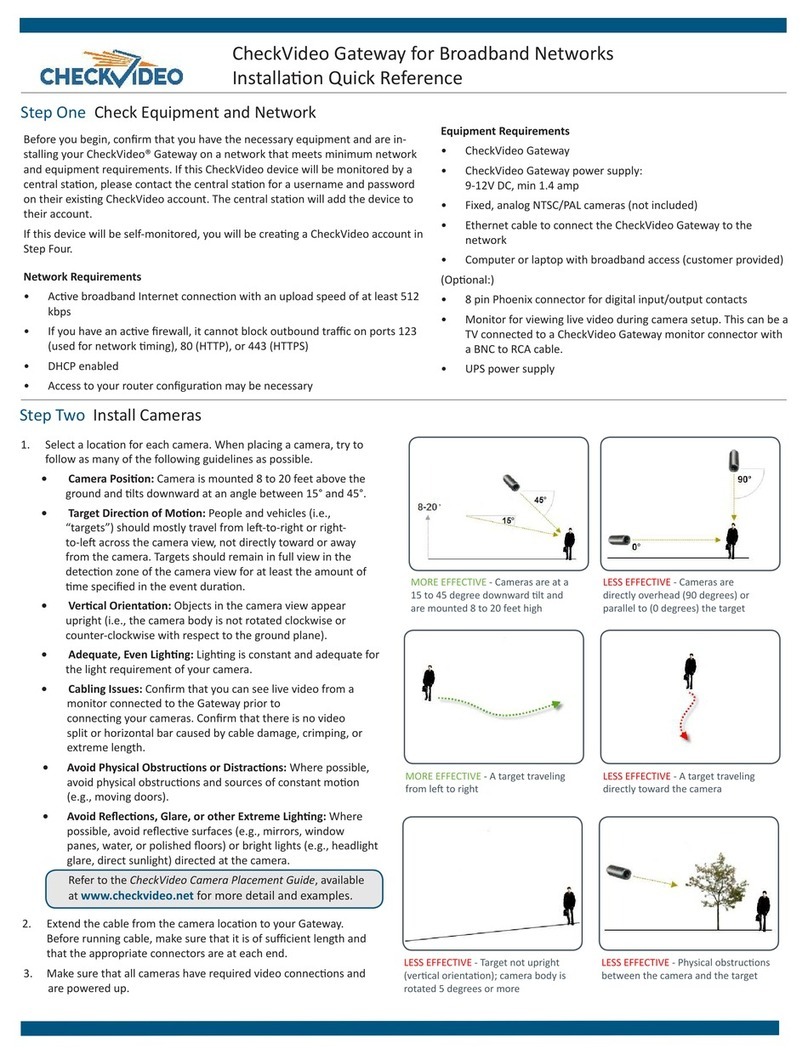
Step Two Camera Placement
Fig. 1 - MORE EFFECTIVE: Cameras
are at a 15 to 45 degree downward
lt and are mounted 8 to 20 feet high.
Fig. 2 - LESS EFFECTIVE: Cameras are
directly overhead (90 degrees) or
parallel to (0 degrees) the target
To opmize event detecon, the cameras you use with CheckVideo
should be placed as follows:
• HEIGHT: Each camera must be installed 8 to 20 feet o the
ground.
• DISTANCE: The distance between camera and target depends
on your camera’s focal length. For example, for a 3.6 mm lens,
if you are mainly detecng people, the distance between the
camera and the people you wish to detect should be 10 to 40
feet. If you are primarily concerned with detecng vehicles, the
range is 20 to 60 feet. See the CheckVideo Camera Placement
Guide for more details and for addional guidelines on
improving your camera placement.
CheckVideo Gateway for Mobile Broadband Networks
Installaon Quick Reference
Step Three Gateway Setup
1. Aach the antennas to the Franklin Module. The antenna with
the white stripe at the base should be on the le when looking
at the front of the device (Fig. 3).
2. Extend the ps of the antennas outward from the Module.
There should be a good distance between the ps, but not so
great that they are at (Fig. 4).
3. Connect the USB cable between the USB port on the Gateway
back panel and the USB port on the front of the Franklin
Module (Fig. 5).
4. Connect each camera’s video cable to a camera port on the
back of the Gateway.
5. Plug in the power to the Franklin Module (12V DC, 1A).
IMPORTANT: Do not use the Gateway’s power supply (which
is larger) to power up the Franklin module. Doing so may
seriously damage the module.
6. Plug in the power to the Gateway (9V, 1.66A).
7. Wait a few minutes for the power light on the front of the
Gateway to ash rapidly.
8. When the ashing slows to one second per pulse, proceed to
the next step in the process (see reverse).
Fig. 3 - Franklin Module antennas
Fig. 5 - USB Port Locaons
White
Stripe
Fig. 4 - Antennas spread outward
Franklin

Note: The only way to see the precise signal strength that the
Gateway actually receives is through the monitor output.
But you can use a Sprint phone to nd the spot in your
facility where you get the best signal.
Step Four 3G Signal Strength (oponal)
Step Seven Device Conguraon
Fig. 8a - A zone, dened by eight end points
(rst point is green; other points are blue)
Fig. 8b - A completed zone
Make sure there is an adequate 3G signal to your Gateway.
You can see the precise signal strength by aaching a monitor to
the Monitor output on the Gateway back panel. The monitor could
be a TV with a BNC to RCA cable.
It may take up to ve minutes for the Received Signal Strength
Indicaon (RSSI) to be displayed on your monitor (Fig. 6).
The RSSI should show a 3G signal strength of greater than -84 to
-86 dBm. Remember that -86 is a negave value, so -85 would be a
beer signal strength than -86, -50 would be much beer, etc.
Cellular signal strength will vary over me. Addionally cellular
network capacity will vary over me. These consideraons must be
taken in to account when deploying a mobile broadband soluon.
1. On the CheckVideo Dashboard, click on Devices >
Congure Device.
2. Select Device: Select the device and video resoluons.
3. Congure Events: Click the Edit buon to create
a zone for a parcular object type. Then use your
mouse to draw the zone by clicking the le mouse
buon wherever you want to dene a point of the
zone. The zone should cover the enre area where
you want to detect an event. Enter a me span, event
type, zone, and duraon and click Add Event buon.
4. Select Nocaon Method - Central Staons: Select a
Central Staon type that should receive alert metadata.
5. Select Nocaon Method - Users: Click the checkbox
next to any user(s) who should receive nocaons
for this camera and their method of nocaon.
6. Click Save.
For more detailed informaon, refer to the CheckVideo Gateway for
Mobile Broadband Networks Installaon Guide via the Partner Login at
www.checkvideo.com. For technical support, contact CheckVideo Customer
Support ([email protected] / 888-992-8433).
© 2013 CheckVideo, LLC.
CheckVideo is a registered trademark of CheckVideo, LLC. All rights reserved.
7CVCGQD000E-04.01
Fig. 6 - RSSI displayed via monitor output
Step Five Create/Access Your Account
1. Go to the CheckVideo Dashboard login page:
portal.checkvideo.net
Click the Start here link to create your account.
If you have an exisng account, log in and skip to the next
secon to register your CheckVideo devices.
2. Complete the User Informaon secon.
3. In the Dene Nocaon Methods secon, for Contact
Informaon enter any email addresses you would like event
Fig. 7 - Enter serial number from the boom of the CheckVideo Gateway device
1. On the CheckVideo Dashboard, click on Devices > Add Device.
2. In the Register Device secon, enter the serial number found on
the boom of the Gateway and a Device Name.
3. Click the Test Device buon to make sure the CheckVideo
Soware Service (CVSS) can communicate with the gateway.
4. (Professional Service only) Authorize service fees.
5. If prompted, update the device rmware.
Step Six Add Gateway Device
nocaons sent to. For nocaons to mobile phones, the address
format will vary by carrier. Choose a Nocaon Format for each
address.
4. In the Billing Preferences, choose your Service opon. If you choose
Central Service, complete the form and CheckVideo Support will contact
you directly.
5. (Professional Service only) Specify method of payment, authorize
service fees, and accept the License Agreement.
Having trouble subming the License Agreement using IE8? Click the
“broken page” icon to turn o compability mode and try again.
Other CheckVideo Gateway manuals
Popular Gateway manuals by other brands

iSimple
iSimple ISFD73 owner's manual

ZyXEL Communications
ZyXEL Communications PRESTIGE 324 user manual
Sollae
Sollae SIG-5450 user manual

Mitsubishi Heavy Industries
Mitsubishi Heavy Industries Superlink SC-WBGW256 Configuration manual
MOKO
MOKO MKGW-mini Series user manual
Cambium Networks
Cambium Networks PTP 650 Series user guide
ZIGBEE
ZIGBEE SmartRoom quick guide
IME
IME Milesight UG63 user guide
Johnson Controls
Johnson Controls VRF Smart Gateway installation instructions
Honeywell
Honeywell SMX quick start guide
IFM Electronic
IFM Electronic CR3146 quick start guide

ZyXEL Communications
ZyXEL Communications ADSL 2+ Security Gateway Specifications
