dacell DN-70 User manual

Ver 1.0
0B
MODEL : DN-70
DIGITAL INDICATOR
USER MANUAL
DACELL CO.,LTD.
Address : 37-9 Cheoksan 5gili, Nami-Myeon,Seowon-gu,
Cheongju-city, Chung-buk
TEL :82-43-260-2242
FAX : 82-43-260-2245
http://www.dacell.com
E-Mail : i[email protected]

1
Contents
1. Features ⋅⋅⋅⋅⋅⋅⋅⋅⋅⋅⋅⋅⋅⋅⋅⋅⋅⋅⋅⋅⋅⋅⋅⋅⋅⋅⋅⋅⋅⋅⋅⋅⋅⋅⋅⋅⋅⋅⋅⋅⋅⋅⋅⋅⋅⋅⋅⋅⋅⋅⋅⋅⋅⋅⋅⋅⋅⋅⋅⋅⋅⋅⋅⋅⋅⋅⋅⋅⋅⋅⋅⋅⋅⋅⋅⋅⋅⋅⋅⋅⋅⋅⋅⋅⋅⋅⋅⋅⋅⋅⋅⋅⋅⋅⋅⋅⋅⋅⋅⋅⋅⋅⋅⋅⋅⋅⋅⋅⋅⋅⋅⋅⋅⋅⋅⋅⋅ 2
1-1. Calibration method ⋅⋅⋅⋅⋅⋅⋅⋅⋅⋅⋅⋅⋅⋅⋅⋅⋅⋅⋅⋅⋅⋅⋅⋅⋅⋅⋅⋅⋅⋅⋅⋅⋅⋅⋅⋅⋅⋅⋅⋅⋅⋅⋅⋅⋅⋅⋅⋅⋅⋅⋅⋅⋅⋅⋅⋅⋅⋅⋅⋅⋅⋅⋅⋅⋅⋅⋅⋅⋅⋅⋅⋅⋅⋅⋅⋅⋅⋅⋅⋅⋅⋅⋅⋅ 2
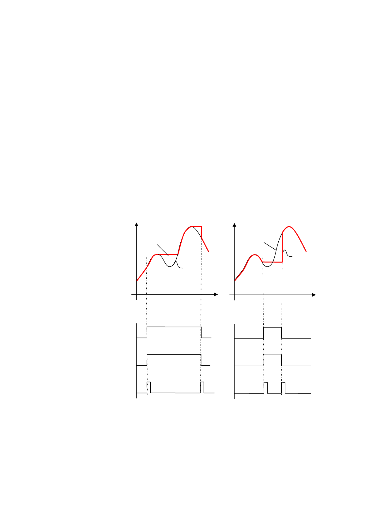
1-2. HOLD & PEAK HOLD ⋅⋅⋅⋅⋅⋅⋅⋅⋅⋅⋅⋅⋅⋅⋅⋅⋅⋅⋅⋅⋅⋅⋅⋅⋅⋅⋅⋅⋅⋅⋅⋅⋅⋅⋅⋅⋅⋅⋅⋅⋅⋅⋅⋅⋅⋅⋅⋅⋅⋅⋅⋅⋅⋅⋅⋅⋅⋅⋅⋅⋅⋅⋅⋅⋅⋅⋅⋅⋅⋅⋅⋅⋅⋅⋅⋅⋅⋅⋅⋅⋅⋅⋅⋅⋅⋅ 2
1-3. Comparison Output ⋅⋅⋅⋅⋅⋅⋅⋅⋅⋅⋅⋅⋅⋅⋅⋅⋅⋅⋅⋅⋅⋅⋅⋅⋅⋅⋅⋅⋅⋅⋅⋅⋅⋅⋅⋅⋅⋅⋅⋅⋅⋅⋅⋅⋅⋅⋅⋅⋅⋅⋅⋅⋅⋅⋅⋅⋅⋅⋅⋅⋅⋅⋅⋅⋅⋅⋅⋅⋅⋅⋅⋅⋅⋅⋅⋅⋅⋅⋅⋅⋅⋅⋅⋅⋅⋅⋅ 2
1-4. Data Back-up ⋅⋅⋅⋅⋅⋅⋅⋅⋅⋅⋅⋅⋅⋅⋅⋅⋅⋅⋅⋅⋅⋅⋅⋅⋅⋅⋅⋅⋅⋅⋅⋅⋅⋅⋅⋅⋅⋅⋅⋅⋅⋅⋅⋅⋅⋅⋅⋅⋅⋅⋅⋅⋅⋅⋅⋅⋅⋅⋅⋅⋅⋅⋅⋅⋅⋅⋅⋅⋅⋅⋅⋅⋅⋅⋅⋅⋅⋅⋅⋅⋅⋅⋅⋅⋅⋅⋅⋅⋅⋅⋅ 2
1-5. Watch dog ⋅⋅⋅⋅⋅⋅⋅⋅⋅⋅⋅⋅⋅⋅⋅⋅⋅⋅⋅⋅⋅⋅⋅⋅⋅⋅⋅⋅⋅⋅⋅⋅⋅⋅⋅⋅⋅⋅⋅⋅⋅⋅⋅⋅⋅⋅⋅⋅⋅⋅⋅⋅⋅⋅⋅⋅⋅⋅⋅⋅⋅⋅⋅⋅⋅⋅⋅⋅⋅⋅⋅⋅⋅⋅⋅⋅⋅⋅⋅⋅⋅⋅⋅⋅⋅⋅⋅⋅⋅⋅⋅⋅⋅⋅⋅⋅⋅⋅⋅⋅⋅⋅⋅⋅⋅⋅⋅⋅⋅⋅⋅⋅⋅⋅⋅⋅⋅ 2
2. Attention ⋅⋅⋅⋅⋅⋅⋅⋅⋅⋅⋅⋅⋅⋅⋅⋅⋅⋅⋅⋅⋅⋅⋅⋅⋅⋅⋅⋅⋅⋅⋅⋅⋅⋅⋅⋅⋅⋅⋅⋅⋅⋅⋅⋅⋅⋅⋅⋅⋅⋅⋅⋅⋅⋅⋅⋅⋅⋅⋅⋅⋅⋅⋅⋅⋅⋅⋅⋅⋅⋅⋅⋅⋅⋅⋅⋅⋅⋅⋅⋅⋅⋅⋅⋅⋅⋅⋅⋅⋅⋅⋅⋅⋅⋅⋅⋅⋅⋅⋅⋅⋅⋅⋅⋅⋅⋅⋅⋅⋅⋅ 3
2-1. Attention for installation ⋅⋅⋅⋅⋅⋅⋅⋅⋅⋅⋅⋅⋅⋅⋅⋅⋅⋅⋅⋅⋅⋅⋅⋅⋅⋅⋅⋅⋅⋅⋅⋅⋅⋅⋅⋅⋅⋅⋅⋅⋅⋅⋅⋅⋅⋅⋅⋅⋅⋅⋅⋅⋅⋅⋅⋅⋅⋅⋅⋅⋅⋅⋅⋅⋅⋅⋅⋅⋅⋅⋅⋅⋅⋅⋅⋅⋅⋅⋅⋅⋅⋅⋅⋅⋅⋅⋅⋅⋅⋅⋅⋅ 3
2-2. Attention for use ⋅⋅⋅⋅⋅⋅⋅⋅⋅⋅⋅⋅⋅⋅⋅⋅⋅⋅⋅⋅⋅⋅⋅⋅⋅⋅⋅⋅⋅⋅⋅⋅⋅⋅⋅⋅⋅⋅⋅⋅⋅⋅⋅⋅⋅⋅⋅⋅⋅⋅⋅⋅⋅⋅⋅⋅⋅⋅⋅⋅⋅⋅⋅⋅⋅⋅⋅⋅⋅⋅⋅⋅⋅⋅⋅⋅⋅⋅⋅⋅⋅⋅⋅⋅⋅⋅⋅⋅⋅⋅⋅ 3
3. Specification ⋅⋅⋅⋅⋅⋅⋅⋅⋅⋅⋅⋅⋅⋅⋅⋅⋅⋅⋅⋅⋅⋅⋅⋅⋅⋅⋅⋅⋅⋅⋅⋅⋅⋅⋅⋅⋅⋅⋅⋅⋅⋅⋅⋅⋅⋅⋅⋅⋅⋅⋅⋅⋅⋅⋅⋅⋅⋅⋅⋅⋅⋅⋅⋅⋅⋅⋅⋅⋅⋅⋅⋅⋅⋅⋅⋅⋅⋅⋅⋅⋅⋅⋅⋅⋅⋅⋅⋅⋅⋅⋅⋅⋅⋅⋅⋅⋅⋅⋅⋅⋅⋅⋅⋅⋅⋅⋅⋅⋅⋅⋅⋅⋅⋅⋅⋅⋅⋅⋅ 4
4. Front Panel ⋅⋅⋅⋅⋅⋅⋅⋅⋅⋅⋅⋅⋅⋅⋅⋅⋅⋅⋅⋅⋅⋅⋅⋅⋅⋅⋅⋅⋅⋅⋅⋅⋅⋅⋅⋅⋅⋅⋅⋅⋅⋅⋅⋅⋅⋅⋅⋅⋅⋅⋅⋅⋅⋅⋅⋅⋅⋅⋅⋅⋅⋅⋅⋅⋅⋅⋅⋅⋅⋅⋅⋅⋅⋅⋅⋅⋅⋅⋅⋅⋅⋅⋅⋅⋅⋅⋅⋅⋅⋅⋅⋅⋅⋅⋅⋅⋅⋅⋅⋅⋅⋅⋅⋅⋅⋅⋅⋅⋅ 5
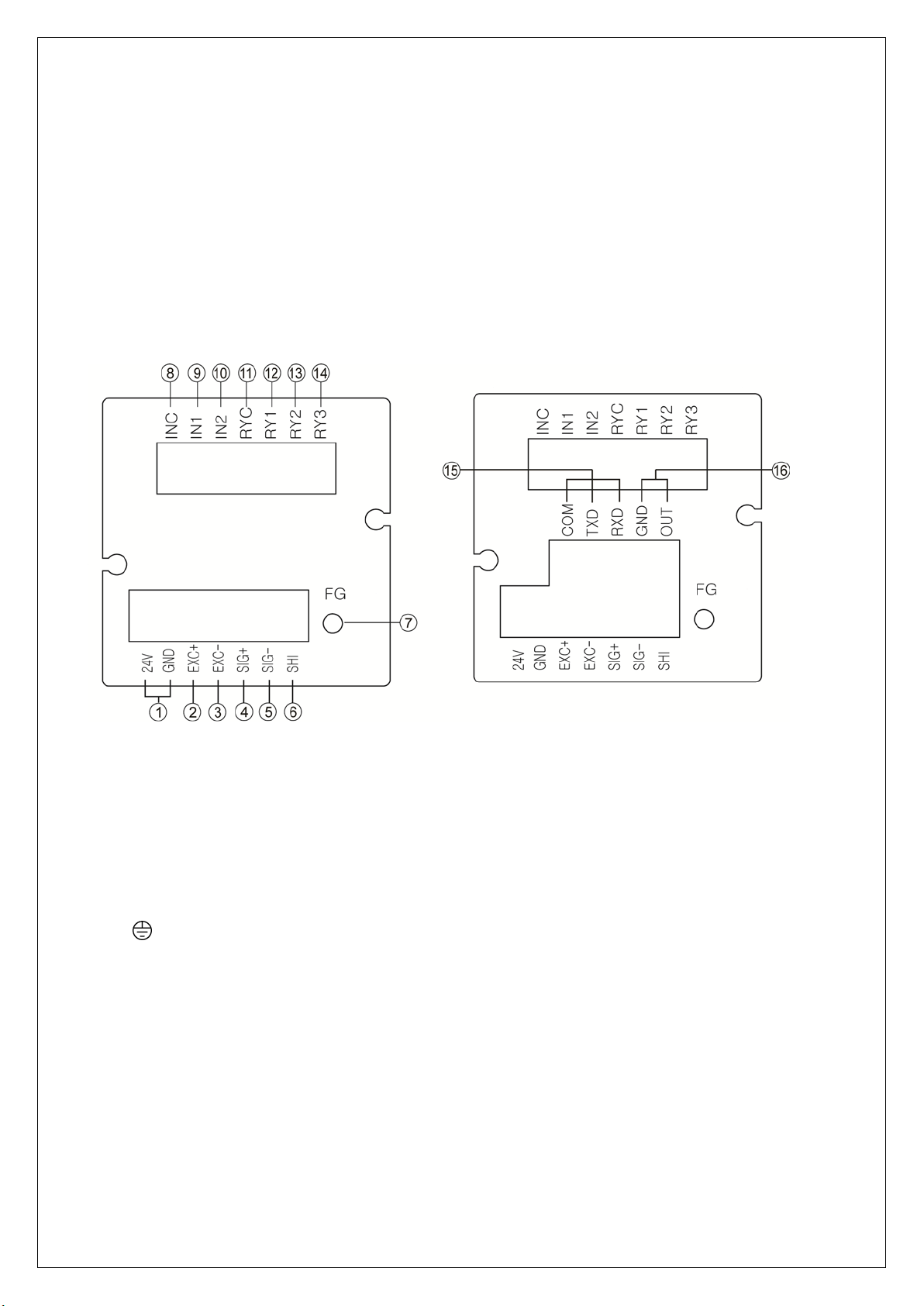
5. Rear Panel ⋅⋅⋅⋅⋅⋅⋅⋅⋅⋅⋅⋅⋅⋅⋅⋅⋅⋅⋅⋅⋅⋅⋅⋅⋅⋅⋅⋅⋅⋅⋅⋅⋅⋅⋅⋅⋅⋅⋅⋅⋅⋅⋅⋅⋅⋅⋅⋅⋅⋅⋅⋅⋅⋅⋅⋅⋅⋅⋅⋅⋅⋅⋅⋅⋅⋅⋅⋅⋅⋅⋅⋅⋅⋅⋅⋅⋅⋅⋅⋅⋅⋅⋅⋅⋅⋅⋅⋅⋅⋅⋅⋅⋅⋅⋅⋅⋅⋅⋅⋅⋅⋅⋅⋅⋅⋅⋅⋅⋅⋅⋅⋅ 6
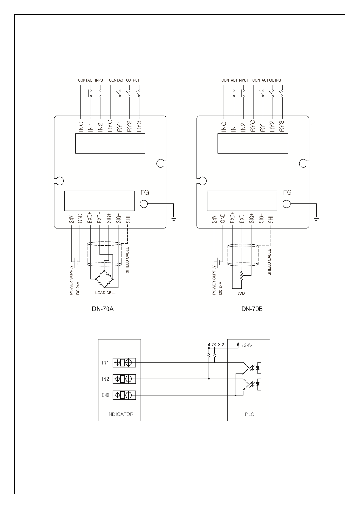
6. Wiring Diagram ⋅⋅⋅⋅⋅⋅⋅⋅⋅⋅⋅⋅⋅⋅⋅⋅⋅⋅⋅⋅⋅⋅⋅⋅⋅⋅⋅⋅⋅⋅⋅⋅⋅⋅⋅⋅⋅⋅⋅⋅⋅⋅⋅⋅⋅⋅⋅⋅⋅⋅⋅⋅⋅⋅⋅⋅⋅⋅⋅⋅⋅⋅⋅⋅⋅⋅⋅⋅⋅⋅⋅⋅⋅⋅⋅⋅⋅⋅⋅⋅⋅⋅⋅⋅⋅⋅⋅⋅⋅⋅⋅⋅⋅ 8
7. Components & Function ⋅⋅⋅⋅⋅⋅⋅⋅⋅⋅⋅⋅⋅⋅⋅⋅⋅⋅⋅⋅⋅⋅⋅⋅⋅⋅⋅⋅⋅⋅⋅⋅⋅⋅⋅⋅⋅⋅⋅⋅⋅⋅⋅⋅⋅⋅⋅⋅⋅⋅⋅⋅⋅⋅⋅⋅⋅⋅⋅⋅⋅⋅⋅⋅⋅⋅⋅⋅⋅⋅⋅⋅⋅⋅⋅⋅⋅⋅⋅⋅⋅⋅⋅⋅⋅⋅⋅⋅⋅⋅⋅⋅⋅⋅⋅⋅⋅⋅⋅⋅⋅⋅⋅⋅⋅ 9
7-1. How to use Hold mode ⋅⋅⋅⋅⋅⋅⋅⋅⋅⋅⋅⋅⋅⋅⋅⋅⋅⋅⋅⋅⋅⋅⋅⋅⋅⋅⋅⋅⋅⋅⋅⋅⋅⋅⋅⋅⋅⋅⋅⋅⋅⋅⋅⋅⋅⋅⋅⋅⋅⋅⋅⋅⋅⋅⋅⋅⋅⋅⋅⋅⋅⋅⋅⋅⋅⋅⋅⋅⋅⋅⋅⋅⋅⋅ 9
7-2. How to use comparison output function ⋅⋅⋅⋅⋅⋅⋅⋅⋅⋅⋅⋅⋅⋅⋅⋅⋅⋅⋅⋅⋅⋅⋅⋅⋅⋅⋅⋅⋅⋅⋅⋅⋅⋅⋅⋅⋅⋅⋅⋅⋅⋅⋅ 10
8. Setting mode ⋅⋅⋅⋅⋅⋅⋅⋅⋅⋅⋅⋅⋅ ⋅⋅⋅⋅ ⋅⋅⋅⋅ ⋅⋅⋅⋅ ⋅⋅⋅⋅ ⋅⋅⋅⋅⋅⋅⋅⋅ ⋅⋅⋅⋅⋅⋅⋅⋅⋅⋅⋅⋅⋅⋅⋅ ⋅⋅⋅⋅ ⋅⋅⋅⋅⋅⋅⋅⋅⋅⋅⋅⋅⋅⋅⋅ ⋅⋅⋅⋅ ⋅⋅⋅⋅ ⋅⋅⋅⋅ ⋅⋅⋅⋅ ⋅⋅⋅⋅ ⋅⋅⋅⋅ 12
8-1. Types of Setting mode & Set-up ⋅⋅⋅⋅⋅⋅⋅⋅⋅⋅⋅⋅⋅⋅⋅⋅⋅⋅⋅⋅⋅⋅⋅⋅⋅⋅⋅⋅⋅⋅⋅⋅⋅⋅⋅⋅⋅⋅⋅⋅⋅⋅⋅⋅⋅⋅⋅⋅⋅⋅⋅⋅⋅⋅⋅⋅⋅⋅⋅⋅⋅⋅⋅⋅⋅⋅⋅⋅⋅⋅⋅⋅⋅⋅⋅⋅⋅ 12
8-2. Function mode (Function Set-up) ⋅⋅⋅⋅⋅⋅⋅⋅⋅⋅⋅⋅⋅⋅⋅⋅⋅⋅⋅⋅⋅⋅⋅⋅⋅⋅⋅⋅⋅⋅⋅⋅⋅⋅⋅⋅⋅⋅⋅⋅⋅⋅⋅⋅⋅⋅⋅⋅⋅⋅⋅⋅⋅⋅⋅⋅⋅⋅ 13
8-3. Digital calibration (Calibration by sensor output value) ⋅⋅⋅⋅⋅⋅⋅⋅⋅⋅⋅⋅⋅⋅⋅⋅⋅⋅⋅⋅⋅⋅⋅⋅⋅⋅⋅ 20
8 - 4. Real-weight Calibration ⋅⋅⋅⋅⋅⋅⋅⋅⋅⋅⋅⋅⋅⋅⋅⋅⋅⋅⋅⋅⋅⋅⋅⋅⋅⋅⋅⋅⋅⋅⋅⋅⋅⋅⋅⋅⋅⋅⋅⋅⋅⋅⋅⋅⋅⋅⋅⋅⋅⋅⋅ 21
8-5. Data Back-up & Restore ⋅⋅⋅⋅⋅⋅⋅⋅⋅⋅⋅⋅⋅⋅⋅⋅⋅⋅⋅⋅⋅⋅⋅⋅⋅⋅⋅⋅⋅⋅⋅⋅⋅⋅⋅⋅⋅⋅⋅⋅⋅⋅⋅⋅⋅⋅⋅⋅⋅⋅⋅⋅⋅⋅⋅⋅⋅⋅ 22
8-6. Lock Set-up ⋅⋅⋅⋅⋅⋅⋅⋅⋅⋅⋅⋅⋅⋅⋅⋅⋅⋅⋅⋅⋅⋅⋅⋅⋅⋅⋅⋅⋅⋅⋅⋅⋅⋅⋅⋅⋅⋅⋅⋅⋅⋅⋅⋅⋅⋅⋅⋅⋅⋅⋅⋅⋅⋅⋅⋅⋅⋅⋅⋅⋅⋅⋅⋅⋅⋅⋅⋅⋅⋅⋅⋅⋅⋅⋅⋅⋅⋅⋅⋅⋅⋅⋅⋅⋅⋅⋅⋅⋅⋅ 23
9. Product Inspection ⋅⋅⋅⋅⋅⋅⋅⋅⋅⋅⋅⋅⋅⋅⋅⋅⋅⋅⋅⋅⋅⋅⋅⋅⋅⋅⋅⋅⋅⋅⋅⋅⋅⋅⋅⋅⋅⋅⋅⋅⋅⋅⋅⋅⋅⋅⋅⋅⋅⋅⋅⋅⋅⋅⋅⋅⋅⋅⋅⋅⋅⋅⋅⋅⋅⋅⋅⋅⋅⋅⋅⋅⋅⋅⋅⋅⋅⋅⋅⋅⋅⋅⋅⋅⋅⋅⋅⋅⋅⋅⋅⋅⋅⋅⋅⋅⋅⋅⋅⋅⋅⋅⋅ 24
10. OPTION (OP-02, OP-03)
Option 02 (RS232C) ⋅⋅⋅⋅⋅⋅⋅⋅⋅⋅⋅⋅⋅⋅⋅⋅⋅⋅⋅⋅⋅⋅⋅⋅⋅⋅⋅⋅⋅⋅⋅⋅⋅⋅⋅⋅⋅⋅⋅⋅⋅⋅⋅⋅⋅⋅⋅⋅⋅⋅⋅⋅⋅⋅⋅⋅⋅⋅⋅⋅⋅⋅⋅⋅⋅⋅⋅⋅⋅⋅⋅⋅⋅⋅⋅⋅⋅⋅⋅⋅⋅⋅⋅⋅⋅⋅⋅⋅⋅⋅⋅⋅⋅⋅⋅⋅⋅⋅⋅⋅⋅⋅⋅ 25
Option 03 (RS485) ⋅⋅⋅⋅⋅⋅⋅⋅⋅⋅⋅⋅⋅⋅⋅⋅⋅⋅⋅⋅⋅⋅⋅⋅⋅⋅⋅⋅⋅⋅⋅⋅⋅⋅⋅⋅⋅⋅⋅⋅⋅⋅⋅⋅⋅⋅⋅⋅⋅⋅⋅⋅⋅⋅⋅⋅⋅⋅⋅⋅⋅⋅⋅⋅⋅⋅⋅⋅⋅⋅⋅⋅⋅⋅⋅⋅⋅⋅⋅⋅⋅⋅⋅⋅⋅⋅⋅⋅⋅⋅⋅⋅⋅⋅⋅⋅⋅⋅⋅⋅⋅⋅⋅ 27

2
1. Features
We thank you for using our product. Please refer to this manual or contact our office if
you find any problems during using our product.
This product is an indicator that emplifies the micro voltage signals from each sensor
and display in digital. It is mainly used to measure physical quantities of the items using
strain guage such as loadcell, pressure sensor, displacement sensor and torque sensor.
This product has the following special features.
1-1. Calibration Method
2 types of calibration systems are adopted. Calibration by actual load (standard
weight) and calibration by rated output of sensor (mV/V).
1-2. Hold 및Peak Hold
You can choose peak hold and sample hold as per your need.
1-3. Comparison Output
You can do set-up the maxium and lower limit value by the keys on the front panel
and print with contact point signal of the rear panel.
1-4. Data Back-up
All the set-up values will be memorized on the flash memory so the inputted data can
be saved and no need to do the re-setting even in case of the interruption of the
electric power or power disconnection.
1-5. Watch dog
This function is for automatic reset in case the system is stopped due to the external
factors such as noise.

3
2. Attention
For the efficient and safe use, please carefully read and be fully aware of the following
details before using this product.
It is strictly forbidden to use this product for any other purpose of use or to attempt to
make any alteration on this product.
2-1. Attention for installation
•Please keep it out of wet places.
•Do not set it up near vibration & impulse, high temperature and humidity.
Keep it out of the direct rays of the sun. Set it up where there is less dust, and Keep it
out of direct air including salt and ion.
•Do not use when there is inflammable gas or heavy machinery, and smog.
•Ground earth-terminal ( ).
•Make wire separately from power system wiring and noise wiring.
•Make sure the use of 4 line sealed cable as a sensor cable.
Too long cable leads to measurement error due to wiring resistance (around
10meters).
2-2. Attention for use
During calibration, Do not input free-load state and real-weight load until it becomes
stable. Pressing Enter Key in unstable condition leads to calibration error.
Do not press any Key in use at one's discretion. Please refer to 7. Setting-up mode
for the function and method of Key.

4
3. Specification
•Available sensor
DN-70 : Strain Gauge sensor
•SIGNAL
DN-70 : 1 ~ 3mV/V
•EXCITATION : 5V
•Upper limit Display : -19999 ~ +99999
•A/D Converter : 24bit
•D/A Converter : 16bit
•Temperature Characteristic (Amp Characteristic)
Zero : 0.5μV/℃
Span : 50ppm/℃
•Front Panel
Measured value display :7segment
Status display : Red LED 5pcs
Key Switch : 4pcs
•Comparison output : Upper limit(HI), Lower limit(LO), Normal(OK) Output
Contact Capacity - AC 250V 3A
• Temperature Range: -10℃∼60℃, less than 80% RH (no dewing.)
•External dimension : 48 × 48 × 128 mm (W × H × D)
•Panel cutting size : 45.5 × 45.5 mm
•Weight : About 280g
•Power Supply : DC 24V
•Option : RS232C (OP-02), RS485 (OP-03)
Analog out: 0 ~ ±10V or 4 ~ 20mA

5
4. Front panel
①HI, LO Indication LED: LED will be lighted when measured value exceeds the setting
value.
②HOLD Indication LED: This LED will be lighted when the measured value is on Hold.
③MOD : Measured value stable (on), unstable (off) indication
④Measured value Indication: It indicates the measured value and each setting value.
⑤
Measruing Mode : Once this Key is pressed for more than 1 second, the current
measuring value will be Zero (0) and the Analog output will be 0V (4mA) as well.
SET-UP Mode : Once this is pressed on the Function Set-up Mode, you will
return to the measuring mode.
⑥
Measuring Mode : Once this Key is pressed, the lower limit setting value will be
displayed and this value also can be changed.
SET-UP Mode : The location of row for the number flickering can be moved.
⑦
Measuring Mode : Once this Key is pressed, the upper limit setting value will be
displayed and the value can be changed.
SET-UP Mode : The flickering number will be increased by 1 and 1.
⑧
Measuring Mode : Once this Key is pressed, HOLD will be selected and once this
key is pressed again, HOLD will be cancelled.
SET-UP Mode : Save each set-up value.

6
5. Rear Panel
Please check the location of terminal and its use. While the projected button is being
pressed, please insert the cable into the lower hole completely. As soon as you release
the button, the connection will be completed. At the point, please slightly pull the calbe
and check whether the cable is come off or not.
(The most suitable calbe is Φ0.5~1. Linking cable must be brazing or used with 1
terminal)
①24V : DC24V (Main Power)
②EXC+ : Sensor Supply Voltage + Connection Terminal
③EXC- : Sensor Supply Voltage + Connection Terminal
④SIG+ : Sensor Ouput Signal + Connection Terminal
⑤SIG- : Sensor Output Signal –Connection Terminal
⑥GND : SHIELD connection terminal of sensor
⑦: Ground Terminal (as an independent ground connection.)
⑧INC : External Input Common Terminal
⑨IN1 : External HOLD Input Terminal
⑩IN2 : External ZERO Input Terminal
⑪RYC : RELAY Common Terminal
⑫RY1 : RELAY1(Lower Limit) Output Terminal
⑬RY2 : RELAY2 (Upper Limit) Output Terminal
⑭RY3 : RELAY3( Normal) Output Terminal (OK )

7
※OPTION
⑮GND, TXD, RXD : RS232C SERIAL INTERFACE Terminal
(RS485 : TXD -> TX+, RXD -> TX-)
○
16E
AGND, OUT : Analog out Terminal (DC ±10V or DC 4~20mA)
◀Attention▶
1. When wiring, please pull out the power plug. (Main power supply)
2. Please use the thick calbe for ground terminal ( ) so that you can avoid any trouble
due to the impulse voltage or surge. If possible, please keep it as an independent
ground.
(This must be used in the area with heavy noise. If the ground is made with other
device, it will be affected by noise.)
3. Please check the function of the terminal before you do the wiring so that you can
prevent any malfunction in advance.
4. Manufacture will be relieved of its responsibility for any damge or injury due to the
disassembly and alteration made without any agreement. Also, no A/S will be made.

8
6. Wiring Diagram
<Wiring Diagram>
<Example - External Input PLC Connection>

9
7. Components & Function
7-1. How to use Hold mode
Hold mode is largely divided into Peak Hold and Sample Hold. Please select Peak or
Sample. To input Hold, you can use Hold key on the front panel or external input. For
the operation method, please refer to the drawing below.
1) Peak Hold : To Hold the maxium value among the measured values.
Peak hold mode : It is to hold and display the maximum value of (+) direction.
Absolute peak hold mode : It is to hold and display the maximum value of the
absolute value (+/-).
2) Sample hold : It is to hold and display the value at the time of Hold signal input
among the measured values.
On
Off
On
Off
On
off
① − :
sensor input
value
②
−
: Display value &
analog output value
Measured value
time
①
②
Measured value
time
①
②
<Peak HOLD> <Sample HOLD>
Front panel HOLD LED
External
HOLD input termanal
Front panel HOLD Key

10
7-2. How to use comparison ouput function
For comparison output function, there are 3 different modes such as Decision, High
limit, Low limit. It displays through the relay of rear panel comparing each setup value.
On High limit and Low limit mode, Hysteresis can be used.
To set up upper limit (High) and lower limit(Low), please use the key on the front panel.
1) Decision mode : Measured Value ≤Lower limit setup value ⇒RY1 ON (LO)
Measured Value ≥Upper limit setup value ⇒RY2 ON (HI)
Lower limit setup value < Measured value < Upper limit setup value ⇒RY3 ON(OK)
2) High limit mode : Measured Value ≥RY1 setup value ⇒RY1 ON
Measured Value ≥RY2 setup value ⇒RY2 ON
Measured Value ≥RY3 setup value ⇒RY3 ON
Measured Value < RY1 setup value –Hysteresis value⇒RY1 OFF
Measured Value < RY2 setup value - Hysteresis value⇒RY2 OFF
Measured Value < RY3 setup value –Hysteresis value⇒RY3 OFF
3) Low limit mode : Measured Value ≤RY1 setup value ⇒RY1 ON
Measured Value ≤RY2 setup value ⇒RY2 ON
Measured Value ≤RY3 setup value ⇒RY3 ON
Measured Value > RY1 setup value + Hysteresis value⇒RY1 OFF
Measured Value > RY2 setup value + Hysteresis value⇒RY2 OFF
Measured Value > RY3 setup value + Hysteresis value⇒RY3 OFF

11

12
8. Setting Modes
8-1. Types of Setting mode & Set-up
For Setting mode, there are 3 different types of mode such as Function mode, Digital
calibration mode, Actual load calibration mode.
Mesuring mode
While key is being
Press, press key
Function mode
①
Digital calibration
mode
②
③
Actual load
calibration mode
①Function mode
Acess to each function setup mode. Please refer 8-2 function mode.
②Digital calibration mode
It is to calibrate into the sensor’s output value. No need to prepare for the actual
load (stand weight). Please refer 8-3 how to calibrate.
③Actual load calibration mode
It is to calibrate by adding the actual load (standard weight or the load you know).
Please refer 8-4 how to calibrate.

13
8-2. Function mode
1) How to set function
Measuring mode
While key is being
Press, press key

14
2) How to set RELAY data
①Decision mode (Decision mode: mode 0)
②Limit mode (Low & High limit mode: mode 1 ~ 2)
Measuring mode
Press key
Input
value

15
# Function mode list #
Name
Function
Setting
출고시 기준설정값
F-01 Decimal point 0, 1, 2, 3 1
F-02 Division 1, 2, 5, 10, 20, 50 1
F-03 Display filter 1, 2, 5, 10, 20, 50, 100 20
F-04 Hold mode Sample hold, Peak hold, Absolute peak hold
Peak hold
F-05 Comparison mode Decision, High limit, Low limit Decision
F-06 Hysteresis 0 ~ 99 0
F-07 DAC zero V_05V, V_10V, V02A, V_42A,
b_05V, b_10V, b_02A, b_42A V_10V
F-08 DAC capacity -19999 ~ +99999 10000
F-09 ID Number 0 ~ 32 0
F-10 Baud rate 2400, 4800, 9600, 19200, 38400, 57600 9600
F-11 Auto zero tracking 0 ~ 99 0
F-12 Auto zero tracking time
0.0 ~ 5.0 sec 0.0
F-13 Force unit Kg(kg/㎠), N, ℓb, bar, MPa Kg
F-14 Key disabling Zero key, Lo key, Hi key, Hold key 0000
F-50 Offset (Base) -19999 ~ +10000 0
F-51 Direction 0, 1, 2 0
※F-07 (OPTION, Analog out)
Display data Setting
V_05V 0 ~ ±5V Output
V_10V 0 ~ ±10V Output
V_02A 0 ~ 20mA Output
V_42A 4 ~ 20mA Output
b_05V 2.5V ~ 5V Output 2.5V ~ 5V)
b_10V 5V ~ 10V Output (0 ~ 5V ~ 10V)
b_02A 10mA ~ 20mA Output (0mA ~ 10mA ~ 20mA)
b_42A 12mA ~ 20mA Output (4mA ~ 12mA ~ 20mA)

16
F-01. Decimal point (Decimal point Set-up)
(Standard setup value: 1)
Display data Setting
0 00000 : No decimal point
1 0000.0 : One decimal place
2 000.00 : Two decimal places
3 00.000 : Three decimal places
F-02. Division (Minimum display unit setup)
(Standard setup value: 1)
Display data Setting
1 Displayed In 1 (0, 1, 2, 3, 4 …….)
2 Displayed in 2 (0, 2, 4, 6, 8 …….)
5 Displayed in 5 (0, 5, 10, 15 …….)
10 Displayed in 10 (0, 10, 20, 30 …….)
20 Displayed in 20 (0, 20, 40, 60 …….)
50 Displayed in 50 (0, 50, 100, 150 …….)
F-03. Display filter (Display speed setup)
(Standard setup value: 16)
Display data Setting
1 Past
Slow
2
5
10
20
50
100
F-04. Hold mode
(Standard setup value: 1)
Display data Setting
0 Sample Hold : To hold the displa
y value at the time of Hold
signal input.
1 Peak Hold (+)
:
To hold the maximum value of display values
during Hold signal input.
2 Absolute Peak Hold(+/-) :
To hold the maximum absolute value of display
values during Hold signal input.

17
F-05. Comparision mode (Comparision output mode setup)
(Standard setup value: 0)
Display data Setting
0 Decision mode : Relay RY1(Lo), RY2(Hi), RY3(Ok) Output
1 High limit mode : Relay RY1, RY2, RY3 Output
2 Low limit mode : Relay RY1, RY2, RY3 Output
F-06. Hysteresis
(Standard setup value: 00)
Display data Setting
00 00 : Hysteresis not used
~
99 01 ~99 : Hysteresis used (Decision mode is not applied)
F-08. DAC zero (Analog Outupt value setup)
(Standard setup value : 10000)
Display data Setting
-19999 Analog output capacity set-up
<If Setting value 10000>
Display
data
F-07 setting data
V_05V V_10V V_02A V_42A b_05V b_10V b_02A b_42A
-10000
-5V -10V 0 4mA 0 0 0 4mA
0 0 0 0 4mA 2.5V 5V 10mA 12mA
10000 +5V +10V 20mA 20mA 5V 10V 20mA 20mA
1
~
+99999
F-09. ID Number (Communication Device Number setup)
(Standard setup value: 00)
Display data
Setting
00 00
: Device number is not set-up(Stream mode:always transmit data )
~
32 01 ~32
: Device number is set-up(Command mode:Transmit data by command)

18
F-10. Baud rate & Print (Communication Speed Setup)
(Standard setup value: 9.60)
Display data Setting Stream mode Command mode
2.40 2400 bps O O
4.80 4800 bps O O
9.60 9600 bps O O
19.20 19200 bps O X
PRINT PRINT DATA OUT (PT-100) - -
F-11. Auto zero tracking (Auto zero operation range setup)
(Standard setup value: 00)
Display data Setting
00 00 : Auto zero is not used
~
99 01 ~99 : Set up the operation range of auto zero
F-12. Auto zero tracking time (Auto Zero tracking time setup)
(Standard setup value: 0.0)
Display data Setting
00 0.0 : Auto zero is not used
~
5.0 0.1 ~5.0 : set up the auto zero operation time (0.1 ~ 5.0 sec)
F-13. Force unit (Conversion unit set up)
(Standard setup value: 0)
Display data Setting
0 kg.f kg/㎠
1 N kgf × 9.8 - -
2 ℓb kgf × 2.2 - -
3 - - Bar kg/㎠× 0.98
4 - - MPa kg/㎠× 0.098
Note) During calibration, set up the unit you want after calibrating it into Kg.

19
F-14. Key disabling (Front key locking set up)
(Standard setup value: 0000)
Display data Setting
0 0 0 0
Hold key Lock (1), Release (0)
Hi key Lock (1), Release (0)
Lo key Lock (1), Release (0)
Zero key Lock (1), Release (0)
<Set-up example>
1001 : Zero & Hold key Lock, Hi and Lo key Release
F-50.
Offset (Base value
)
(Standard setup value : 00000)
Display data Setting
-19999 If set to Base value and is a Zero signal , Base value is registered.
(When Base value 10.00 , the display is 10.00 if you press ZERO button)
When setting the reference value, t
he comparison output operation is
not based on whether the existing display data reaches the upper limit
(RY2) or lower limit (RY1) setting value.
Based on the setting value of F-50, upper RY3,
upper limit (RY2) and
lower limit (RY1) set values are operated.
~
+10000
F-51. Direction (
Direction setting, mark reverse
)
(Standard setup value : 0)
Display data Setting
0 0 : Positive mark
1 1 : Negative mark
(Please confirm direction, Base input value at mark alteration)
2 Display as absolute value
Table of contents
Other dacell Measuring Instrument manuals

dacell
dacell PDN-10 User manual

dacell
dacell DN-711A User manual

dacell
dacell DN-10W User manual

dacell
dacell SM110 User manual

dacell
dacell DN-40W User manual

dacell
dacell DN-10 User manual

dacell
dacell DN500N User manual

dacell
dacell DN-300 User manual

dacell
dacell DN-330 User manual

dacell
dacell DN-100 User manual