Chen Hsong CDC-2000 Quick start guide

CDC-2000 Operational Manual
1. CDC-2000 COMPUTER PANEL OVERVIEW-------------------------------------------------1
1.1.COMPUTER PANEL DESCRIPTION-------------------------------------------------------------------------1
1.2. MENITOR QPERATIONAL KEYS---------------------------------------------------------------------------2
1.3. NUMBER OPERATIONAL KEYS-----------------------------------------------------------------------------4
1.4. COMBINED OPERATIONAL KEYS--------------------------------------------------------------------------6
1.5. POWER OPERATIONAL KEYS-------------------------------------------------------------------------------6
1.6. MOTON OPERATIONAL KEYS-------------------------------------------------------------------------------7
1.7. CHART OPERATIONAL KEYS-------------------------------------------------------------------------------7
1.8.FORMING STATUS OPERATIONAL KEYS------------------------------------------------------------------12
2. COMPUTER CHART OVERVIEW-------------------------------------------------------------------13
2.1. SYSTEM INITIAL CHART-----------------------------------------------------------------------------------13
2.2. MANUAL OPERATION SETTINTG--------------------------------------------------------------------------14
2.3. AUTO PERATION SETTING---------------------------------------------------------------------------------15
2.4. MONITOR TIME CHART------------------------------------------------------------------------------------17
2.5. SET UP FOR BOOSTER CYLINDER MOLD CLOSING AND OPENING-----------------------------------19
2.6. SETUP FOR HIGH PRESSURE CYLINDER AND SPLIT NUTS--------------------------------------------32
2.7. EJECTOR SETUP--------------------------------------------------------------------------------------------38
2.8. SORE PULL SETUP------------------------------------------------------------------------------------------41
2.9. UNSCREW SETUP-------------------------------------------------------------------------------------------44
2.10. AIR - BLOW SETUP ---------------------------------------------------------------------------------------48
2.11. MOLD THICKNESS AND CLAMPING FORCE SETUP---------------------------------------------------49
2.12. LUBRICATION SETUP-------------------------------------------------------------------------------------57
2.13. INJECTION SETUP----------------------------------------------------------------------------------------58
2.14. PLASTICIZING AND FEEDING SETUP------------------------------------------------------------------62
2.15. INJECTION CARRIAGE SETUP--------------------------------------------------------------------------65
2.16. SPEED AND PRESSURE CURVE--------------------------------------------------------------------------66
2.17. THEORETICAL INJECTION VOLUME CURVE----------------------------------------------------------67
2.18. THEORETICAL INJECTION SPEED CURVE-------------------------------------------------------------68
2.19. THEORETICAL INJECTION PRESSURE CURVE--------------------------------------------------------69
2.20. PROMPT SETTING CHART-------------------------------------------------------------------------------70
2.21. TEMPERATURE SETUP-----------------------------------------------------------------------------------73
2.22. TEMPERATURE SETTING CHART-----------------------------------------------------------------------75
2.23. TEMPERATURE TIMING SETUP-------------------------------------------------------------------------76
2.24. TEMPERATURE CURVE OF T1---------------------------------------------------------------------------77
2.25. TEMPERATURE CURVE OF T2---------------------------------------------------------------------------78
I

CDC-2000 Operational Manual
2.26. TEMPERATURE CURVE OF T3---------------------------------------------------------------------------79
2.27. TEMPERATURE CURVE OF T4---------------------------------------------------------------------------80
2.28. TEMPERATURE CURVE OF T5---------------------------------------------------------------------------81
2.29. TEMPERATURE CURVE OF ------------------------------------------------------------------------------82
2.30. TEMPERATURE CURVE OF TC--------------------------------------------------------------------------83
2.31. MOULD NUMBER SETTING-------------------------------------------------------------------------------84
2.32.SPARE COUNTER SETUP-----------------------------------------------------------------------------------88
2.33.QUALITY RECORD CHART--------------------------------------------------------------------------------90
2.34.SPC DISPLAY CHART---------------------------------------------------------------------------------------92
2.35.QUALITY CURVE DISPLAY CHART-----------------------------------------------------------------------93
2.36.PROGRAM MONITORING---------------------------------------------------------------------------------94
2.37.RELAY MONITORING--------------------------------------------------------------------------------------95
2.38.INPUT NODE MONITORING OF COMPUTER-------------------------------------------------------------99
2.39.OUTPUT NODE MONITORING----------------------------------------------------------------------------111
2.40.FUNCTION SELECTION SETUP--------------------------------------------------------------------------123
2.41.SPARE SPEED AND PRESSURE SETUP------------------------------------------------------------------127
2.42.SPARE COUNTER SETUP---------------------------------------------------------------------------------133
2.43.SPARE TIMER UNIT DESCRIPTION---------------------------------------------------------------------137
2.44.RECORED CHART OF BREAKDOWN--------------------------------------------------------------------141
2.45.RESTORING OPERATIONAL CHART OF OPTICAL METEN-------------------------------------------143
2.46.PERIPHERAL AND CIPHER SETTING CHART----------------------------------------------------------145
2.47.DISPLAY CHART OF PRODUCTIVE INFORMATION---------------------------------------------------147
2.48.RECORD CHART OF PARAMETRIC VARIATION-------------------------------------------------------148
3 . ALARM INFORMATION OVERVIEW-------------------------------------------------------------151
3.1."001 EXCHANGE THE BATTERY OF COMPUTER UPS"-----------------------------------------------151
3.2."003 CHECK SPLIT NUTS' POSITION"------------------------------------------------------------------151
3.3."004 ERROR OF THE GEARING POSITION"------------------------------------------------------------151
3.4."006 ERROR FOR THE FEEDING OF EJECTOR"-------------------------------------------------------151
3.5."009 TEMPERATURE IS BELOW THE SETTING VALUE"----------------------------------------------152
3.6."013 LARGE CYLINDER EXCEEDS THE DISTANCE-------------------------------------------------153
3.7."014 THE VOLUME OF LUBRICATIVE TANK IS TOO LOW"------------------------------------------153
3.8."015 CLAMPING DISTANCE DOES NOT STOP"--------------------------------------------------------154
3.9."017 THE CLAMPING MOTOR EXCEEDS ITS LOAD'S LIMITATION"-------------------------------154
3.10."018 THE BACKWARD SAFE DOORS DON'T YET BE CLOSED"------------------------------------154
3.11."019 THE FORWARD SAFE DOORS DON'T YET BE CLOSED"--------------------------------------154
3.12."020 LIMIT SWITCH ERROR OF EJECTOR FEEDING"---------------------------------------------154
3.13."021 ADJUSTING MOULD EXCEEDS THE MINIMUM SIZE"---------------------------------------155
3.14."022 ADJUSTING MOULD EXCEEDS THE MAXIMUM SIZE''--------------------------------------155
II

CDC-2000 Operational Manual
3.15."023 ERROR OF COUNTER SWITCH FOR ADJUSTING MOULD"---------------------------------155
3.16."027 TURN OFF THE POWER TO RESTART"----------------------------------------------------------155
3.17."028 THE MOTOR OF PUMP EXCEEDS THE LOAD"-------------------------------------------------156
3.18."029 NOT BE NORMAL FOR MOTOR STARTING"----------------------------------------------------156
3.19."031 TEMPERATURE OF CYCOIC OIL IS TOO LOW "-----------------------------------------------156
3.20."035 BAD VOLUMES OF PRODUCTION ARE TOO HIGH"-------------------------------------------156
3.21."036 CHECK CORE PULL 2 THROUGH THE LIMIT SWITCH"--------------------------------------157
3.22."037 CHECK LIMIT SWITCH OF LARGE CYLINDER"---------------------------------------------158
3.23."038 MOVING DISTANCE’S ERROR OF LARGE CYLINDER"-------------------------------------158
3.24."039 CHECK LIMIT SWITCH OF UNSCREW"---------------------------------------------------------159
3.25."041 PRODUCTS ARE REACHED THE SETTING"-----------------------------------------------------160
3.26."042 CHECK LIMIT SWITCH OF CLAMPING MOULD"-----------------------------------------------161
3.27."043 CHECK LIMIT SWITCH OF CORE PULL 1 "-----------------------------------------------------161
3.28."044 CHECK LIMIT SWITCH OF ROTATIONAL PLATE"---------------------------------------------162
3.29."046 ROBOTIC ARM DOES NOT COME BACK INITIAL POSITION"---------------------------------162
3.30."047 CHECK THE OBTAINED PRODUCT BY ROBOTIC ARM"---------------------------------------163
3.31."048 ERROR FOR THE PRODUCT CONFIRMATION SIGNAL"---------------------------------------163
3.32."049 THE SENSOR OF ELECTRONIC EYE IS COVERED"--------------------------------------------164
3.33."050 THE CLAMPING DESTANCE HAS STOPPED"---------------------------------------------------164
3.34."051 THE OPENING MOULD HAS STOPPED"---------------------------------------------------------165
3.35."052 THE OPENING MOULD JAS NOT YET STOPPED"----------------------------------------------165
3.36."053 THE DISTANCE OF EJECTOR HAS STOPPED"--------------------------------------------------165
3.37."054 THE BACKWARD DISTANCE OF EJECTOR HAS STOPPED"-----------------------------------165
3.38."055 THE DISTANCE OF PLASTICIZING HAS STOPPED"--------------------------------------------165
3.39."056 THE UNSCREW HAS STOPPED"------------------------------------------------------------------165
3.40."057 CHECK THE LIMIT SWITCH FOR NOZZLE ADVANCE"----------------------------------------165
3.41."058 THE SAFE COVER OF NOZZLE HAS NOT YET CLOSED"---------------------------------------166
3.42."059 THE NOZZLE IS OPPILATED"---------------------------------------------------------------------166
3.43."060 THE PLASTICIZING VOLUME IS NOT ENOUGH OR TOO MUCH"-----------------------------167
3.44."061 NOT NORMAL CHECKING FOR SAFE DOOR"---------------------------------------------------167
3.45."065 THE HOPPER IS NULL OR OPPILATED"---------------------------------------------------------167
3.46."066 THE PRODUCTS ARE REACHED THE SETTING"-----------------------------------------------168
3.47."067 THE BAD PRODUCTS ARE TOO MANY"---------------------------------------------------------168
3.48."068 THE CYCLIC TIME IS TOO LONG"--------------------------------------------------------------169
3.49."071 LUBRICATION"------------------------------------------------------------------------------------170
3.50."072 CLEAN THE MOULD"-----------------------------------------------------------------------------171
3.51."079 ERROR OF EJECTOR ADVANCE"----------------------------------------------------------------172
3.52."080 RESTART THE SAFE DOOR"----------------------------------------------------------------------174
III

CDC-2000 Operational Manual
IV
3.53."090 TEMPERATURE SENSOR BREAKDOWN AT SECTOR 1"---------------------------------------174
3.54."091 TEMPERATURE SENSOR BREAKDOWN AT SECTOR 2"----------------------------------------174
3.55."092 TEMPERATURE SENSOR BREAKDOWN AT SECTOR 3"----------------------------------------174
3.56."093 TEMPERATURE SENSOR BREAKDOWN AT SECTOR 4"----------------------------------------174
3.57."094 TEMPERATURE SENSOR BREAKDOWN AT SECTOR 5"----------------------------------------174
3.58."095 TEMPERATURE SENSOR BREAKDOWN AT SECTOR 6"----------------------------------------175
3.69."096 TEMPERATURE SENSOR BREAKDOWN FOR BACKUP"----------------------------------------175
3.60."099 THE OIL TEMPERATURE SENSOR BREAKSOWN"----------------------------------------------175
3.61."100 THE PRACTICAL TEMPERATURE IS TOO LOW AT SECTOR 1"-------------------------------175
3.62."101 THE PRACTICAL TEMPERATURE IS TOO LOW AT SECTOR 2"-------------------------------176
3.63."102 THE PRACTICAL TEMPERATURE IS TOO LOW AT SECTOR 3"-------------------------------176
3.64. "103 THE PRACTICAL TEMPERATURE IS TOO LOW AT SECTOR 4"------------------------------176
3.65. "104 THE PRACTICAL TEMPERATURE IS TOO LOW AT SECTOR 5"------------------------------177
3.66. "105 THE PRACTICAL TEMPERATURE IS TOO LOW AT SECTOR 6"------------------------------177
3.67. "106 THE PRACTICAL TEMPERATURE IS TOO LOW FOR BACKUP"------------------------------177
3.68. "109 THE OIL PRACTICAL TEMPERATURE IS TOO LOW"------------------------------------------177
3.69."110 THE PRATICAL TEMPERATURE IS TOO HIGH AT SECTOR 1"--------------------------------177
3.70."111 THE PRATICAL TEMPERATURE IS TOO HIGH AT SECTOR 2"--------------------------------178
3.71."112 THE PRATICAL TEMPERATURE IS TOO HIGH AT SECTOR 3"--------------------------------178
3.72."113 THE PRATICAL TEMPERATURE IS TOO HIGH AT SECTOR 4"--------------------------------178
3.73."114 THE PRATICAL TEMPERATURE IS TOO HIGH AT SECTOR 5"--------------------------------179
3.74."115 THE PRATICAL TEMPERATURE IS TOO HIGH AT SECTOR 6"--------------------------------179
3.75."116 THE PRATICAL TEMPERATURE IS TOO HIGH FOR BACKUP"--------------------------------179
3.76."118 THE IOL TEMPERATURE IS TOO HIGH"--------------------------------------------------------179
3.77."119 BARREL TEMPERATURE OS MAINTAINED"----------------------------------------------------179
3.78 ALARM VOICE OUTPUT DESCRIPTION----------------------------------------------------------------180
4. SELECTING OPERATIONAL DESCRIPTION--------------------------------------------------183
4.1. THE CONTROL BY COMBINED INJECTION MACHINE AND ROBOTIC ARM------------------------183
4.2. THE SELECTION OF INJECTION MODE 1---------------------------------------------------------------184
4.3. THE FUNCTION OF OPTIC METER TO VIBRATE-------------------------------------------------------185
4.4. THE APPLICATION OF PRINTER-------------------------------------------------------------------------188

CDC-2000 操作手冊 Operational Manual
1. CDC-2000 Controller Panel Overview
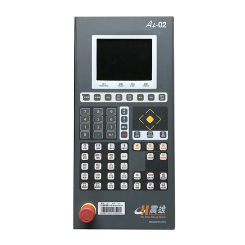
1.1. Controller Panel Description:
04/08/13
1

CDC-2000 操作手冊 Operational Manual
1.2. Manually Operational Keys:
1) In manual mode, Operational keys can accomplish a particular task of the whole
cycle. The process of the operational cycle is shown below:
Clamp Inj.Carri.F
Injec.
Inj.Carri.B
Plastic
Screw Dec.
Eject. Fw
M.Op.
Eject.Bw
04/08/13
2

CDC-2000 操作手冊 Operational Manual
The functions of the manually operational keys are shown below:
:Mode open.
: Mode close.
: Ejector backward.
: Ejector forward.
: In manual mode, when pulling core is set on Menu (06),this button
can move the core 1 backward manually.
: In manual mode, when pulling core is set on Menu (06), this button
can move the core 1 forward manually.
: 1. In manual mode, when mould screw is set on Menu (07), this button
can move the screw forward manually.
2. In manual mode, when mould thickness is set on Menu (09), this
button can adjust the platen backward manually.
3. In manual mode, when pulling core is set on Menu (06), this button
can move the core 2 forward manually.
: 1. In manual mode, when mould screw is set on Menu (07), this button
can move the screw backward manually.
2. In manual mode, when mould thickness is set on Menu (09), this
button can adjust the platen forward manually.
3. In manual mode, when pulling core is set on Menu (06), this button
can move the core 2 backward manually.
: Auto adjustment of mold thickness (Not used now).
04/08/13
3

CDC-2000 操作手冊 Operational Manual
: Safety door open (Not used now).
: Safety door close (Not used now).
: Injection carriage forward.
: Injection carriage backward.
: Injection.
: Plasticizing.
: Screw decompression.
1.3. Number Operational Keys:
04/08/13
4

CDC-2000 操作手冊 Operational Manual
Operational functions are shown below:
: Number “0” or blank space.
: Number “1” or alphabets “S”,”T”,”U”.
: Number “2” or alphabets “V”,”W”,”X”.
: Number “3” or alphabets “Y”,”Z”,”_”.
: Number “4” or alphabets “J”,”K”,”L”.
: Number “5” or alphabets “M”,”N”,”O”.
: Number “6” or alphabets “P”,”Q”,”R”.
: Number “7” or alphabets “A”,”B”,”C”.
: Number “8” or alphabets “D”,”E”,”F”.
: Number “9” or alphabets “G”,”H”,”I”.
: Cursor upward.
: Cursor downward.
: Cursor to left.
: Cursor to right.
The parametric setting value can be changed if the bottom is yellow.
: Function selection, “open” or “close” or increased by “+1”.
04/08/13
5

CDC-2000 操作手冊 Operational Manual
: Function selection, “open” or “close” or decreased by “-1”.
: 1.Auto calculation.
2.This button is used to call the Memorial Display when no cursor appears.
: Confirmation of right digit input.
: Cancellation of wrong digit input.
: Reconfirmation of data input.
1.4. Combined Operational Keys :
+ : Memorize the current Menu.
+ : When the pressure and speed curves are on screen, press this
button to display standard display curve. Referred to Menu (48)
of 2.15.
+ : Back up 1.
+ : Back up 2.
+ : Back up 3.
+ : Back up 4.
+ : Print the current Menu, don’t use it when no printer. Otherwise,
The CDC-2000 will stop to work.
1.5. Power Operational Keys:
1) To Push the E-stop to turn off the power of the Controller; to rotate the
04/08/13
6

CDC-2000 操作手冊 Operational Manual
E-stop and the button will arise, then to push key can turn on the
power of the controller.
1.6. Motor Operational Keys:
: Start motor, LED Light located on the upper left of the button is on if the
upper left would be off. The motor can’t be stopped under automatic mode.
: Stop motor, push this button to stop the motor, and LED light on the upper
left would be off. The motor can’t be stopped under automatic mode.
1.7. The Function of Operational Keys on screen:
MANUAL OPERATION MODE 4 / 5 11:25
MOLD NO. NOZZLE T1 T2 T3 T4 T5 T6 Tc
YYYYYYYY AA% BBB CCC DDD EEE FFF GGG HHH
aaaaaaaaaaa
Sbb Pcc Bdd bbb ccc ddd eee fff ggg hhh
EEEE.Emm
BATCH NO. : WWWWW
GOOD PART NO. : XXXXX
OOOO.Omm PPPP.Pmm QQQQ.Qmm SSSkg/cm2 RRRrpm
SET M
畫面 01
F1 F2 F3 F4 F5 F6 F7 F8 F9 F10
04/08/13
7

CDC-2000 操作手冊 Operational Manual
1.7.1. After the start-up system Menu test is finished, Menu switches to Operational Menu (01),
The two bottom lines which have the yellow background are the Menu names that are
often used. Press the fast-selection keys can switch to the required Menu. For example,
if you press on Menu (01) as shown above, Menu switches to Mold close and
Mold open setting Menu. The Operational functions of the keys are shown below:
: Power on button for controller.
: Quick menu switchover, used to switch to menu shown at the screen bottom.
: Quick menu switchover, used to switch to menu shown at the screen bottom.
: Quick menu switchover, used to switch to menu shown at the screen bottom.
: Quick menu switchover, used to switch to menu shown at the screen bottom.
: Quick menu switchover, used to switch to menu shown at the screen bottom.
: Quick menu switchover, used to switch to menu shown at the screen bottom.
: Quick menu switchover, used to switch to menu shown at the screen bottom.
: Quick menu switchover, used to switch to menu shown at the screen bottom.
: Quick menu switchover, used to switch to menu shown at the screen bottom.
: Quick menu switchover, used to switch to menu shown at the screen bottom.
: 1. Switch to operational Menu.
2. When on the operational Menu, This button is used to switch the menu
shown at the bottom of the screen.
04/08/13
8

CDC-2000 操作手冊 Operational Manual
1.7.2. CDC-2000 Menu and index tables are shown below for reference:
1)
Menu Mold close
Mold open Ejector injection plasticizing
screw Temperature
setting products
counter functional
selection Time
Settin
g
Prompt
setting Cycle
Monitor
Index
03 04 11 14 20 43 32 35 19 62
Menu Mold no
setting Carriage Temperature
Timer Core pull unscrew Air-blew Modulating
mold Input
monitor Output
monitor Peripheral
Setting
Index
42 15 23 06 07 08 09 40 41 46
Menu Mold close
Mole open split
nuts ejector Core pull unscrew Air-blow Modulating
Mold lubrication
Index
03 05 04 06 07 08 09 10
2)
Menu Mold close
Mold open ejector injection Plasticizing
screw Temperature
setting Products
counter Functional
selection Time
setting Prompt
setting Cycle
monitor
Index
03 04 11 14 20 43 32 35 19 62
Screen
Display
Mold no
setting carriage Temperature
timer Core pull Unscrew Air- blew Modulating
Mold Input
monitor Output
monitor Peripheral
setting
Index 42 15 23 06 07 08 09 40 41 46
Menu injection
Plasticizing
Screw carriage Pressure
Velocity
curve
Injection
volume Prompt
setting Cycle
monitor
Index 11 14 15 48 16 19
Menu Injection
volume Injection
Rate Injection
Pressure Plasticizing
screw
Index 16 17 18 14
04/08/13
9

CDC-2000 操作手冊 Operational Manual
3)
Menu Mold close
Mold open ejector Injection Plasticizing
screw Temperature
setting Products
counter Functional
Selection Time
setting Prompt
setting Cycle
monitor
Index 03 04 11 14 20 43 32 35 19 62
Menu Mold no
setting Carriage Temperature
Timer Core pull unscrew Air-blew modulating Input
monitor Output
monitor Peripheral
setting
Index 42 15 23 06 07 08 09 40 41 46
Screen
Display Temperature
Setting Setting
curve Temperature
timer Heating
curve
Index 20 21 23 24
Screen
Display Temperature
setting T1 T2 T3 T4 T5 T6 TC 校正
Index 20 24 25 26 27 28 29 30 50
4)
Screen
Display Mold close
Mold open ejector Injection Plasticizing
screw Temperature
setting Products
counter Functional
selection Time
setting Prompt
setting Cycle
monitor
Index 03 04 11 14 20 43 32 35 19 62
Menu Mold no
setting Carriage Temperature
timer Core pull
unscrew Air-blew Modulating
mold Input
monitor Output
monitor Peripheral
Setting
Index 42 15 23 06 07 08 09 40 41 46
Screen
Display Mold no
setting products
counter Quality
record SPC
chart Quality
curve
Index 42 43 44 13 61
04/08/13
10

CDC-2000 操作手冊 Operational Manual
5)
Screen
Display Mold no
setting carriage Temperature
timer Core pull unscrew Air-blew Modulating
mold Input
monitor Output
monitor peripheral
setting
Index 42 15 23 06 07 08 09 40 41 46
Screen
Display Program
monitor Relay
monitor Counter
monitor 時間制
檢視
Input
monitor Output
monitor
Index 36 37 38 39 40 41
6)
Screen
Display Mold close
Mold Open Ejector injection Plasticizing
screw Temperature
setting Products
counter Functional
selection Time
setting Prompt
setting Cycle
monitor
Index 03 04 11 14 20 43 32 35 19 62
Screen
Display Function
selection Pressure
Velocity
setting
Counter
setting Time unit
setting
Index 32 33 34 35
7)
Screen
Display Mold no
setting carriage Temperature
timer Core pull unscrew Air-blew Modulating
mold Input
monitor Output
monitor Periphery
setting
Index 42 15 23 06 07 08 09 40 41 46
Screen
Display Product
information Parameter
variation Breakdown
record Peripheral
setting 機器
資訊
Index 45 31 49 46 51 57 47
initial
restore
1.8. The function of keys in forming operational status:
: Manual mode selection key, the LED indicator on upper left of the button is on
when the controller is in manual mode.
: Semi-auto mode selection key, the LED indicator on upper left of the button is
on when the controller is in semi-auto mode.
04/08/13
11

CDC-2000 操作手冊 Operational Manual
: Auto mode selection key, the LED indicator on upper left of the button is on when
the controller is in auto mode.
If the LED indicators on or or are twinkling, all of the data can not
to changed. Please refer to section 2.45 “interface and password setting”.
04/08/13
12

CDC-2000 操作手冊 Operational Manual
2. Computer Menu:
2.1. System Starting Menu
震雄機械廠股份有限公司
CHEN HSONG MACHINERY TAIWAN CO.,LTD.
Factory address: Sung Chiang N. Road. Chung Li Industrial District Chung Li,
Taoyuan, R. O. C.
TEL : 886-3-452-2288
FAX : 886-3-452-0261
Machine type : SM-3100 Machine no. : 1234567
The data of production: 2000/01 The present date : 2000/01/31 Func
tional : A3000000 Program version: AF00
Chart 00
F1 F2 F3 F4 F5 F6 F7 F8 F9 F10
Testing, please waiting
To check the safe e
q
ui
p
ments before lestarin
g
When the power is on, the system shows the Menu (00) and do the functional testing, and
automatically change to Menu (01) about 3 seconds later. The functional testing Menu (00) shows
the related data of the machine to the customer for reference:
A) Factory address: Sung Chiang N.Road, Chung Li Industrial District Chung Li,
Taoyuan, Taiwan, R.O.C.
B) TEL: Factory’s telephone no. “886-3-452-2288”.
C) FAX: Factory’s fax no. “886-3-452-0261”.
E) Machine type :The machinery type “SM-3100”.
F) Machine no.: The machinery no. “1234567”.
G) The date of production: What date was the machine produced? “2000/01”。
H) The present date: What date is today? “2000/01/31”。
I) Functional no.: to record the machinery functional no. “A3000000”。
J) Program version :indicated the software version “AF00”。
04/08/13
13

CDC-2000 操作手冊 Operational Manual
2.2. Manual Operation Setting
Manual monitor chart 01/31 11:25
Mold no. nozzle T1 T2 T3 T4 T5 T6 Tc
YYYYYYYY AA% BBB CCC DDD EEE FFF GGG HHH
aaaaaaa
Sbb Pcc Bdd bbb ccc ddd eee fff ggg hhh
EEEE.Emm
Total products : WWWWW
Good products : XXXXX
OOOO.Omm PPPP.Pmm QQQQ.Qmm SSSkg/cm2 RRRrpm
Mold c ejector inject. plast. Temp. produ. funct. Time prompt cycle
Mold o screw settin
g
count. Selec. Settin
g
settin
g
monitor
Chart 01A
F1 F2 F3 F4 F5 F6 F7 F8 F9 F10
Press button to show manual operational setting Menu(01),the LED indicator
on the upper left is on. When the power is on, the system is in manual mode and
doesn’t need to use this button. In manual mode, if the Menu is not like this one,
press or to go to Menu (01).
Move the cursor to the parameter that you want to change, adjust the parameter
by numerical keys, then push key to finish the correction. The setting
descriptions of “mould open & close” Menu (01) are shown below:
A) “YYYYYYYY”: Display the contents of mold no.
B) “AA”: Proportional nozzle heating setting.
C) “BBB”: Temperature setting of barrel sector 1.
D) “bbb” :The practical temperature of barrel sector 1.
E) “CCC”: Temperature setting of barrel sector 2.
F) “ccc” :The practical temperature of barrel sector 2.
G) “DDD”: Temperature setting of barrel sector 3.
H) “ddd” :The practical temperature of barrel sector 3.
I) “EEE”: Temperature setting of barrel sector 4.
04/08/13
14

CDC-2000 操作手冊 Operational Manual
J) “eee” :The practical temperature of barrel sector 4.
K) “FFF”: Temperature setting of barrel sector 5.
L) “fff” :The practical temperature of barrel sector 5.
M) “GGG”: Temperature setting of barrel sector 6.
N) “ggg” :The practical temperature of barrel sector 6.
O) “HHH”: The backup temperature setting.
P) “hhh” : The practical backup temperature display.
Q) “WWWWW”: Display the volume of product.
R) “XXXXX”: Display the volume of good product.
S) “OOOO.O”: Display the present location of ejector.
T) “PPPP.P”: Display the present location of clamping.
U) “QQQQ.Q”: Display the present location of ejection.
V) “RRR”: Display the speed of screw rotation in plasticizing.
W) “SSS”: Display the present hydraulic pressure.
2.3. Auto Operation Setting
Auto display chart 01/31 11:25
Mold no. nozzle T1 T2 T3 T4 T5 T6 Tc
YYYYYYYY AA% BBB CCC DDD EEE FFF GGG HHH
aaaaaaa
Sbb Pcc Bdd bbb ccc ddd eee fff ggg hhh
EEEE.Emm
Total products : WWWWW injection time : KKKK.K
Good products : XXXXX cooling time : LLLL.L
Cycle time : MMMM.M middle time : NNNN.N
OOOO.Omm PPPP.Pmm QQQQ.Qmm SSSkg/cm2 RRRrpm
Mold c ejector inject. plast. Temp. product funct. Time prompt cycle
Mold o screw settin
g
count. Selec. Settin
g
settin
g
monitor
Chart 02A
F1 F2 F3 F4 F5 F6 F7 F8 F9 F10
04/08/13
15

CDC-2000 操作手冊 Operational Manual
Auto monitor chart 01/31 11:25
Mold no. nozzle T1 T2 T3 T4 T5 T6 Tc
YYYYYYYY AA% BBB CCC DDD EEE FFF GGG HHH
aaaaaaa
Sbb Pcc Bdd bbb ccc ddd eee fff ggg hhh
EEEE.Emm
Total products : WWWWW injection time : KKKK.K
Good products : XXXXX cooling time : LLLL.L
Cycle time : MMMM.M middle time : NNNN.N
OOOO.Omm PPPP.Pmm QQQQ.Qmm SSSkg/cm2 RRRrpm
Mold c ejector inject. Plast. tempe.Product funct. Time prompt cycle
Mold o screw settin
g
count. Select.settin
g
settin
g
monitor
Chart 02B
F1 F2 F3 F4 F5 F6 F7 F8 F9 F10
Push or to show Menu (02), the LED indicator on the upper left is on.
In auto operation mode, if the Menu is not like this one, press or
or to go to Menu (02).
Move the cursor to the parameter that you want to change, adjust the parameter
by numerical keys, the push key to finish the correction. The setting
descriptions of “Auto Monitor “ Menu (02) are shown below:
A) “YYYYYYYY” :Display the contents of mold no.
B) “AA” : Proportional nozzle heating setting.
C) “BBB” :Temperature setting of barrel sector 1.
D) “bbb” :The practical temperature of barrel sector 1.
E) “CCC” :Temperature setting of barrel sector 2.
F) “ccc” :The practical temperature of barrel sector 2.
G) “DDD” :Temperature setting of barrel sector 3.
H) “ddd” :The practical temperature of barrel sector 3.
I) “EEE” :Temperature setting of barrel sector 4.
J) “eee” :The practical temperature of barrel sector 4.
04/08/13
16
Table of contents
Other Chen Hsong Desktop manuals
