Chentronics SureSpark LO-2 User manual

RELATED DOCUMENT –MUST COMPLY WITH SCHEDULE DOCUMENT(S):
CDM-139, CDM-140, CDM-206, CDM-111, CDM-112, CDM-114, CDM-180
FOR A LIST OF RELEVANT PATENTS
AND TRADEMARKS PLEASE SEE
CHENTRONICS.COM/LEGAL-NOTICES
SURESPARK LO MANUAL
PAGE 1 OF 28
ISO 9001 CERTIFIED
DRAWN BY:
AR
ON:
2022-MAR-04
LAST REV BY:
xyz
ON:
x/y/z
DCO No. 14804
DWG. No. MNL-SURESPARK LO
REV. F
THIS DRAWING OWNED BY CHENTRONICS. IT IS
CONDITIONALLY LOANED AND IS TO BE RETURNED UPON
REQUEST. THE BORROWER BY RECEIVING IT HAS AGREED
NOT TO REPRODUCE NOR COPY IT IN WHOLE OR IN PART
NOR TO FURNISH INFORMATION FROM IT TO OTHERS NOR
TO MAKE ANY USE OF IT THAT IS OR MAY BE INJURIOUS TO
CHENTRONICS. FOR MORE INFORMATION PLEASE CONTACT
CHENTRONICS AT +1.607.334.5531.
TOLERANCE NOTES
FABRICATED TOLERANCES
≥2 ft (610 mm) ± 0.250 in (6.4 mm)
< 2ft (610 mm) ± 0.125 in (3.2 mm)
MACHINED TOLERANCES
± 0.050 DECIMAL DIM (1 PLACE)
± 0.010 DECIMAL DIM (2 PLACES)
± 0.005 DECIMAL DIM (3 PLACES)
SURESPARK LO MANUAL
LO-2, LO-4, Dual LO-4, & LO-6 High Energy Ignition Systems
Installation and Operation Manual
PN: 07070204-xxx PN: 07070214-xxx PN: 07670204-xxx
PN: 07070404-xxx PN: 07070414-xxx PN: 07670404-xxx
PN: 07070604-xxx PN: 07070614-xxx PN: 07670604-xxx
PN: 07072404-GXI
KEEP THIS MANUAL IN A SAFE PLACE
FOR FUTURE REFERENCE
READ THIS MANUAL BEFORE USING THIS PRODUCT.FAILURE TO FOLLOW THE INSTRUCTIONS AND SAFETY
PRECAUTIONS IN THIS MANUAL CAN RESULT IN SEVERE INJURY,DEATH,OR DAMAGE TO EQUIPMENT.
FOR A LIST OF RELEVANT PATENTS AND TRADEMARKS, PLEASE SEE CHENTRONICS.COM/LEGAL-NOTICES
RELATED DOCUMENT –MUST COMPLY WITH SCHEDULE DOCUMENT(S):
CDM-139, CDM-140, CDM-206, CDM-111, CDM-112, CDM-114, CDM-180
FOR A LIST OF RELEVANT PATENTS
AND TRADEMARKS PLEASE SEE
CHENTRONICS.COM/LEGAL-NOTICES
SURESPARK LO MANUAL
PAGE 2 OF 28
ISO 9001 CERTIFIED
DRAWN BY:
AR
ON:
2022-MAR-04
LAST REV BY:
xyz
ON:
x/y/z
DCO No. 14804
DWG. No. MNL-SURESPARK LO
REV. F
THIS DRAWING OWNED BY CHENTRONICS. IT IS
CONDITIONALLY LOANED AND IS TO BE RETURNED UPON
REQUEST. THE BORROWER BY RECEIVING IT HAS AGREED
NOT TO REPRODUCE NOR COPY IT IN WHOLE OR IN PART
NOR TO FURNISH INFORMATION FROM IT TO OTHERS NOR
TO MAKE ANY USE OF IT THAT IS OR MAY BE INJURIOUS TO
CHENTRONICS. FOR MORE INFORMATION PLEASE CONTACT
CHENTRONICS AT +1.607.334.5531.
TOLERANCE NOTES
FABRICATED TOLERANCES
≥2 ft (610 mm) ± 0.250 in (6.4 mm)
< 2ft (610 mm) ± 0.125 in (3.2 mm)
MACHINED TOLERANCES
± 0.050 DECIMAL DIM (1 PLACE)
± 0.010 DECIMAL DIM (2 PLACES)
± 0.005 DECIMAL DIM (3 PLACES)
SURESPARK LO MANUAL
Contents
1.0 Important Safety Information........................................................................................................ 3
2.0 Definition ...................................................................................................................................... 5
3.0 System Specifications .................................................................................................................... 5
3.1 Description of Equipment ................................................................................................................................. 5
3.2 General Arrangements...................................................................................................................................... 6
3.3 Enclosure Configurations: ................................................................................................................................. 9
3.4 Description of Equipment ............................................................................................................................... 10
3.5 Equipment Conditions of Use ......................................................................................................................... 10
3.6 System Electrical and Physical Specifications.................................................................................................. 11
4.0 Installation Instructions............................................................................................................... 14
4.1 Instructions for Lifting..................................................................................................................................... 14
4.2 Mounting ........................................................................................................................................................ 14
4.3 2-Wire Harness and Base Rod Installation ...................................................................................................... 15
4.4 ½in NPT Male Harness and Base Rod Installation........................................................................................... 15
4.5 02 Series Igniter and Extension Rod Installation............................................................................................. 16
4.6 Coaxial Output Harness and Igniter Installation ............................................................................................. 17
4.7 Safety wire Installation (Optional) .................................................................................................................. 18
4.8 Wiring Installation........................................................................................................................................... 19
4.9 Installing the Igniter into a Burner.................................................................................................................. 21
4.10 Equipment Earth Bond.................................................................................................................................... 21
5.0 System Operational Inputs and Outputs...................................................................................... 23
5.1 Terminal Key ................................................................................................................................................... 23
5.2 Electrical Area Classification and Safety Markings.......................................................................................... 24
5.3 System Schematic Diagram............................................................................................................................. 25
5.4 Firing the Igniter.............................................................................................................................................. 26
5.5 Spark Indicator................................................................................................................................................ 26
5.6 Igniter Wear Detection ................................................................................................................................... 26
6.0 Maintenance ............................................................................................................................... 27
6.1 Service............................................................................................................................................................. 27
6.2 Cleaning .......................................................................................................................................................... 27
7.0 Standard Components and Accessories ....................................................................................... 28
7.1 Standard 2-Wire Output System Components................................................................................................ 28
7.2 Standard ARP 670 Coaxial System Components ............................................................................................. 28
7.3 Standard Explosion Proof Enclosure System Components ............................................................................. 28
8.0 Warranty Instructions.................................................................................................................. 28
9.0 Technical Support........................................................................................................................ 28

RELATED DOCUMENT –MUST COMPLY WITH SCHEDULE DOCUMENT(S):
CDM-139, CDM-140, CDM-206, CDM-111, CDM-112, CDM-114, CDM-180
FOR A LIST OF RELEVANT PATENTS
AND TRADEMARKS PLEASE SEE
CHENTRONICS.COM/LEGAL-NOTICES
SURESPARK LO MANUAL
PAGE 3 OF 28
ISO 9001 CERTIFIED
DRAWN BY:
AR
ON:
2022-MAR-04
LAST REV BY:
xyz
ON:
x/y/z
DCO No. 14804
DWG. No. MNL-SURESPARK LO
REV. F
THIS DRAWING OWNED BY CHENTRONICS. IT IS
CONDITIONALLY LOANED AND IS TO BE RETURNED UPON
REQUEST. THE BORROWER BY RECEIVING IT HAS AGREED
NOT TO REPRODUCE NOR COPY IT IN WHOLE OR IN PART
NOR TO FURNISH INFORMATION FROM IT TO OTHERS NOR
TO MAKE ANY USE OF IT THAT IS OR MAY BE INJURIOUS TO
CHENTRONICS. FOR MORE INFORMATION PLEASE CONTACT
CHENTRONICS AT +1.607.334.5531.
TOLERANCE NOTES
FABRICATED TOLERANCES
≥2 ft (610 mm) ± 0.250 in (6.4 mm)
< 2ft (610 mm) ± 0.125 in (3.2 mm)
MACHINED TOLERANCES
± 0.050 DECIMAL DIM (1 PLACE)
± 0.010 DECIMAL DIM (2 PLACES)
± 0.005 DECIMAL DIM (3 PLACES)
SURESPARK LO MANUAL
1.0 Important Safety Information
Read All Instructions Before Using the Equipment
The instructions in this manual serve as a general guide. It is intended for use by qualified personnel
with knowledge of equipment of this type. It is not intended to cover all possible variations in
equipment or to provide for specific operating problems which may arise.
You are responsible for adhering to all warnings or cautions provided in this manual.
In addition to any general safety measures provided in this manual, you must comply with all national,
state, local, and company safety regulations.
Safety Symbols used in this manual comply with ISO 3864.
THESE SYMBOLS INDICATE POTENTIAL PERSONAL INJURY HAZARDS.
OBEY ALL SAFETY MESSAGES THAT FOLLOW THESE SYMBOLS TO AVOID POSSIBLE INJURY OR DEATH.
Indicates a hazard with a high level of risk, which, if not avoided,
will result in death or severe injury.
Indicates a hazard with a medium level of risk, which, if not
avoided, could result in death or severe injury.
Indicates a hazard with a low level of risk, which, if not avoided,
will result in minor or moderate injury.

RELATED DOCUMENT –MUST COMPLY WITH SCHEDULE DOCUMENT(S):
CDM-139, CDM-140, CDM-206, CDM-111, CDM-112, CDM-114, CDM-180
FOR A LIST OF RELEVANT PATENTS
AND TRADEMARKS PLEASE SEE
CHENTRONICS.COM/LEGAL-NOTICES
SURESPARK LO MANUAL
PAGE 4 OF 28
ISO 9001 CERTIFIED
DRAWN BY:
AR
ON:
2022-MAR-04
LAST REV BY:
xyz
ON:
x/y/z
DCO No. 14804
DWG. No. MNL-SURESPARK LO
REV. F
THIS DRAWING OWNED BY CHENTRONICS. IT IS
CONDITIONALLY LOANED AND IS TO BE RETURNED UPON
REQUEST. THE BORROWER BY RECEIVING IT HAS AGREED
NOT TO REPRODUCE NOR COPY IT IN WHOLE OR IN PART
NOR TO FURNISH INFORMATION FROM IT TO OTHERS NOR
TO MAKE ANY USE OF IT THAT IS OR MAY BE INJURIOUS TO
CHENTRONICS. FOR MORE INFORMATION PLEASE CONTACT
CHENTRONICS AT +1.607.334.5531.
TOLERANCE NOTES
FABRICATED TOLERANCES
≥2 ft (610 mm) ± 0.250 in (6.4 mm)
< 2ft (610 mm) ± 0.125 in (3.2 mm)
MACHINED TOLERANCES
± 0.050 DECIMAL DIM (1 PLACE)
± 0.010 DECIMAL DIM (2 PLACES)
± 0.005 DECIMAL DIM (3 PLACES)
SURESPARK LO MANUAL
HAZARDOUS VOLTAGE
The equipment contains a High Energy Ignition System, which contains DANGEROUS AND POTENTIALLY
LETHAL VOLTAGE. To avoid the risk of serious injury from electric shock, always follow the safety
precautions listed below:
Disconnect power before servicing the equipment.
Ensure the equipment is appropriately bonded to earth before use. See Section 4.10 regarding
equipment earth bond locations.
Do not join or separate any connection to the equipment when the equipment is energized.
Do not apply power to the equipment without an igniter.
Keep the igniter firing end away from all personnel and flammable material.
The equipment must be installed and serviced by qualified personnel per this manual and applicable
local and national codes, standards, and ordinances.
The equipment is not field-repairable. Do not attempt to disassemble or repair the equipment.
Les symboles de sécurité utilisés dans ce manuel sont conformes à la norme ISO
3864.
CES SYMBOLES SONT UTILISÉS POUR VOUS AVERTIR DES RISQUES DE BLESSURES POTENTIELS.
RESPECTEZ TOUS LES MESSAGES DE SÉCURITÉ QUI SUIVENT CES SYMBOLES POUR ÉVITER LES BLESSURES POTENTIELLES OU
LA MORT.
Indique un danger avec un niveau élevé de risque qui, s’il n'est pas
évité, entraînera la mort ou des blessures graves.
Indique un danger avec un niveau de risque moyen qui, s’il n'est pas
évité, pourrait entraîner la mort ou des blessures graves.
Indique un danger avec un niveau de risque bas qui, s’il n'est pas
évité, entraînera des blessures mineures ou modérées.
RELATED DOCUMENT –MUST COMPLY WITH SCHEDULE DOCUMENT(S):
CDM-139, CDM-140, CDM-206, CDM-111, CDM-112, CDM-114, CDM-180
FOR A LIST OF RELEVANT PATENTS
AND TRADEMARKS PLEASE SEE
CHENTRONICS.COM/LEGAL-NOTICES
SURESPARK LO MANUAL
PAGE 5 OF 28
ISO 9001 CERTIFIED
DRAWN BY:
AR
ON:
2022-MAR-04
LAST REV BY:
xyz
ON:
x/y/z
DCO No. 14804
DWG. No. MNL-SURESPARK LO
REV. F
THIS DRAWING OWNED BY CHENTRONICS. IT IS
CONDITIONALLY LOANED AND IS TO BE RETURNED UPON
REQUEST. THE BORROWER BY RECEIVING IT HAS AGREED
NOT TO REPRODUCE NOR COPY IT IN WHOLE OR IN PART
NOR TO FURNISH INFORMATION FROM IT TO OTHERS NOR
TO MAKE ANY USE OF IT THAT IS OR MAY BE INJURIOUS TO
CHENTRONICS. FOR MORE INFORMATION PLEASE CONTACT
CHENTRONICS AT +1.607.334.5531.
TOLERANCE NOTES
FABRICATED TOLERANCES
≥2 ft (610 mm) ± 0.250 in (6.4 mm)
< 2ft (610 mm) ± 0.125 in (3.2 mm)
MACHINED TOLERANCES
± 0.050 DECIMAL DIM (1 PLACE)
± 0.010 DECIMAL DIM (2 PLACES)
± 0.005 DECIMAL DIM (3 PLACES)
SURESPARK LO MANUAL
TENSION DANGEREUSE
L'appareil contient un système d'allumage à haute énergie qui contient une TENSION DANGEREUSE ET
POTENTIELLEMENT MORTELLE. Pour éviter les risques de blessures graves par électrocution, suivez
toujours les précautions de sécurité indiquées ci-dessous:
Coupez l'alimentation avant l'entretien du matériel.
S'assurer que l'équipement est correctement mis à la terre avant l'utilisation. Voir la section 4.10
concernant l'emplacement des liaisons à la terre de l’équipement.
Ne pas connecter ou séparer toute connexion à l'équipement lorsque l'appareil est sous tension.
Ne pas appliquer de tension à l'appareil sans un allumeur.
Gardez l’extrémité de l'allumeur loin de tout personnel et de matériels inflammables.
L'équipement doit être installé et entretenu par du personnel qualifié, conformément à ce manuel, aux
codes locaux et nationaux applicables, et aux normes et règlements en vigueur.
L'appareil n'est pas réparable sur site. Ne tentez pas de démonter ou de réparer l'équipement.
2.0 Definition
Spark:An electric current arc.
High Energy Ignition: Electric spark ignition system utilizing high energy sparks for direct ignition of
hydrocarbon fuels such as gas, diesel, or #6 oil.
High Energy Exciter: An electronic device that stores electric charge and releases it cyclically in abrupt
bursts to an igniter to create high-power sparks.
3.0 System Specifications
3.1 Description of Equipment
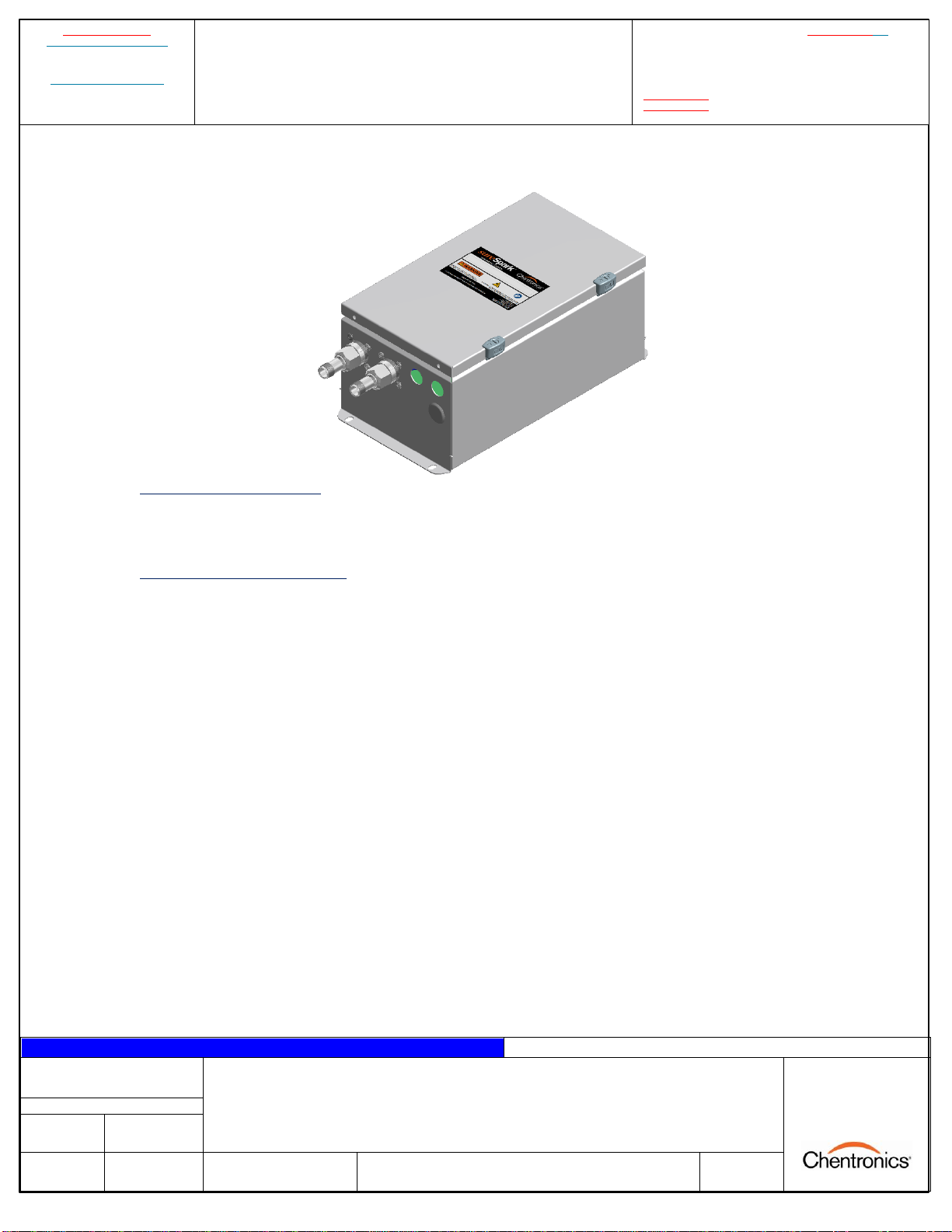
The Chentronics® SureSpark™High Energy Exciter LO-2, LO-4, and LO-6 series high energy ignition
systems are specifically designed to ignite gas, light oil (#2), and diesel fuels directly while operating in a
wide range of environmental conditions. For convenience, there is an external Spark LED (two for dual
units, one per output) which indicates when the igniter is sparking and when the igniter tip needs to be
replaced. This allows the user to replace igniter tips before they fail and prevent ignition faults from
occurring. The Igniter Wear indicator also turns red when an igniter fault is detected and remains on
until the run signal is cycled. This additional feature allows for easier location of failed units when
multiple units are being operated simultaneously.

RELATED DOCUMENT –MUST COMPLY WITH SCHEDULE DOCUMENT(S):
CDM-139, CDM-140, CDM-206, CDM-111, CDM-112, CDM-114, CDM-180
FOR A LIST OF RELEVANT PATENTS
AND TRADEMARKS PLEASE SEE
CHENTRONICS.COM/LEGAL-NOTICES
SURESPARK LO MANUAL
PAGE 6 OF 28
ISO 9001 CERTIFIED
DRAWN BY:
AR
ON:
2022-MAR-04
LAST REV BY:
xyz
ON:
x/y/z
DCO No. 14804
DWG. No. MNL-SURESPARK LO
REV. F
THIS DRAWING OWNED BY CHENTRONICS. IT IS
CONDITIONALLY LOANED AND IS TO BE RETURNED UPON
REQUEST. THE BORROWER BY RECEIVING IT HAS AGREED
NOT TO REPRODUCE NOR COPY IT IN WHOLE OR IN PART
NOR TO FURNISH INFORMATION FROM IT TO OTHERS NOR
TO MAKE ANY USE OF IT THAT IS OR MAY BE INJURIOUS TO
CHENTRONICS. FOR MORE INFORMATION PLEASE CONTACT
CHENTRONICS AT +1.607.334.5531.
TOLERANCE NOTES
FABRICATED TOLERANCES
≥2 ft (610 mm) ± 0.250 in (6.4 mm)
< 2ft (610 mm) ± 0.125 in (3.2 mm)
MACHINED TOLERANCES
± 0.050 DECIMAL DIM (1 PLACE)
± 0.010 DECIMAL DIM (2 PLACES)
± 0.005 DECIMAL DIM (3 PLACES)
SURESPARK LO MANUAL
3.2 General Arrangements
Coaxial Output LO Series Exciter
Figure 2: Ordinary area, Coaxial LO series ignition system general arrangement.
NOTE: Harness and igniter are sold separately.
2-Wire LO Series Exciter
Figure 3: Ordinary area, 2-Wire LO series ignition system general arrangement.
NOTE: Harness, base rod, extension rod (optional), and igniter are sold separately.

RELATED DOCUMENT –MUST COMPLY WITH SCHEDULE DOCUMENT(S):
CDM-139, CDM-140, CDM-206, CDM-111, CDM-112, CDM-114, CDM-180
FOR A LIST OF RELEVANT PATENTS
AND TRADEMARKS PLEASE SEE
CHENTRONICS.COM/LEGAL-NOTICES
SURESPARK LO MANUAL
PAGE 7 OF 28
ISO 9001 CERTIFIED
DRAWN BY:
AR
ON:
2022-MAR-04
LAST REV BY:
xyz
ON:
x/y/z
DCO No. 14804
DWG. No. MNL-SURESPARK LO
REV. F
THIS DRAWING OWNED BY CHENTRONICS. IT IS
CONDITIONALLY LOANED AND IS TO BE RETURNED UPON
REQUEST. THE BORROWER BY RECEIVING IT HAS AGREED
NOT TO REPRODUCE NOR COPY IT IN WHOLE OR IN PART
NOR TO FURNISH INFORMATION FROM IT TO OTHERS NOR
TO MAKE ANY USE OF IT THAT IS OR MAY BE INJURIOUS TO
CHENTRONICS. FOR MORE INFORMATION PLEASE CONTACT
CHENTRONICS AT +1.607.334.5531.
TOLERANCE NOTES
FABRICATED TOLERANCES
≥2 ft (610 mm) ± 0.250 in (6.4 mm)
< 2ft (610 mm) ± 0.125 in (3.2 mm)
MACHINED TOLERANCES
± 0.050 DECIMAL DIM (1 PLACE)
± 0.010 DECIMAL DIM (2 PLACES)
± 0.005 DECIMAL DIM (3 PLACES)
SURESPARK LO MANUAL
LO Series Exciter with Explosion Proof Enclosure
Figure 4: LO series ignition system with explosion-proof enclosure general arrangement.
NOTE: Harness, base rod, extension rod (optional), and igniter are sold separately.
Coaxial Dual Output LO-4 Exciter
Figure 5: SureSpark™High Energy Exciter Coaxial Dual Output ignition system general arrangement (ARP 670 Type 5F
connections).
NOTE: Harnesses and igniters are sold separately.

RELATED DOCUMENT –MUST COMPLY WITH SCHEDULE DOCUMENT(S):
CDM-139, CDM-140, CDM-206, CDM-111, CDM-112, CDM-114, CDM-180
FOR A LIST OF RELEVANT PATENTS
AND TRADEMARKS PLEASE SEE
CHENTRONICS.COM/LEGAL-NOTICES
SURESPARK LO MANUAL
PAGE 8 OF 28
ISO 9001 CERTIFIED
DRAWN BY:
AR
ON:
2022-MAR-04
LAST REV BY:
xyz
ON:
x/y/z
DCO No. 14804
DWG. No. MNL-SURESPARK LO
REV. F
THIS DRAWING OWNED BY CHENTRONICS. IT IS
CONDITIONALLY LOANED AND IS TO BE RETURNED UPON
REQUEST. THE BORROWER BY RECEIVING IT HAS AGREED
NOT TO REPRODUCE NOR COPY IT IN WHOLE OR IN PART
NOR TO FURNISH INFORMATION FROM IT TO OTHERS NOR
TO MAKE ANY USE OF IT THAT IS OR MAY BE INJURIOUS TO
CHENTRONICS. FOR MORE INFORMATION PLEASE CONTACT
CHENTRONICS AT +1.607.334.5531.
TOLERANCE NOTES
FABRICATED TOLERANCES
≥2 ft (610 mm) ± 0.250 in (6.4 mm)
< 2ft (610 mm) ± 0.125 in (3.2 mm)
MACHINED TOLERANCES
± 0.050 DECIMAL DIM (1 PLACE)
± 0.010 DECIMAL DIM (2 PLACES)
± 0.005 DECIMAL DIM (3 PLACES)
SURESPARK LO MANUAL
2-Wire Dual Output LO-4 Exciter
Figure 6: SureSpark™High Energy Exciter 2-Wire Dual Output ignition system general arrangement.
NOTE: Harnesses, base rods, extension rods (optional), and igniters are sold separately.
Coaxial Dual Output LOTS system
Figure 7: SureSpark™High Energy Exciter LOTS system general arrangement.
NOTE: Harnesses and igniters are sold separately.

RELATED DOCUMENT –MUST COMPLY WITH SCHEDULE DOCUMENT(S):
CDM-139, CDM-140, CDM-206, CDM-111, CDM-112, CDM-114, CDM-180
FOR A LIST OF RELEVANT PATENTS
AND TRADEMARKS PLEASE SEE
CHENTRONICS.COM/LEGAL-NOTICES
SURESPARK LO MANUAL
PAGE 9 OF 28
ISO 9001 CERTIFIED
DRAWN BY:
AR
ON:
2022-MAR-04
LAST REV BY:
xyz
ON:
x/y/z
DCO No. 14804
DWG. No. MNL-SURESPARK LO
REV. F
THIS DRAWING OWNED BY CHENTRONICS. IT IS
CONDITIONALLY LOANED AND IS TO BE RETURNED UPON
REQUEST. THE BORROWER BY RECEIVING IT HAS AGREED
NOT TO REPRODUCE NOR COPY IT IN WHOLE OR IN PART
NOR TO FURNISH INFORMATION FROM IT TO OTHERS NOR
TO MAKE ANY USE OF IT THAT IS OR MAY BE INJURIOUS TO
CHENTRONICS. FOR MORE INFORMATION PLEASE CONTACT
CHENTRONICS AT +1.607.334.5531.
TOLERANCE NOTES
FABRICATED TOLERANCES
≥2 ft (610 mm) ± 0.250 in (6.4 mm)
< 2ft (610 mm) ± 0.125 in (3.2 mm)
MACHINED TOLERANCES
± 0.050 DECIMAL DIM (1 PLACE)
± 0.010 DECIMAL DIM (2 PLACES)
± 0.005 DECIMAL DIM (3 PLACES)
SURESPARK LO MANUAL
3.3 Enclosure Configurations:
The SureSpark™High Energy Exciter LO-2, LO-4, and LO-6 systems are available in the enclosure
configurations as described below:
•07070x04-xxx –Plate-metal enclosure with painted mild steel, 304 stainless steel, or 316
stainless steel options. Available with optional spark switch.
•07070x14-xxx –Fiberglass enclosure with optional spark switch.
•07670x04-xxx –Explosion-proof enclosure with optional spark switch.
RELATED DOCUMENT –MUST COMPLY WITH SCHEDULE DOCUMENT(S):
CDM-139, CDM-140, CDM-206, CDM-111, CDM-112, CDM-114, CDM-180
FOR A LIST OF RELEVANT PATENTS
AND TRADEMARKS PLEASE SEE
CHENTRONICS.COM/LEGAL-NOTICES
SURESPARK LO MANUAL
PAGE 10 OF 28
ISO 9001 CERTIFIED
DRAWN BY:
AR
ON:
2022-MAR-04
LAST REV BY:
xyz
ON:
x/y/z
DCO No. 14804
DWG. No. MNL-SURESPARK LO
REV. F
THIS DRAWING OWNED BY CHENTRONICS. IT IS
CONDITIONALLY LOANED AND IS TO BE RETURNED UPON
REQUEST. THE BORROWER BY RECEIVING IT HAS AGREED
NOT TO REPRODUCE NOR COPY IT IN WHOLE OR IN PART
NOR TO FURNISH INFORMATION FROM IT TO OTHERS NOR
TO MAKE ANY USE OF IT THAT IS OR MAY BE INJURIOUS TO
CHENTRONICS. FOR MORE INFORMATION PLEASE CONTACT
CHENTRONICS AT +1.607.334.5531.
TOLERANCE NOTES
FABRICATED TOLERANCES
≥2 ft (610 mm) ± 0.250 in (6.4 mm)
< 2ft (610 mm) ± 0.125 in (3.2 mm)
MACHINED TOLERANCES
± 0.050 DECIMAL DIM (1 PLACE)
± 0.010 DECIMAL DIM (2 PLACES)
± 0.005 DECIMAL DIM (3 PLACES)
SURESPARK LO MANUAL
•07072404-xxx –Dual-Output, Plate-metal enclosure with painted mild steel, 304 stainless
steel, or 316 stainless steel options. Available with optional spark switch.
3.4 Description of Equipment
The equipment is sealed in an enclosure that has an IP66 rating. The 304/316 stainless steel or fiberglass
enclosure options provide NEMA Type 4X rating.
3.5 Equipment Conditions of Use
The SureSpark™High Energy Exciter system equipment is subject to the following conditions of use and
limitations:
1. All wiring must be rated at or above 90°C. The installation must use a conduit or an
entry hub to protect the wiring from damage.
2. A switch or circuit breaker to separate the device from the mains must be included in
the installation. The switch or circuit breaker must be suitably located and easily
reached. It is recommended that it be located near the exciter enclosure.
3. The lid shall not be unlocked or opened until the power has been turned off for at least
5 minutes.
4. The equipment shall not be subjected to ambient temperatures greater than +75°C or
less than -25°C while operating. For the LO-2 series, +60°C shall not be exceeded.
5. The equipment's igniter connections shall not be joined or separated when the
equipment is in use (powered).
6. The equipment shall not be operated without an igniter attached.
7. Equipment shall be adequately grounded. Please see Section 4.10 regarding earth bond
requirements in this manual.
8. The igniter, extension rod, or base rod must be secured to the grounded building frame
using a metal fixture.
RELATED DOCUMENT –MUST COMPLY WITH SCHEDULE DOCUMENT(S):
CDM-139, CDM-140, CDM-206, CDM-111, CDM-112, CDM-114, CDM-180
FOR A LIST OF RELEVANT PATENTS
AND TRADEMARKS PLEASE SEE
CHENTRONICS.COM/LEGAL-NOTICES
SURESPARK LO MANUAL
PAGE 11 OF 28
ISO 9001 CERTIFIED
DRAWN BY:
AR
ON:
2022-MAR-04
LAST REV BY:
xyz
ON:
x/y/z
DCO No. 14804
DWG. No. MNL-SURESPARK LO
REV. F
THIS DRAWING OWNED BY CHENTRONICS. IT IS
CONDITIONALLY LOANED AND IS TO BE RETURNED UPON
REQUEST. THE BORROWER BY RECEIVING IT HAS AGREED
NOT TO REPRODUCE NOR COPY IT IN WHOLE OR IN PART
NOR TO FURNISH INFORMATION FROM IT TO OTHERS NOR
TO MAKE ANY USE OF IT THAT IS OR MAY BE INJURIOUS TO
CHENTRONICS. FOR MORE INFORMATION PLEASE CONTACT
CHENTRONICS AT +1.607.334.5531.
TOLERANCE NOTES
FABRICATED TOLERANCES
≥2 ft (610 mm) ± 0.250 in (6.4 mm)
< 2ft (610 mm) ± 0.125 in (3.2 mm)
MACHINED TOLERANCES
± 0.050 DECIMAL DIM (1 PLACE)
± 0.010 DECIMAL DIM (2 PLACES)
± 0.005 DECIMAL DIM (3 PLACES)
SURESPARK LO MANUAL
3.6 System Electrical and Physical Specifications
LO-2 Specifications:
Application: High-energy, direct-spark ignition system
Input Power: 100-240VAC 50/60Hz, 0.5A MAX
Exciter Type: High Energy Ignition
Exciter Duty Cycle: 100% Continuous
Exciter Spark Command: With the jumper, apply power to begin sparking.
Without the jumper, apply 24V DC, close contacts, or push-
button switch (optional) to begin sparking.
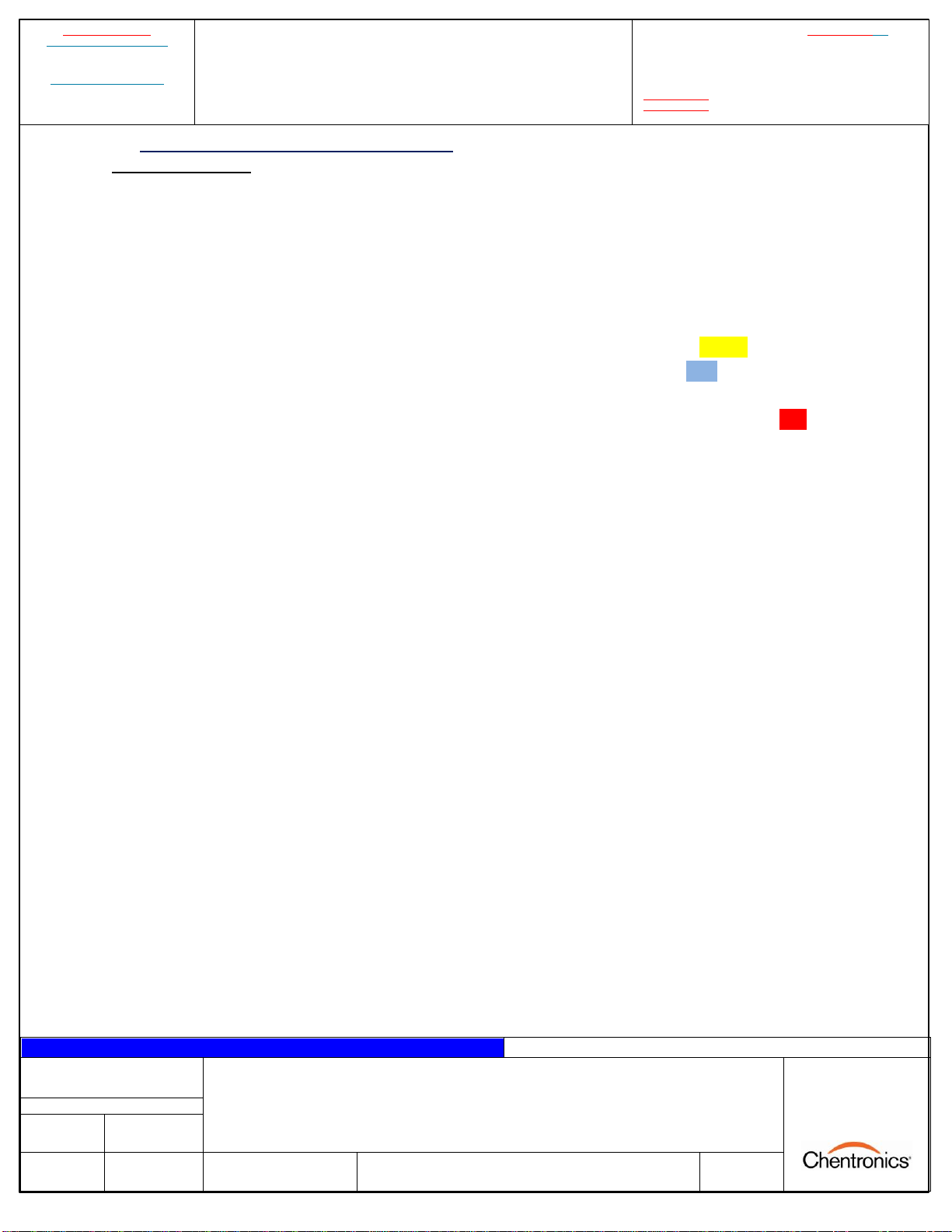
Exciter Spark Indicator: When powered and on standby, LED is solid Yellow.
When attempting to spark, LED turns Blue and flashes off
steadily when successful spark output currents are detected.
Igniter Wear Indicator: When an igniter fault is detected, LED turns on solid Red and
remains on until the spark signal is removed and re-applied.
Exciter Energy: 12J min per Spark
Exciter Spark Rate: 2 SPS min
Operating Temperature Limits: -25°C to 60°C
Storage Temperature Limits: -40°C to 105°C
Humidity: 0 to 100% condensing
Enclosure:
07070204: Brushed Stainless Steel (304 or 316)
or Gray Painted Mild Steel
07070214: Fiberglass
07670204: Copper Free Cast Aluminum
Weight:
07070204: Approximately 15lb (7 kg)
07070214: Approximately 11lb (5 kg)
07670204: Approximately 35lb (16 kg)
Dimensions:
07070204: 8.4 x 6.6 x 10 in
07070214: 7.6 x 6.2 x 9.6 in
07670204: 11.6 x 8.0 x 10.5 in
RELATED DOCUMENT –MUST COMPLY WITH SCHEDULE DOCUMENT(S):
CDM-139, CDM-140, CDM-206, CDM-111, CDM-112, CDM-114, CDM-180
FOR A LIST OF RELEVANT PATENTS
AND TRADEMARKS PLEASE SEE
CHENTRONICS.COM/LEGAL-NOTICES
SURESPARK LO MANUAL
PAGE 12 OF 28
ISO 9001 CERTIFIED
DRAWN BY:
AR
ON:
2022-MAR-04
LAST REV BY:
xyz
ON:
x/y/z
DCO No. 14804
DWG. No. MNL-SURESPARK LO
REV. F
THIS DRAWING OWNED BY CHENTRONICS. IT IS
CONDITIONALLY LOANED AND IS TO BE RETURNED UPON
REQUEST. THE BORROWER BY RECEIVING IT HAS AGREED
NOT TO REPRODUCE NOR COPY IT IN WHOLE OR IN PART
NOR TO FURNISH INFORMATION FROM IT TO OTHERS NOR
TO MAKE ANY USE OF IT THAT IS OR MAY BE INJURIOUS TO
CHENTRONICS. FOR MORE INFORMATION PLEASE CONTACT
CHENTRONICS AT +1.607.334.5531.
TOLERANCE NOTES
FABRICATED TOLERANCES
≥2 ft (610 mm) ± 0.250 in (6.4 mm)
< 2ft (610 mm) ± 0.125 in (3.2 mm)
MACHINED TOLERANCES
± 0.050 DECIMAL DIM (1 PLACE)
± 0.010 DECIMAL DIM (2 PLACES)
± 0.005 DECIMAL DIM (3 PLACES)
SURESPARK LO MANUAL
LO-4 Specifications:
Application: High-energy, direct-spark ignition system
Input Power: 100-240VAC 50/60Hz, 1A MAX
Exciter Type: High Energy Ignition
Exciter Duty Cycle: 5 min on, 10 min off
Exciter Spark Command: With the jumper, apply power to begin sparking.
Without jumper, apply 24V DC, close contacts, or push-button
switch (optional) to spark.
Exciter Spark Indicator: When powered and on standby, LED is solid Yellow.
When attempting to spark, LED turns Blue and flashes off
steadily when successful spark output currents are detected.
Igniter Wear Indicator: When an igniter fault is detected, LED turns on solid Red and
remains on until the spark signal is removed and re-applied.
Exciter Energy: 12J min per Spark
Exciter Spark Rate: 4 SPS min
Operating Temperature Limits: -25°C to 75°C
Storage Temperature Limits: -40°C to 105°C
Humidity: 0 to 100% condensing
Enclosure:
07070404: Brushed Stainless Steel (304 or 316)
or Gray Painted Mild Steel
07070414: Fiberglass
07670404: Copper Free Cast Aluminum
Weight:
07070404: Approximately 15lb (7 kg)
07070414: Approximately 11lb (5 kg)
07670404: Approximately 35lb (16 kg)
Dimensions:
07070404: 8.4 x 6.6 x 10 in
07070414: 7.6 x 6.2 x 9.6 in
07670404: 11.6 x 8.0 x 10.5 in

RELATED DOCUMENT –MUST COMPLY WITH SCHEDULE DOCUMENT(S):
CDM-139, CDM-140, CDM-206, CDM-111, CDM-112, CDM-114, CDM-180
FOR A LIST OF RELEVANT PATENTS
AND TRADEMARKS PLEASE SEE
CHENTRONICS.COM/LEGAL-NOTICES
SURESPARK LO MANUAL
PAGE 13 OF 28
ISO 9001 CERTIFIED
DRAWN BY:
AR
ON:
2022-MAR-04
LAST REV BY:
xyz
ON:
x/y/z
DCO No. 14804
DWG. No. MNL-SURESPARK LO
REV. F
THIS DRAWING OWNED BY CHENTRONICS. IT IS
CONDITIONALLY LOANED AND IS TO BE RETURNED UPON
REQUEST. THE BORROWER BY RECEIVING IT HAS AGREED
NOT TO REPRODUCE NOR COPY IT IN WHOLE OR IN PART
NOR TO FURNISH INFORMATION FROM IT TO OTHERS NOR
TO MAKE ANY USE OF IT THAT IS OR MAY BE INJURIOUS TO
CHENTRONICS. FOR MORE INFORMATION PLEASE CONTACT
CHENTRONICS AT +1.607.334.5531.
TOLERANCE NOTES
FABRICATED TOLERANCES
≥2 ft (610 mm) ± 0.250 in (6.4 mm)
< 2ft (610 mm) ± 0.125 in (3.2 mm)
MACHINED TOLERANCES
± 0.050 DECIMAL DIM (1 PLACE)
± 0.010 DECIMAL DIM (2 PLACES)
± 0.005 DECIMAL DIM (3 PLACES)
SURESPARK LO MANUAL
LO-6 Specifications:
Application: High-energy, direct-spark ignition system
Input Power: 100-240VAC 50/60Hz, 1.5A MAX
Exciter Type: High Energy Ignition
Exciter Duty Cycle: 5 min on, 10 min off
Exciter Spark Command: With the jumper, apply power to begin sparking.
Without jumper, apply 24V DC, close contacts, or push-button
switch (optional) to spark.
Exciter Spark Indicator: When powered and on standby, LED is solid Yellow.
When attempting to spark, LED turns Blue and flashes off
steadily when successful spark output currents are detected.
Igniter Wear Indicator: When an igniter fault is detected, LED turns on solid Red and
remains on until the spark signal is removed and re-applied.
Exciter Energy: 12J min per Spark
Exciter Spark Rate: 6 SPS min
Operating Temperature Limits: -25°C to 75°C
Storage Temperature Limits: -40°C to 105°C
Humidity: 0 to 100% condensing
Enclosure:
07070604: Brushed Stainless Steel (304 or 316)
or Gray Painted Mild Steel
07070614: Fiberglass
07670604: Copper Free Cast Aluminum
Weight:
07070604: Approximately 15lb (7 kg)
07070614: Approximately 11lb (5 kg)
07670604: Approximately 35lb (16 kg)
Dimensions:
07070604: 8.4 x 6.6 x 10 in
07070614: 7.6 x 6.2 x 9.6 in
07670604: 11.6 x 8.0 x 10.5 in

RELATED DOCUMENT –MUST COMPLY WITH SCHEDULE DOCUMENT(S):
CDM-139, CDM-140, CDM-206, CDM-111, CDM-112, CDM-114, CDM-180
FOR A LIST OF RELEVANT PATENTS
AND TRADEMARKS PLEASE SEE
CHENTRONICS.COM/LEGAL-NOTICES
SURESPARK LO MANUAL
PAGE 14 OF 28
ISO 9001 CERTIFIED
DRAWN BY:
AR
ON:
2022-MAR-04
LAST REV BY:
xyz
ON:
x/y/z
DCO No. 14804
DWG. No. MNL-SURESPARK LO
REV. F
THIS DRAWING OWNED BY CHENTRONICS. IT IS
CONDITIONALLY LOANED AND IS TO BE RETURNED UPON
REQUEST. THE BORROWER BY RECEIVING IT HAS AGREED
NOT TO REPRODUCE NOR COPY IT IN WHOLE OR IN PART
NOR TO FURNISH INFORMATION FROM IT TO OTHERS NOR
TO MAKE ANY USE OF IT THAT IS OR MAY BE INJURIOUS TO
CHENTRONICS. FOR MORE INFORMATION PLEASE CONTACT
CHENTRONICS AT +1.607.334.5531.
TOLERANCE NOTES
FABRICATED TOLERANCES
≥2 ft (610 mm) ± 0.250 in (6.4 mm)
< 2ft (610 mm) ± 0.125 in (3.2 mm)
MACHINED TOLERANCES
± 0.050 DECIMAL DIM (1 PLACE)
± 0.010 DECIMAL DIM (2 PLACES)
± 0.005 DECIMAL DIM (3 PLACES)
SURESPARK LO MANUAL
Dual Output LO-4 Specifications:
Application: High-energy, direct-spark ignition system
Input Power: 100-240VAC 50/60Hz, 2A MAX
Exciter Type: High Energy Ignition
Exciter Duty Cycle: 5 min on, 10 min off
Exciter Spark Command: With the jumper, apply power to begin sparking.
Without jumper, apply 24V DC, close contacts, or push-button
switch (optional) to spark.
Exciter Spark Indicator: When powered and on standby, LED is solid Yellow.
When attempting to spark, LED turns Blue and flashes off
steadily when successful spark output currents are detected.
Igniter Wear Indicator: When an igniter fault is detected, LED turns on solid Red and
remains on until the spark signal is removed and re-applied.
Exciter Energy: 2x 12J min per Spark
Exciter Spark Rate: 2x 4 SPS min
Operating Temperature Limits: -25°C to 75°C
Storage Temperature Limits: -40°C to 105°C
Humidity: 0 to 100% condensing
Enclosure: Brushed Stainless Steel (304 or 316)
or Gray Painted Mild Steel
Weight: Approximately 30lb (14 kg)
Dimensions: 10.0 x 7.0 x 17.3 in
4.0 Installation Instructions
4.1 Instructions for Lifting
The exciter should be carried only by someone capable of safely lifting 35lb.
4.2 Mounting
For mounting dimensions, refer to the equipment data sheet. The exciter should be mounted to a firm
structure. The exciter output is characterized as a high current transient pulse. Typical discharge
currents are exponential decay with peaks of approximately 1000 amps that last less than 1ms. Although
the coaxial construction and outer shielding suppress much of the electromagnetic field, separating
ignition cables from signal cables is good practice to prevent noise coupling. However, the ignition
circuit is unaffected by other (nearby) ignition sources, and multiple output cables can share the same
tray.

RELATED DOCUMENT –MUST COMPLY WITH SCHEDULE DOCUMENT(S):
CDM-139, CDM-140, CDM-206, CDM-111, CDM-112, CDM-114, CDM-180
FOR A LIST OF RELEVANT PATENTS
AND TRADEMARKS PLEASE SEE
CHENTRONICS.COM/LEGAL-NOTICES
SURESPARK LO MANUAL
PAGE 15 OF 28
ISO 9001 CERTIFIED
DRAWN BY:
AR
ON:
2022-MAR-04
LAST REV BY:
xyz
ON:
x/y/z
DCO No. 14804
DWG. No. MNL-SURESPARK LO
REV. F
THIS DRAWING OWNED BY CHENTRONICS. IT IS
CONDITIONALLY LOANED AND IS TO BE RETURNED UPON
REQUEST. THE BORROWER BY RECEIVING IT HAS AGREED
NOT TO REPRODUCE NOR COPY IT IN WHOLE OR IN PART
NOR TO FURNISH INFORMATION FROM IT TO OTHERS NOR
TO MAKE ANY USE OF IT THAT IS OR MAY BE INJURIOUS TO
CHENTRONICS. FOR MORE INFORMATION PLEASE CONTACT
CHENTRONICS AT +1.607.334.5531.
TOLERANCE NOTES
FABRICATED TOLERANCES
≥2 ft (610 mm) ± 0.250 in (6.4 mm)
< 2ft (610 mm) ± 0.125 in (3.2 mm)
MACHINED TOLERANCES
± 0.050 DECIMAL DIM (1 PLACE)
± 0.010 DECIMAL DIM (2 PLACES)
± 0.005 DECIMAL DIM (3 PLACES)
SURESPARK LO MANUAL
4.3 2-Wire Harness and Base Rod Installation
Insert the male end of the harness into the connector on the exciter and fully hand-tighten it. Next,
connect the female end of the harness to the base rod and fully hand-tighten it.
Figure 8: Output Harness and Base Rod installation for units with 2-wire connectors.
4.4 ½in NPT Male Harness and Base Rod Installation
Install one end of the harness to the exciter enclosure by following the manufacturer's instructions for
cable-gland installation. Next, connect the black harness wire to the terminal marked "LO" and connect
the remaining harness wire (red or white) to the terminal marked "HI" on the exciter top board. A
correct connection is shown in Figure 9 below.
Figure 9: Correct connection of output harness wires with ½in NPT Male Harness.

RELATED DOCUMENT –MUST COMPLY WITH SCHEDULE DOCUMENT(S):
CDM-139, CDM-140, CDM-206, CDM-111, CDM-112, CDM-114, CDM-180
FOR A LIST OF RELEVANT PATENTS
AND TRADEMARKS PLEASE SEE
CHENTRONICS.COM/LEGAL-NOTICES
SURESPARK LO MANUAL
PAGE 16 OF 28
ISO 9001 CERTIFIED
DRAWN BY:
AR
ON:
2022-MAR-04
LAST REV BY:
xyz
ON:
x/y/z
DCO No. 14804
DWG. No. MNL-SURESPARK LO
REV. F
THIS DRAWING OWNED BY CHENTRONICS. IT IS
CONDITIONALLY LOANED AND IS TO BE RETURNED UPON
REQUEST. THE BORROWER BY RECEIVING IT HAS AGREED
NOT TO REPRODUCE NOR COPY IT IN WHOLE OR IN PART
NOR TO FURNISH INFORMATION FROM IT TO OTHERS NOR
TO MAKE ANY USE OF IT THAT IS OR MAY BE INJURIOUS TO
CHENTRONICS. FOR MORE INFORMATION PLEASE CONTACT
CHENTRONICS AT +1.607.334.5531.
TOLERANCE NOTES
FABRICATED TOLERANCES
≥2 ft (610 mm) ± 0.250 in (6.4 mm)
< 2ft (610 mm) ± 0.125 in (3.2 mm)
MACHINED TOLERANCES
± 0.050 DECIMAL DIM (1 PLACE)
± 0.010 DECIMAL DIM (2 PLACES)
± 0.005 DECIMAL DIM (3 PLACES)
SURESPARK LO MANUAL
Next, unscrew the cover on the base rod and install the other end of the harness to the base rod by
following the provided manufacturer instructions for cable-gland installation. Connect the black harness
wire to the green ground terminal (Figure 10) and tighten it. Next, connect the remaining harness wire
(red or white) to the rod wire using either the ceramic wire nut or the brass inline connector. For the
ceramic wire nut option, twist the wires together and terminate the connection by inserting the twisted
pair into the ceramic wire nut and tightening it by hand. For the brass inline connector option, pull back
the white sleeve on the base rod wire to reveal the brass inline connector, make the connection, and
pull the sleeve back to insulate the connector.
Figure 10: The case of the base rod.
NOTICE: Verify the rod wire is fully connected to the harness wire (RED or WHITE).
4.5 02 Series Igniter and Extension Rod Installation
To install the extension rod or igniter, press the male connector into the female connector and fully
hand-tighten it.
Figure 11: Series 02 igniter/extension rod connection.

RELATED DOCUMENT –MUST COMPLY WITH SCHEDULE DOCUMENT(S):
CDM-139, CDM-140, CDM-206, CDM-111, CDM-112, CDM-114, CDM-180
FOR A LIST OF RELEVANT PATENTS
AND TRADEMARKS PLEASE SEE
CHENTRONICS.COM/LEGAL-NOTICES
SURESPARK LO MANUAL
PAGE 17 OF 28
ISO 9001 CERTIFIED
DRAWN BY:
AR
ON:
2022-MAR-04
LAST REV BY:
xyz
ON:
x/y/z
DCO No. 14804
DWG. No. MNL-SURESPARK LO
REV. F
THIS DRAWING OWNED BY CHENTRONICS. IT IS
CONDITIONALLY LOANED AND IS TO BE RETURNED UPON
REQUEST. THE BORROWER BY RECEIVING IT HAS AGREED
NOT TO REPRODUCE NOR COPY IT IN WHOLE OR IN PART
NOR TO FURNISH INFORMATION FROM IT TO OTHERS NOR
TO MAKE ANY USE OF IT THAT IS OR MAY BE INJURIOUS TO
CHENTRONICS. FOR MORE INFORMATION PLEASE CONTACT
CHENTRONICS AT +1.607.334.5531.
TOLERANCE NOTES
FABRICATED TOLERANCES
≥2 ft (610 mm) ± 0.250 in (6.4 mm)
< 2ft (610 mm) ± 0.125 in (3.2 mm)
MACHINED TOLERANCES
± 0.050 DECIMAL DIM (1 PLACE)
± 0.010 DECIMAL DIM (2 PLACES)
± 0.005 DECIMAL DIM (3 PLACES)
SURESPARK LO MANUAL
4.6 Coaxial Output Harness and Igniter Installation
The exciter output is characterized as a high current transient pulse. It is good practice to separate
ignition cables from signal cables to prevent noise coupling. However, the ignition circuit is unaffected
by other (nearby) ignition sources, and multiple ignition cables can share the same tray.
Connect the harness to the output connector on the enclosure and wrench-tighten. Repeat this process
on the other end of the harness to connect the harness to the igniter. See Figure 12.
Figure 12: ARP 670 Coaxial Harness connections.

RELATED DOCUMENT –MUST COMPLY WITH SCHEDULE DOCUMENT(S):
CDM-139, CDM-140, CDM-206, CDM-111, CDM-112, CDM-114, CDM-180
FOR A LIST OF RELEVANT PATENTS
AND TRADEMARKS PLEASE SEE
CHENTRONICS.COM/LEGAL-NOTICES
SURESPARK LO MANUAL
PAGE 18 OF 28
ISO 9001 CERTIFIED
DRAWN BY:
AR
ON:
2022-MAR-04
LAST REV BY:
xyz
ON:
x/y/z
DCO No. 14804
DWG. No. MNL-SURESPARK LO
REV. F
THIS DRAWING OWNED BY CHENTRONICS. IT IS
CONDITIONALLY LOANED AND IS TO BE RETURNED UPON
REQUEST. THE BORROWER BY RECEIVING IT HAS AGREED
NOT TO REPRODUCE NOR COPY IT IN WHOLE OR IN PART
NOR TO FURNISH INFORMATION FROM IT TO OTHERS NOR
TO MAKE ANY USE OF IT THAT IS OR MAY BE INJURIOUS TO
CHENTRONICS. FOR MORE INFORMATION PLEASE CONTACT
CHENTRONICS AT +1.607.334.5531.
TOLERANCE NOTES
FABRICATED TOLERANCES
≥2 ft (610 mm) ± 0.250 in (6.4 mm)
< 2ft (610 mm) ± 0.125 in (3.2 mm)
MACHINED TOLERANCES
± 0.050 DECIMAL DIM (1 PLACE)
± 0.010 DECIMAL DIM (2 PLACES)
± 0.005 DECIMAL DIM (3 PLACES)
SURESPARK LO MANUAL
4.7 Safety wire Installation (Optional)
For applications in which electrical connections may be exposed to vibration, Chentronics® recommends
that the customer further secure ARP connections with safety wire. This is a common practice in
Aerospace as it helps prevent ARP connections from loosening during use. Please follow the installation
instructions as stated in Figure 13 and Figure 14
Figure 13: Safety Wire Installation –Output Harness to Igniter

RELATED DOCUMENT –MUST COMPLY WITH SCHEDULE DOCUMENT(S):
CDM-139, CDM-140, CDM-206, CDM-111, CDM-112, CDM-114, CDM-180
FOR A LIST OF RELEVANT PATENTS
AND TRADEMARKS PLEASE SEE
CHENTRONICS.COM/LEGAL-NOTICES
SURESPARK LO MANUAL
PAGE 19 OF 28
ISO 9001 CERTIFIED
DRAWN BY:
AR
ON:
2022-MAR-04
LAST REV BY:
xyz
ON:
x/y/z
DCO No. 14804
DWG. No. MNL-SURESPARK LO
REV. F
THIS DRAWING OWNED BY CHENTRONICS. IT IS
CONDITIONALLY LOANED AND IS TO BE RETURNED UPON
REQUEST. THE BORROWER BY RECEIVING IT HAS AGREED
NOT TO REPRODUCE NOR COPY IT IN WHOLE OR IN PART
NOR TO FURNISH INFORMATION FROM IT TO OTHERS NOR
TO MAKE ANY USE OF IT THAT IS OR MAY BE INJURIOUS TO
CHENTRONICS. FOR MORE INFORMATION PLEASE CONTACT
CHENTRONICS AT +1.607.334.5531.
TOLERANCE NOTES
FABRICATED TOLERANCES
≥2 ft (610 mm) ± 0.250 in (6.4 mm)
< 2ft (610 mm) ± 0.125 in (3.2 mm)
MACHINED TOLERANCES
± 0.050 DECIMAL DIM (1 PLACE)
± 0.010 DECIMAL DIM (2 PLACES)
± 0.005 DECIMAL DIM (3 PLACES)
SURESPARK LO MANUAL
Figure 14: Safety Wire Installation –Output Harness to Exciter
4.8 Wiring Installation
Single unit exciter wiring
The SureSpark™High Energy Exciter includes two enclosure entries for power/control. Wiring must be
rated at least 90°C. Connections should be made only when the equipment and wiring are not
energized. Once connected, the wiring should not be removed from the exciter until it has been de-
energized for at least 5 minutes.
The ignition circuit is unaffected by other (nearby) ignition sources, and multiple ignition cables can
share the same tray.
To power the exciters, apply 100-240VAC at 50/60 Hz between terminals L1 and L2 and connect the
terminals marked with the ground symbol to earth ground.
RELATED DOCUMENT –MUST COMPLY WITH SCHEDULE DOCUMENT(S):
CDM-139, CDM-140, CDM-206, CDM-111, CDM-112, CDM-114, CDM-180
FOR A LIST OF RELEVANT PATENTS
AND TRADEMARKS PLEASE SEE
CHENTRONICS.COM/LEGAL-NOTICES
SURESPARK LO MANUAL
PAGE 20 OF 28
ISO 9001 CERTIFIED
DRAWN BY:
AR
ON:
2022-MAR-04
LAST REV BY:
xyz
ON:
x/y/z
DCO No. 14804
DWG. No. MNL-SURESPARK LO
REV. F
THIS DRAWING OWNED BY CHENTRONICS. IT IS
CONDITIONALLY LOANED AND IS TO BE RETURNED UPON
REQUEST. THE BORROWER BY RECEIVING IT HAS AGREED
NOT TO REPRODUCE NOR COPY IT IN WHOLE OR IN PART
NOR TO FURNISH INFORMATION FROM IT TO OTHERS NOR
TO MAKE ANY USE OF IT THAT IS OR MAY BE INJURIOUS TO
CHENTRONICS. FOR MORE INFORMATION PLEASE CONTACT
CHENTRONICS AT +1.607.334.5531.
TOLERANCE NOTES
FABRICATED TOLERANCES
≥2 ft (610 mm) ± 0.250 in (6.4 mm)
< 2ft (610 mm) ± 0.125 in (3.2 mm)
MACHINED TOLERANCES
± 0.050 DECIMAL DIM (1 PLACE)
± 0.010 DECIMAL DIM (2 PLACES)
± 0.005 DECIMAL DIM (3 PLACES)
SURESPARK LO MANUAL
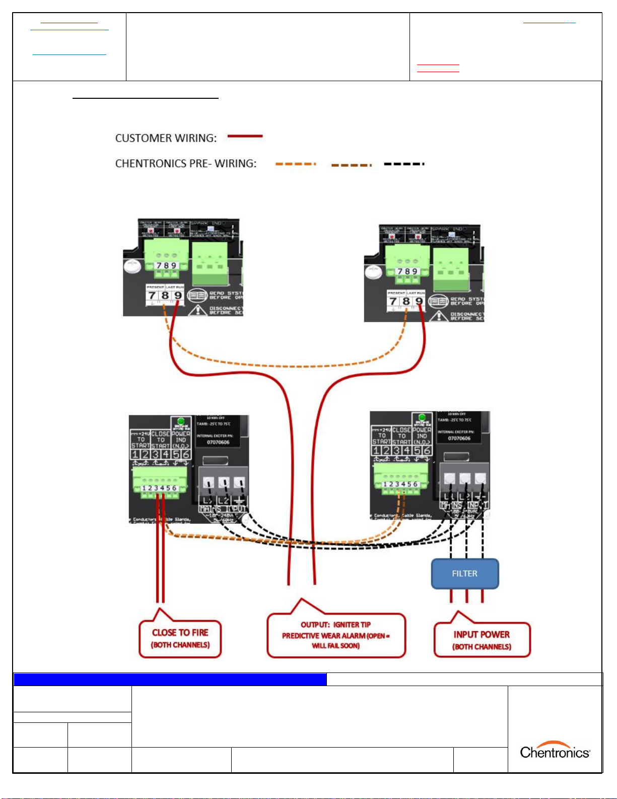
Dual unit exciter internal wiring
One set of contacts is used to fire both exciters, and wear indicator (fault) contacts for both exciters are
wired in series.
This manual suits for next models
3
Table of contents
Other Chentronics Industrial Equipment manuals


Popular Industrial Equipment manuals by other brands


Emerson
Emerson 581 Series RE-ASSEMBLY INSTRUCTIONS

Porvair Sciences
Porvair Sciences Ultravap Mistral User instruction manual

IRO
IRO 1131 X2 operating instructions

CMC
CMC Airmaster S1 Hardware installation guide

Milton Roy
Milton Roy YZ Systems NJEX 6300G-PM Instructions & operating manual

schmersal
schmersal PSC1 Series installation manual